/ohm/ - Electronics General: Hand-wound toroid edition
Thread suffered metal fatigue:
>>2939202
>I'm new to electronics. Where to get started?
It is an art/science of applying principles to requirements.
Find problem, learn principles, design and verify solution, build, test, post results, repeat.
Read the datasheet.
>OP source:
https://github.com/74HC14/ohmOP
bake at page 10, post in old thread
>Comprehensive list of electronics resources:
https://github.com/kitspace/awesome-electronics
>Project ideas:
https://hackaday.io
https://instructables.com/tag/type-id/category-technology/
https://adafruit.com
https://makezine.com/category/electronics/
>Books:
https://libgen.is/
>Principles (by increasing skill level):
Mims III, Getting Started in Electronics
Geier, How to Diagnose & Fix Everything Electronic
Kybett & Boysen, All New Electronics Self-Teaching Guide
Scherz & Monk, Practical Electronics for Inventors
Horowitz and Hill, The Art of Electronics
>Recommended software tools:
KiCAD 6+
Circuitmaker
Logisim Evolution
>Recommended Components/equipment:
Octopart
LCSC
eBay/AliExpress sellers, for component assortments/sample kits (caveat emptor)
Local independent electronics distributors
ladyada.net/library/procure/hobbyist.html
>Most relevant YouTube channels:
EEVblog
W2AEW
Moritz Klein
>microcontroller specific problems?
>>>/diy/mcg
>I have junk, what do?
Shitcan it
>consumer product support or PC building?
>>>/g/
>household/premises wiring?
More rules-driven than engineering, try /qtddtot/ or sparky general first
>antigravity and/or overunity?
Go away
Anonymous
10/18/2025, 12:10:32 PM
No.2951484
[Report]
Actual old thread:
>>2945584
Anonymous
10/18/2025, 2:12:42 PM
No.2951491
[Report]
>>2951482 (OP)
Once you start winding your own, its like a point of no return.
Anonymous
10/18/2025, 2:49:39 PM
No.2951494
[Report]
>>2951508
>>2951482 (OP)
https://electronicprojectsforfun.wordpress.com/rf-module-gallery/the-rf-splitter-and-combiner-gallery/a-resistive-tap-attenuator-for-rf-measurements/
why is this called a 40 db attenuator? isn't this just a resistor divider that reduces the input signal by 0.0199 (2460 ohms in series with 50 ohms) which is close to 20 db attenuation?
Calling out the phaseGODS in here
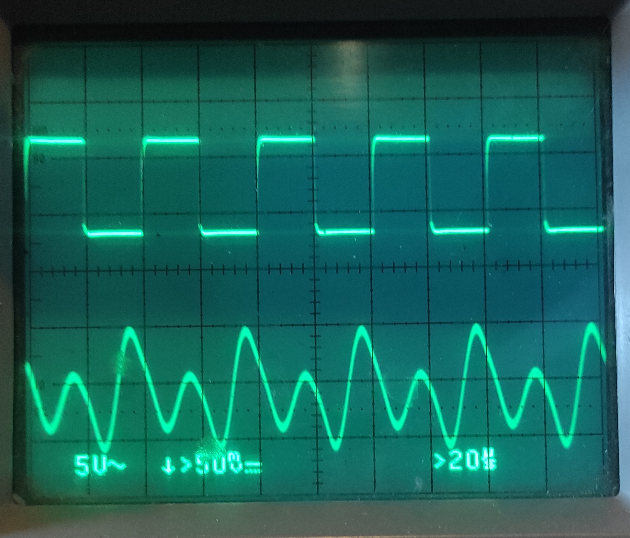
See pic. Top read is clock, bottom is same clock present in audio output. Need to substract such clock from signal, how the fuck do i turn that square into whatever wave is that in bottom so i can phase cancel it and effectively substract it from output?
Anonymous
10/18/2025, 3:34:16 PM
No.2951500
[Report]
>>2951514
>>2951499
1. Filter out harmonics
2. Feed into comparator
3. Profit idk
Anonymous
10/18/2025, 3:48:32 PM
No.2951503
[Report]
>>2951514
>>2951499
what youre looking at is the sum of a wave and its 2f harmonic. this should be concerning to you since square waves do not contain their 2f harmonics. its being generated elsewhere. my bet is an amplifier being thrown in and out of saturation somewhere. if you post a circuit it might make it more clear whats happening.
Anonymous
10/18/2025, 4:06:26 PM
No.2951508
[Report]
>>2951525
>>2951494
Values for attenuators are always given for power, not voltage.
Anonymous
10/18/2025, 4:19:51 PM
No.2951511
[Report]
>>2951512
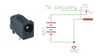
>have couple year old laptop with DC jack
>charger shits the bed one day
>Want to change it to usbc using a trigger board so it's not my only device with a bespoke charger anymore
>Cut off the jack from the charger, hook it to a bench psu and insert it
>Works
>Run 2 bodge wires (pins and body of jack are all on the ground plane aside from the positive) and test with bench psu
>Doesn't work
>After a few minutes of fiddle fucking plug the jack pigtail in with no power hooked to it
>Immediately starts accepting a charge (external power still hooked to bodge wires)
>The fuck
>Turns out the last little bit where it feels like the jack snaps in is what does it
Why would being hooked directly to the pins on the back of the jack which should bypass anything like that not work? I've confirmed that all parts of the jack other than the positive are all connected to the ground plane and do indeed show voltage when hooked up and measured, so I don't understand why some internal mechanism would still be able to interfere or what that mechanism might even be.
Anonymous
10/18/2025, 4:28:35 PM
No.2951512
[Report]
>>2951749
>>2951511
Maybe it's a switched jack.
>>2951500
The parasite signal is dynamic *meltingemoji*
>>2951503
Ty for the science. See pic, its a BBD delay, so, yes there will be audio distortion/filtering artifacts in the parasite wave. Thing is, the MN3007 from that circuit has two outputs and you pan them to filter out clock noise, however im not using that MN but one with a single output and the clock noise is loud. Im NOT lowpassing the output, i might at the very end but i need first to weaken the clock with phase tricks. Now have in mind that first scope is taken literally from the very audio output, so theres filtering from output pre, ill next post what it looks like taken right out the BBD
Anonymous
10/18/2025, 4:39:56 PM
No.2951515
[Report]
Anonymous
10/18/2025, 5:05:13 PM
No.2951521
[Report]
>>2951514
>MN3007
im not familiar with analog delay lines, but is the clock in question driving the sampling? if so, theres a much larger problem here: youre only able to capture frequencies at half your sampling rate. if your clock is 25 kHz like it is in the first scope pic, you should filter out anything above 12.5 kHz on the output, which will include the clock interference.
if you want to capture frequencies above 12.5 kHz, youll need to increase the clock frequency.
if that decreases the maximum delay to below what you require, youll need to daisy chain multiple BBDs.
and if youre still early in the design process, i would strongly consider using a microcontroller for this. pic rel goes for $6.50 on mouser.
Anonymous
10/18/2025, 5:48:44 PM
No.2951525
[Report]
>>2951508
thanks. it's so confusing keeping db vs dbm vs dbw etc. straight.
Anonymous
10/18/2025, 6:49:47 PM
No.2951531
[Report]
>>2951565
>>2951587
https://yageogroup.com/products/Capacitors/part/C2220C511KCGAC%7BBULK%7D
what do "current" and "voltage" mean here? as an example, at 10 MHz it shows 1.85A and 57.87V. is this some sort of a derating curve, and so at 10 MHz the absolute maximums are 1.85A and 57.87V? or is something completely different?
(i'm trying to understand how to select capacitors in a resonant circuit, so voltage and current limits are very important.)
Anonymous
10/18/2025, 8:56:15 PM
No.2951565
[Report]
>>2951531
if i had to guess, it seems like thats the experimental data they used for all the other data: voltage across cap vs current through cap. why they chose 176.78 V, i couldnt tell you. its also possible that the data is simulated, considering they have data for 176 V @ 10 GHz, which seems odd. but i definitely dont think its a derating curve.
Anonymous
10/18/2025, 9:37:30 PM
No.2951574
[Report]
>>2951514
Second BBD with an out-of-phase input clock, running in parallel? You could also use some FETs or an analogue switch IC to make an additional discrete BBD stage on the very end, allowing you to sum the two output signals like in the MN3007. Seems kinda useless to have a BBD IC without the two outputs, maybe an appnote will describe how to use it properly.
If the clock frequency will remain constant, tuning a multipole LPF will be a good idea, you won’t lose any signal information because of Nyquist’s sampling theorem.
If the clock frequency is variable, then maybe you can use some synchronous switched capacitor filter, likely with some integer factor between the BBD clock and the filter clock. I’ve never used switched capacitor filters though.
An edge-triggered sample+hold circuit may even work fine, only ever sample the output signal at the tiny rising edge of the clock (or better yet, of a clock 90 degrees out of phase via twisted ring-counter or PLL). That way you can ensure regardless of the clock’s contribution, you only ever sample it at the exact same place each time, and so turning the clock’s contribution into DC. It may attenuate your signal more than filtration, but you don’t have to worry about getting enough filter poles to fit between f and f/2.
Anonymous
10/18/2025, 10:02:03 PM
No.2951582
[Report]
>>2951499
>20µs grid
so that's a 25 kHz clock? and the signal below is way above that? just stick a low-pass filter on there. also you probably need a higher clock signal
Anonymous
10/18/2025, 10:14:39 PM
No.2951583
[Report]
>>2951586
>>2951589
From end of last thread I wrote:
Would hotswapping a DAC while power is still connected via the microcontroller (3.3v) be enough to kill its internal reference voltage? I think I did that...Vref is suddenly 0 and can't get it working again :(
someone asked "what DAC"...it's an AD5668.
Anonymous
10/18/2025, 10:25:33 PM
No.2951586
[Report]
>>2951611
>>2951583
what do you mean by hotswapping? desoldering it and soldering a new DAC in its place while power is on?
Anonymous
10/18/2025, 10:42:45 PM
No.2951587
[Report]
>>2951531
The current rating for capacitors is usually because of power dissipation limits. The current limit in the plots looks like it exactly follows the ESR.
Not really sure about the voltage,
https://www.wima.de/en/service/knowledge-base/special-technical-subjects/ says it's because of reduced dielectric strength of the ceramic at higher frequencies, but I definitely see the opposite trend in the paper-oil capacitors I usually work with.
Anonymous
10/18/2025, 10:47:50 PM
No.2951589
[Report]
>>2951583
I’m guessing it’s on one of those arduino breadboard modules? If it got voltage from one of its other pins for longer than Vcc then maybe. Especially the analogue inputs, as it may not have internal protection diodes on those.
Anonymous
10/19/2025, 12:03:13 AM
No.2951611
[Report]
>>2951638
>>2951586
I have it on a DIP adapter. I wanted to make room for something else, so I took it out of the breadboard (forgetting that the Arduino, which was feeding it 3.3v and SYNC, DIN, CLK, was still powered via USB) and when I put it back, the internal ref was 0. But I think it's not totally dead, just maybe the internal reference. I need to investigate more later
Anonymous
10/19/2025, 2:35:53 AM
No.2951638
[Report]
>>2951611
I see. well Anon, this is why we buy spares
Anonymous
10/19/2025, 6:25:06 PM
No.2951735
[Report]
any particular reason why a photodiode with a smaller capacitance would have a slower frequency response than one with a larger capacitance?
maybe smaller capacitance = wider junction, so the carriers just take longer to traverse it? i guess that makes sense, but i'd be curious to know what wavelength is the sweet spot for high-speed photo response, at least for current technology.
Anonymous
10/19/2025, 6:31:23 PM
No.2951737
[Report]
>>2951741
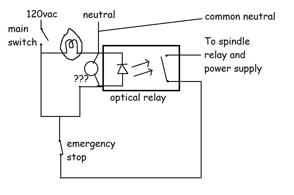
im pretty retarded with digital logic. Anyone willing to point me in the right direction for the following problem? Ideally i want to build this compact and without a microcontroller.
I have a Digital input, a Digital Output and a Stop Impuls.
When the Input is on, the Output is supposed to be on. When the Stop impuls triggers the Output is supposed to shut off, not turning back on again until the next rising edge on the Digital input
Anonymous
10/19/2025, 6:36:42 PM
No.2951741
[Report]
>>2951748
Anonymous
10/19/2025, 6:53:23 PM
No.2951748
[Report]
>>2951751
>>2951753
>>2951741
yea like that, but that leaves out the rising edge part. With In continuosly on and stop just being an impuls, the thing would turn off for just the duration of stop
Anonymous
10/19/2025, 6:53:27 PM
No.2951749
[Report]
>>2951512
Yeah, I was wrong and 1 of the pins isn't grounded, measuring between the pins I get 150k ohms and when I ground that pin then it starts accepting power, so I guess I'll just jump it to ground or if I really care and want to get fancy figure out how to hook it to the trigger board so it grounds when a cord is inserted
Anonymous
10/19/2025, 6:55:05 PM
No.2951751
[Report]
>>2951753
>>2951748
you can buy latches that are edge-triggered ("synchronous") on both inputs.
Anonymous
10/19/2025, 7:05:38 PM
No.2951753
[Report]
>>2951797
>>2951748
>>2951751
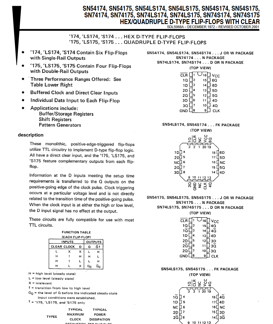
my apologies, apparently edge-triggered latches are called "flip-flops".
for pic rel, tie D high, tie CLOCK to the input, and tie CLEAR to stop. CLEAR is asynchronous but if stop is really just a pulse then it shouldnt matter.
also, if stop is some sort of analog signal, i would highly recommend using a comparator to convert it to standard logic voltages. also im just realizing CLEAR is active low so use the comparator to invert stop while youre at it.
Anonymous
10/19/2025, 9:11:08 PM
No.2951797
[Report]
>>2951753
thanks, thats exactly what im looking for.
>tie D high, tie CLOCK to the input
i never would have thought of that
>using a comparator
yea that was always the plan
Anonymous
10/19/2025, 10:49:33 PM
No.2951806
[Report]
>>2951808
>>2951812
Does anyone know what kind of component this is?
Anonymous
10/19/2025, 10:55:30 PM
No.2951808
[Report]
I listened to the anons advocating against stripboard so here I am learning KiCad for the first time
I'm not sure if I have the fortitude for this
Anonymous
10/19/2025, 11:11:51 PM
No.2951812
[Report]
>>2951822
>>2951806
Definitely a common-mode suppression choke. I saw a diagram that suggests the zig-zag means it’s a type-2 choke, whatever that means. Probably a different type of core material, or different shape.
>>2951809
I think there’s a way of autorouting on KiCAD with an addon, but I’ve never bothered. For a THT board I’d go into the settings for this file (one of the buttons at the top left) and change the default trace width to 0.5-1mm, instead of the tiny default.
If you select parts in the schematic viewer, they’ll be selected in the board layout too, so you can easily grab and move parts into sections before laying out. Then follow the rats nest.
Anonymous
10/19/2025, 11:45:04 PM
No.2951822
[Report]
>>2951825
>>2951812
does kicad have an autoplacer? would be neat if it did. minimize ratsnest overlap etc
Anonymous
10/19/2025, 11:59:54 PM
No.2951825
[Report]
>>2951822
It has both auto-placement and auto-routing. Whether or not those are useful is another matter. I don't use them, personally. In truth, I've never made any real effort to learn how to use the autorouter, and I'm too autismal about component placement to just let KiCad put them wherever it thinks is good.
I also don't do PCBs often enough to have grown out of finding drawing traces manually slightly cathartic, so...
Anonymous
10/20/2025, 12:18:34 AM
No.2951831
[Report]
>>2951833
>>2951809
the only thing more overwhelming than being faced with all of the lined up components at the start of routing is when you get about half way through and realise that you need to completely start over again but with the nagging doubt that your new layout idea won't work and you will need to reverse all the changes anyway.
good luck and have fun! if you want my advice just try and get as many nets untangled as possible before laying down any tracks at all
Anonymous
10/20/2025, 12:21:57 AM
No.2951833
[Report]
>>2951809
to add to what
>>2951831 is saying, I often start with ICs, the place related passives around them. once things looks reasonably untangled routing tends to be easy
Anonymous
10/20/2025, 12:48:11 AM
No.2951838
[Report]
>>2952490
>>2951809
I haven't messed with PCB design yet but all in all that doesn't seem so bad. You could knock it out in parts as well, in between gooning
Anonymous
10/20/2025, 1:09:43 AM
No.2951840
[Report]
>>2951871
>>2951915
>>2951809
Even if you end up making a pcb for it, usually you make one out of perfboard vector board or whatever first.
Anonymous
10/20/2025, 1:32:43 AM
No.2951843
[Report]
>>2951851
>>2951865
>>2951482 (OP)
need to pad my resume with projects and shit for internships
starting small, any suggestions for fun ones that are good to get my feet wet?
Anonymous
10/20/2025, 2:06:43 AM
No.2951851
[Report]
>>2951843
>any suggestions
toilet cam for scientific inquiry of real-world phenomenology
Anonymous
10/20/2025, 3:17:45 AM
No.2951865
[Report]
>>2951843
There’s some project lists in the OP repo. The “Don’t ask, roll” one has a mix of varying difficulties and utilities. I wrote this one instead because I’m autistic:
https://github.com/74HC14/ohmOP/blob/main/ProjectCategories.md
There’s also some utility projects that you should consider making if you don’t already own such a product, namely:
>CC/CV bench top PSU, lots of ways to approach this
>split-rail low-noise linear PSU for audio projects
>function generator, with lots of wave shapes
>amplifier for your function generator
There may be some other obvious ones I’m forgetting.
bored sound designer
10/20/2025, 3:30:22 AM
No.2951866
[Report]
>>2951873
I have a super cheap soldering iron, and I've realized maybe due to my skill issue, using it has led to many botched repair attempts.
I want to know about equipment for microsoldering specifically, which ones are nice or which ones you use or recommend. thanks
like fuck i can't even reliably repair a USB-C cable
Anonymous
10/20/2025, 3:49:17 AM
No.2951871
[Report]
>>2951915
>>2951840
not according to some anons in the last thread.
Anonymous
10/20/2025, 4:10:17 AM
No.2951873
[Report]
>>2951897
>>2951866
JBC C210 or C115 cartridges are meant to be good for tiny stuff, and there’s pretty good tip variety. JBC stations themselves are expensive, but the Chinese knockoff stations and USB irons are a plenty, knockoff tips are usually fine too. Importantly, there’s a lot of reviews for them out there, mainly on YouTube.
Seems so odd that there isn't better PCB software.
Anonymous
10/20/2025, 5:57:01 AM
No.2951892
[Report]
>>2951936
>>2951884
What more do you want? Personally I’d like it if KiCAD’s simulator wasn’t strictly tied to its schematic view, allowing you to have generic op-amps and power sources on the spice file alone. And for it to be easier to manage spice models, and see which components have spice models.
I’d also like to see a mode designed for laying out breadboards and stripboard.
And for all the damn PNP and PMOS transistors to appear the correct orientation by default.
A microwave toolbox might be handy too, for making high-frequency reactive components as parametric shapes in the copper layer.
bored sound designer
10/20/2025, 6:19:39 AM
No.2951897
[Report]
Anonymous
10/20/2025, 6:29:18 AM
No.2951900
[Report]
>>2951915
>>2951884
there is, its called Altium, but unfortunately it still has the exact same fatal flaw as KiCAD: your refusal to read the manual and actually learn how to use it.
Anonymous
10/20/2025, 8:01:58 AM
No.2951915
[Report]
>>2951809
component placement is like 90% of the layout process. make your schematic with layout in mind (shouldn't be too hard considering that you have like 4 ICs), and then place your components right to minimize traces crossing. actually routing the traces should be pretty quick and is best left for the end of the layout process
>>2951840
>>2951871
that was me. nowadays, i go straight to production without any breadboarding. with the simple 4 layer, mcu-to-peripheral types of boards that i put together, following whatever design guides given in your components' datasheets is almost always good enough to get it working.
if anything is fucked up, i'll fix it with jumpers and note whatever fix down for the next board rev. i also dont pay for my boards so i'm a lot more willing to throw money at a board that might not work the first time around.
even in industry, you'll see people going straight to production with complex (multi GHz, HDI, RF, etc) boards since actual board layout is very important and impossible to test with a breadboard/perfboard. even if it's simple enough to breadboard, they'll just simulate it in ltspice or simetrix or whatever
breadboarding might be fine when you're first starting out, but you're gonna grow out of it pretty quick.
>>2951884
kicad is probably one of the best, if not the best EDA suite available out there for simple boards. it's modern, free, easy to learn, the ui is clean, and it's constantly getting better. it's more than suitable for anything you'll be doing at the hobby/diy level
>>2951900
>altium
>better
lol. lmao, even.
Anonymous
10/20/2025, 2:06:51 PM
No.2951936
[Report]
>>2952134
>>2951892
>What more do you want?
i want it to be able to do everything for me with no corrections needed after the fact. there is so much manual work required with the modern software. it makes no sense. there's no reason most of the process can't be programmatic.
Anonymous
10/20/2025, 8:13:03 PM
No.2952002
[Report]
>>2952040
Anybody know where to source GM plugs for vehicles? I would like to make custom T-harness factory plugs for an alarm system. I was able to find DELPHI clone weather proof connectors on amazon/ebay but what I'm looking for is the square 6-pin connectors they use for harnesses. Is it a metra or am I not even in the ballpark. Thx anon
Anonymous
10/20/2025, 11:30:20 PM
No.2952040
[Report]
>>2952002
>pic for ants
look for markings, easiest way
Anonymous
10/21/2025, 3:15:42 AM
No.2952082
[Report]
>>2952114
two-fold question about my radiant in-ceiling heat that doesn't work in two rooms.
One room has power going to the thermostat and the thermostat breaks continuity properly. I figure this means the heating elements are broken somehow.
The other room has no thermostat, just a bunch of wires that I can't seem to get voltage to. But then I remembered, they wouldn't show the line voltage if there was no load/circuit attached, right? i.e., the thermostat wasn't completing a circuit so no voltage. Complicating matters, I don't know if this box is actually for a thermostat or if there's heat in the room. There are four red wires, one white, and one black. The red wires are in 2 pair that are capped off with wire nuts.
But then, if the heating elements in the first room are broken, how are they presenting a load and showing the line voltage without producing heat?
Anonymous
10/21/2025, 6:58:29 AM
No.2952114
[Report]
>>2952082
>how are they presenting a load and showing the line voltage without producing heat?
since you're able to read voltages and test continuity, we can assume you have a multimeter
if so, learn about the resistance function, and use it to test if the coils are actually broken
also, labeled drawings can clarify a situation greatly, so make one
BTW, make sure the breaker is off when testing resistance or else you can hurt your meter
Anonymous
10/21/2025, 9:40:08 AM
No.2952134
[Report]
>>2951936
i thought kicad has some kind of python api?
is anyone familiar with engineering of high performance mouse like endgame gear op1 8k? i'm a software engineer who is curious about building my own. do i need an electrical engineering degree?
Anonymous
10/21/2025, 10:07:52 AM
No.2952139
[Report]
>>2952241
>>2952138
it's such a huge market because everyone needs a mouse so there's lots of competition and legitimate engineering that goes into so it's tough for a hobbyist to compete. you can't even buy the sensor as a separate component.
Anonymous
10/21/2025, 11:01:38 AM
No.2952144
[Report]
>>2952241
>>2952138
Unless you can really get in and customise the sensor ASIC’s firmware, there isn’t much you can do. I know OpenRGB and other third-party software manages to communicate with computer mice, but I couldn’t say if you could flash firmware to change anything not intended by the manufacturer.
So I think you’re limited to:
>custom shell and ergonomics with an existing sensor from a donor mouse
>some minor custom electronics, like different switch types and scroll encoders
>maybe adding an additional microcontroller for more advanced features, like configuring low-backlash switch thresholds from analogue optical/hall sensors when the switch originally just had hardware switches (idk about denounce though), custom battery charging and monitoring, and things like turbo buttons
There’s plenty of videos of people doing the first one, maybe one or two on the second one, never seen anyone trying to emulate the high-end features. Well it should be doable if you add a low-latency (virtual) USB hub between the PC and the sensor IC, then use an additional USB MCU for the switches and handling some special logic. That way you could use the existing sensor as an image sensor, but do those fancy custom-threshold switches on the MCU, and maybe even have a flick-stick-like feature that only moved the X axis. That way you could pick a cheaper donor mouse. The USB hub and MCU could be one in the same, if you pick an MCU that’s capable of USB HID and USB hosting. If you’re doing wireless instead, no clue how those work. Just disconnect the switches from the ASIC and use two wireless links I guess.
Anonymous
10/21/2025, 12:04:48 PM
No.2952148
[Report]
>>2952149
to the anon a thread or two ago who tried to regulate two rails using just one active surprise, here's Shahriar (The Signal Path) repairing an arcade PSU with a similar design, which has the same regulation issue that many anons pointed out
https://youtube.com/watch?v=z5MRLtg6QYA
Anonymous
10/21/2025, 12:05:49 PM
No.2952149
[Report]
>>2952148
*active device
not sure how surprise got in there
Surely there's a simpler way to get variable resistance than this:
https://sound-au.com/project200.htm
What's the benefit of Vactrols? Is it just for peak limiting?
Anonymous
10/21/2025, 3:31:34 PM
No.2952175
[Report]
>>2952241
>>2952250
>>2952138
I don't know shit about computer mice, but this looks like a simple circuit. Granted, I don't know if this is the entire circuit. It uses a M483SIDAE MCU and some sensors from what I can tell. Def don't need an engineering degree.
Anonymous
10/21/2025, 3:50:54 PM
No.2952177
[Report]
>>2952172
It doesn't get simpler if you just want an isolated 2-terminal voltage-controlled "resistor"
Can't comment on any benefit though. They were used in old audio equipment.
A slightly more modern (1970s) approach was to use an LM13700 if you wanted voltage-controlled gain.
Anonymous
10/21/2025, 4:21:16 PM
No.2952183
[Report]
>>2952172
it's simple and it werks, what more do you want?
if it's part of a larger system however, you might ask yourself "what am I actually trying to do?". because if it's say a VCA then there's a billion other ways to go about it. but for the specific case of an isolated controllable resistor which doesn't have to handle too much current and that doesn't need much bandwidth it's fine. there's some downsides of course
>limited power handling
>distortion
>limited bandwidth
Anonymous
10/21/2025, 6:21:22 PM
No.2952200
[Report]
>>2952172
Depends on what you mean by simpler.
Servo/stepper motor on a 10-turn potentiometer.
Anonymous
10/21/2025, 7:32:05 PM
No.2952208
[Report]
>PZT3904
Somehow I never realized the 3904 is manufactured in sot-223 package in addition to the usual sot-23.
Anonymous
10/21/2025, 10:48:42 PM
No.2952241
[Report]
>>2952263
>>2952139
>>2952144
>>2952175
Thanks for the insight anons. I understand pixart's sensor monopoly in this space and economic playbook this entails. Any elaboration on the electronics challenges to face? Not looking to compete with the big leagues I'm just fed up with overpriced "sneaker culture" shit that I'm willing to DIY it out. Recently found out the glass mousepad industry is absolute hype shit too I was able to get a local maker to make me a custom one at a fraction of the cost so I'm kind of curious why we don't have more customizable mice like we do with keyboards.
I've seen youtube hobbyists already replicated a functioning mouse on 3395 sensor with a nordic chip so its within garage engineering grasp i suppose?
Anonymous
10/21/2025, 11:15:48 PM
No.2952250
[Report]
>>2952175
This is extremely complex but everything has been reduced to simple chips that give simple results.
Like you need a USB protocolvinterface that can move several million bits a second just to handshake and be recognized by the computer. Then you need to have a motion tracking camera and light and then output that as x and y movements and another rotation circuit for the wheel and these all need to be quantified and put on the USB bus properly.
This isnt like a light switch man. It's simple in 2025 because this is all like 3 chips and you just tie the right pins to the right thing and put some isolation in.
But there's essentially just a demon in the chips doing what it says on the tin
Anonymous
10/22/2025, 12:37:41 AM
No.2952263
[Report]
>>2952138
>>2952241
the electronics for a mediocre custom mouse are actually pretty easy to put together, relatively speaking. you just connect your sensor (pixart sensors, which is basically your only option, use SPI), a couple of switches for buttons, and an encoder, to a microcontroller that can do USB, shit together some firmware and you're done. that's probably why there's a billion different mouse options available out there. 8kHz polling complicates things a bit since you have to use USB HS, but the higher end STM32 chips make even this pretty trivial.
id argue that the mechanical aspects might actually be harder than the electronics part, since you'll be touching that mouse for thousands upon thousands of hours, and a shell made out of 3D printed PLA isn't really gonna cut it for that
if you want an example to look at, the ploopy mouse has open source schematics on github in case you're interested
Anonymous
10/22/2025, 1:14:45 AM
No.2952271
[Report]
>>2952299
>>2952328
I was in my college lab today and I somehow managed to trip the breaker and blow up the reference probe of a scope. I don't really understand how.
Here's what happened:
1. Our lab benches outlets are live-earth-neutral.
2. The (digital) scope power cord had 3 pins, which is something I wasn't aware of given that most of our cords have the 3rd pin broken off. The scope's reference probe is connected to the 3rd pin (earth).
3. I measured the AC mains input of my circuit just fine. One thing I noticed is that I could see the full signal even with the reference probe left floating. I think here by chance I had the probe at live and the reference at neutral so nothing popped.
4. I went to measure the AC output. I touched one of the outputs with probe and I again could see the signal on the scope. When I connected the reference probe then there was a current surge which left it toasted.
I must have somehow shorted earth to live but what's confusing me is that measured the full AC mains voltage at the output just with one probe so that wire must have been live. So the other one is neutral (the one I touched the reference probe with). But it blew up.
>>2952271
>reference probe of a scope
never heard of that term
and google hasnt either
which means you're a noob inventing their own terminology which means we cant rely on anything you say
but none of that actually matters
what counts is that you learned a very important lesson today:
scopes, and all other test equipment that's grounded directly, or thru shared ground wires, must never ever be connected to live voltage
to avoid that, you use isolation transformers on the unit under test, or on all the test gear
Anonymous
10/22/2025, 4:00:49 AM
No.2952301
[Report]
>>2952299
LMAO I'm sorry I meant ground lead. Thats how we call them in my language. My mistake.
Anonymous
10/22/2025, 4:03:26 AM
No.2952302
[Report]
>>2952329
>>2952299
LMAO I'm sorry I meant ground lead. Thats how we call them in my language. My mistake.
>>2952299
>scopes, and all other test equipment that's grounded directly, or thru shared ground wires, must never ever be connected to live voltage
I thought it was floating because usually the 3rd pin of our cords are broken off.
Anonymous
10/22/2025, 6:05:14 AM
No.2952328
[Report]
>>2952387
>>2952271
You connected the ground of your scope to live AC of the same reference. GG.
You can use two probes in differential mode, that's the most idiot proof way to do it.
Anonymous
10/22/2025, 6:07:51 AM
No.2952329
[Report]
>>2952399
>>2952302
>3rd pin of our cords are broken off
even if that's the case for the scope, there's often other grounded equipment connected to the scope
and ground can even come from a metal-cased scope sitting on other metal-cased instruments
could even be table itself, e.g. metal arms holding up a grounded light fixture
(i once got a shock coz my metal ladder was grounded from touching a metal stair railing)
Anonymous
10/22/2025, 6:43:45 AM
No.2952336
[Report]
>>2952359
>want an ebike
>find a 50$ DC motor off kijiji
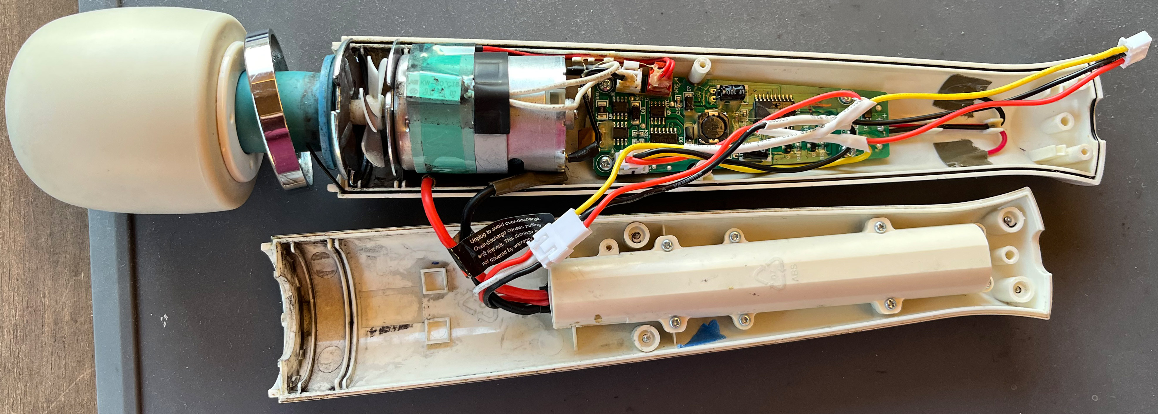
>just wire it straight to the battery with a linear pot in the way
Will I die if I do this or do I have to learn how transistors/relays work
Anonymous
10/22/2025, 8:45:23 AM
No.2952359
[Report]
>>2952363
>>2952336
>Will I die if I do this or do I have to learn how transistors/relays work
My pallet stacker literally works on this exact principle, except it has multiple switches and relays for different speeds. It's far from an efficient method of control, but it works. Definitely not worth it when you can get a basic motor controller and throttle for so little. Certainly less than the enormous variable resistor you'd need to handle enough power to get a bike moving.
Anonymous
10/22/2025, 8:51:37 AM
No.2952363
[Report]
>>2952367
>>2952359
Have to learn how relays/transistors work then. I already have a nice(chinese) throttle lever but I doubt it can handle 10 amps or whatever the battery puts out. Could I just use a lamp relay off an automotive store or some shit? I'm so fucking tired of ridiculous black box monstrosities for an application that is fundamentally "put the electrons through the coil bro"
Anonymous
10/22/2025, 9:41:07 AM
No.2952367
[Report]
>>2952369
>>2952363
>Could I just use a lamp relay off an automotive store or some shit?
sure, but you only get 2 speeds: off and max power
so, you actually need, at minimum, a PWM controller and some beefy mosfet transistors
fortunately, ESCs, as they're called, are varied and plentiful
so, it's no more complicated than lego
Anonymous
10/22/2025, 10:16:24 AM
No.2952369
[Report]
>>2952395
>>2952367
If it's just a DC motor, though, wouldn't limiting the voltage be enough for throttle? I'm not married to using the throttle lever I already have, do they sell linear pots that are beefier that I could control with a cable or some shit? (I'm imagining something like a spring-loaded barrel in a sleeve and the coverage area changes by moving it, so you yank it out and less power out like a slider dimmer switch in a wall)
Or is controlling motor speed by voltage just not a thing? I thought computers and the like PWM their fans because the mobos just suck and simply supply +5v all the time forever and rely on fans having their own controllers so the user doesn't have to adjust power curves for literally physically heavier or lighter fans.
Anonymous
10/22/2025, 1:01:14 PM
No.2952387
[Report]
>>2952328
>You connected the ground of your scope to live AC of the same reference. GG.
That's what I thought but I was measuring the full AC wave even with the ground disconnected. So that point must have been live and not neutral. The ground lead blew off when I touched the other output pin with it. But that must have been neutral, otherwise I couldn't have seen the AC earlier right? This is whats confusing me.
Anonymous
10/22/2025, 2:02:11 PM
No.2952395
[Report]
>>2952396
>>2952369
>Or is controlling motor speed by voltage just not a thing?
not in any high-power situation because
- heat: to lower a 500W motor to 250W, the resistor will have to dissipate 250W
- efficiency: 250W would be wasted as heat
- torque: lowering DC voltage reduces torque significantly - PWM maintains high torque even at low speeds
Anonymous
10/22/2025, 2:07:10 PM
No.2952396
[Report]
>>2952395
>PWM maintains high torque even at low speeds
troll physics irl
Anonymous
10/22/2025, 2:35:55 PM
No.2952399
[Report]
>>2952456
>>2952487
>>2952329
>even if that's the case for the scope, there's often other grounded equipment connected to the scope and ground can even come from a metal-cased scope sitting on other metal-cased instruments could even be table itself, e.g. metal arms holding up a grounded light fixture
and how would an isolation transformer help with that?
Anonymous
10/22/2025, 9:47:39 PM
No.2952456
[Report]
>>2952487
>>2952399
> how would an isolation transformer help with that?
there'll be zero volts between either of the two secondary transformer wires and earth ground
it would be as if the unit was battery-powered, except it's a 120Vac battery
Anonymous
10/22/2025, 10:45:17 PM
No.2952463
[Report]
>>2952487
I wish to drive q101 and q102 N-MOS power transistors via optocouplers. Their max Vdd is 5.5V. Upper opto supply is floating and the lower is referenced to +24V. Is it okay to power them like this?
Anonymous
10/23/2025, 1:37:23 AM
No.2952487
[Report]
>>2952669
>>2952399
You’d need to use the isolation transformer on all appliances with the shared ground connections, like a function generator plugged into its external trigger input, or a computer plugged into its USB or serial or GPIB port. Still, it’s kinda sketchy, because allowing you to clip the ground clip onto live voltages means you can easily touch those live voltages on the BNC connectors. Just take subtractive measurements from two probes instead, assuming you have the common-mode voltage range for it. If not, shell out for a differential probe.
>>2952456
There can’t be zero volts between both mains wires and anything. The point you’re trying to make is that there will be an arbitrarily high impedance path from the scope’s ground to any of the mains wires, and hence connecting them together won’t result in significant current flow. Clip it to live, and your ground is at live voltage. Clip it to neutral and it’s at neutral voltage. Clip it to the negative output of a full-bridge rectifier and it’s got a significant voltage with respect to both live and neutral, for half a cycle each, but still with no significant leakage current.
>>2952463
Looks fine to me. Haven’t seen anyone use an opotocoupling MOSFET driver before, any reason you aren’t using a gate drive transformer or photovoltaic gate driver? I assume that’s a flyback transformer with an air-gap?
If your FETs are meant to swap between two positive rails, I think Q102 is backwards. Its body-diode will constantly feed 24V into the load. Or is the intention to stop 36V from backfeeding into the 24V source, and you never want to feed the load 0V? Seems like a diode would work fine instead if that’s the case.
Anonymous
10/23/2025, 2:11:28 AM
No.2952490
[Report]
>>2952519
>>2952571
I started to disentangle my layout in between gooning sessions like
>>2951838 suggested, and it doesn't seem quite so bad. I think I might even try to do it surface-mount, even though I've only ever done through-hole stuff on stripboard before now. Does SMT actually make routing easier? I guess there are no features poking through the board to disrupt routing on the other side. I wonder if it might be too ambitious for my first SMT attempt, but I also don't really want to spend time making a "toy" practice project first.....
Anonymous
10/23/2025, 4:38:53 AM
No.2952517
[Report]
>>2952519
lend me your strength anons, this is just awful
Anonymous
10/23/2025, 4:46:02 AM
No.2952519
[Report]
>>2952523
>>2952490
SMD is easier because of that yes. But keep your connectors and other large/mechanical parts THT, SMT parts can rip off more easily.
>>2952517
Set your grid size to 0.1”/2.54mm anon! Or half of that. Also you can change resistor and diode footprints to be longer or shorter.
Anonymous
10/23/2025, 4:57:35 AM
No.2952523
[Report]
>>2952594
>>2952519
>Set your grid size to 0.1”/2.54mm anon!
Oh wow, that's an immediate improvement, thanks anon. I was wondering why my traces never quite lined up nicely kek
I'm trying to mimic other designs I've seen where the resistors end up nicely arranged in blocks. And surely there must be some advantage to being able to route traces underneath huge through-hole components.
Why don't electronics stores exist anymore bros? Do I really have to hit up amazon for shit like little plastic boxes and simple ass screw terminals? not even automotive stores carry basic switches anymore. i literally just need a fucking rocker switch for something and my only options are online i hate it here
Anonymous
10/23/2025, 1:30:12 PM
No.2952560
[Report]
>>2952640
are diy railguns/coilguns still a meme or did they die when people couldn't salvage caps from disposable cameras anymore
Anonymous
10/23/2025, 1:52:12 PM
No.2952561
[Report]
>>2952546
I rather order my shit online than wait in line forever to pay 20 times more for a component.
Fucking Conrad.
Anonymous
10/23/2025, 1:57:55 PM
No.2952562
[Report]
>>2952565
>>2952640
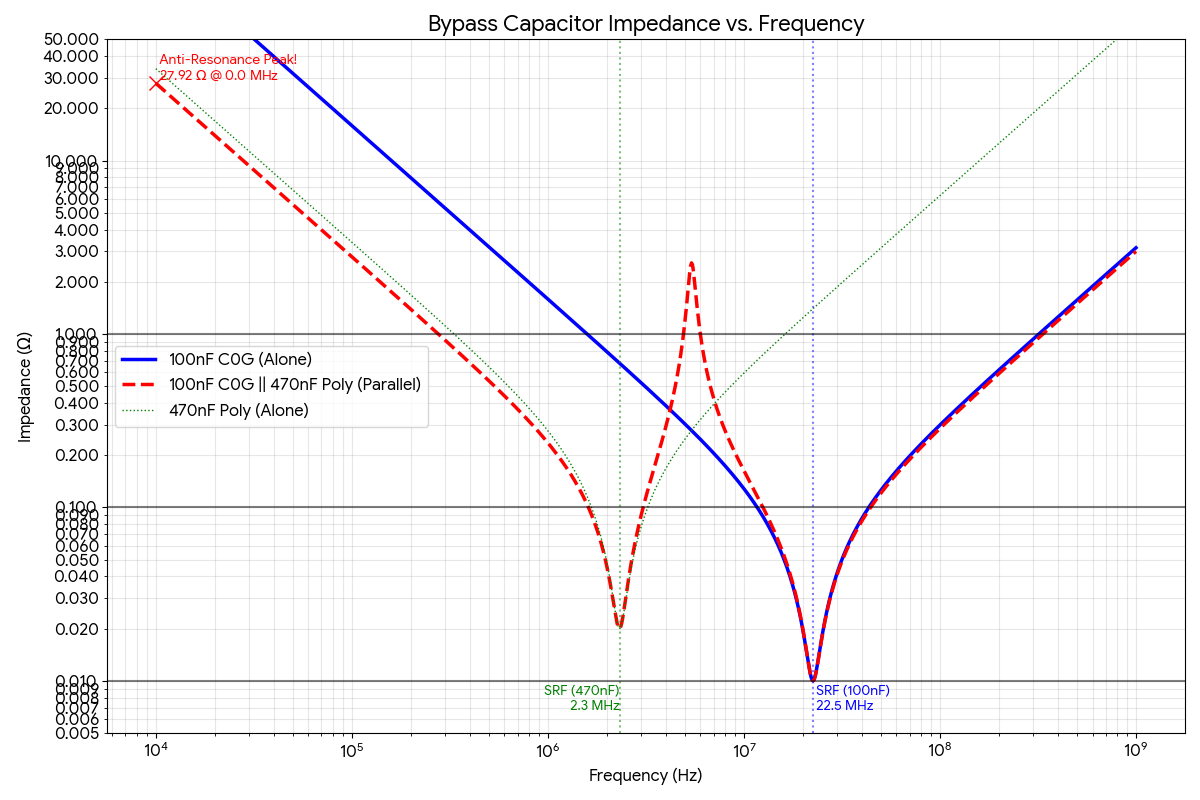
now got a pretty plausible looking answer from gemini 2.5 pro. this kind of info would be insanely difficult to decipher from forum posts and blogs and such.
Anonymous
10/23/2025, 1:58:56 PM
No.2952563
[Report]
Anonymous
10/23/2025, 1:59:58 PM
No.2952565
[Report]
>>2952562 (Me)
lol it labels the anti-resonane peak at 0.0 MHz which is fucked
Anonymous
10/23/2025, 2:30:48 PM
No.2952570
[Report]
>>2952546
yeah i wish i could just go to a corner store for random passives i need than wait for a digikey delivery
Anonymous
10/23/2025, 2:35:30 PM
No.2952571
[Report]
>>2952583
>>2952490
i believe you are synthanon right? i am rooting for you. i am working on my own synth project but have had so many setbacks in the past week that i want to throw my breadboard into the ocean. but i shall persevere
Anonymous
10/23/2025, 3:51:51 PM
No.2952583
[Report]
>>2952590
>>2952604
>>2952571
I'm self conscious that I'm recognisable on an anonymous mongolian basket weaving forum, but I guess these threads are so slow that it can't be helped
Thanks anon, seems that building some kind of synthesizer is a very popular kind of hobby project
Anonymous
10/23/2025, 4:47:17 PM
No.2952590
[Report]
>>2952604
>>2952583
sorry, i'll forget i ever even heard of you. serves me right, trying to make a friend...
Anonymous
10/23/2025, 5:14:59 PM
No.2952594
[Report]
>>2952523
with 50/25/12.5 mil grid you can easily squeeze tracks inbetween pins on 100 mil THTs
Anonymous
10/23/2025, 6:14:44 PM
No.2952604
[Report]
>>2952583
>>2952590
well this is awkward
Anonymous
10/23/2025, 9:00:53 PM
No.2952640
[Report]
>>2952654
>>2952546
I work at a Jaycar, they recently discontinued all their SMD parts because they didn’t sell. Good excuse to prototype with breadboards and perfboard, instead of just ordering an assembled PCB. The staff discount is great.
>>2952560
Because toy sized projectile shooters are pointless projects. It fires a pebble-sized projectile across the room, maybe even piercing a piece of cardboard. If you’re going to make a good coil-gun, you need much bigger capacitors, and probably not that high a voltage rating on them to make the coil winding less tedious. Same for railguns, but they’re so low voltage you can’t really find any low-impedance capacitor optimised for them. Either way it’s an expensive project, and the utility of being able to harm something is pretty limited. Compared to something that solves a problem, or allows you to create music.
>>2952562
Isn’t that the kind of data you should be able to get from a datasheet for each capacitor, then verify with spice or a bench test? Seems like adding higher-ESR bulk capacitance might be a better option, like an aluminium electrolytic or tantalum capacitor.
Anonymous
10/23/2025, 9:37:03 PM
No.2952654
[Report]
>>2952640
>Either way it’s an expensive project, and the utility of being able to harm something is pretty limited.
you don't need to be killing diplomats with one, but also we have ridiculous 100v ebikes with 9999999Ah batteries. Surely if people will pay for those kits, a few hundred caps off of DigiKey and a sawn apart steel bedframe are a drop in the bucket. Overbuilt nerf guns fell off too-- what if we combined them and instead of people embedding lead pellets in the foam (just far back enough to not hurt someone in a game!) to get more consistent ballistic performance, they banded their foam darts with copper?
>or allows you to create music.
very fair but a KORG keyboard, USB to MIDI cable, and a copy of SunVox are like negative ten dollars, people will pay you to take them, it's not a fair comparison
(also i was making a weird joke, i am lamenting the passage of time)
Anonymous
10/23/2025, 10:38:39 PM
No.2952669
[Report]
>>2952674
>>2952487
Thanks anon!
>any reason you aren’t using a gate drive transformer or photovoltaic gate driver?
I thought the idea could work in theory if the opto is fast enough. The rv1s9160 is very fast indeed. In my test circuit I put together on breadboard the opto (I presume?) caused lots of oscillations especially on the high-side N-MOS gate.
Yes, eventually some kind of switching power supply will be unavoidable. Probably a transformer supply with 3-4 outputs. But for now a lab supply and some linear regulators will do for testing purposes.
>stop 36V from backfeeding into the 24V source
Q102 is backwards exactly for this reason. In theory 0V at output should never happen. Replacing Q102 with a diode is a good idea but it might slow down the 36->24 transition too much when high-side N-MOS switches off. The low-side NMOS can conduct current in both directions when switched on, unlike a diode.
Anonymous
10/23/2025, 11:00:44 PM
No.2952674
[Report]
>>2952669
Schottky diodes can be faster than any silicon power MOSFET, because the MOSFET’s body diode isn’t a schottky. As far as I understand it, the only reasons to use a MOSFET as an ideal diode are to minimise voltage drop, and to handle higher currents. Oh and Schottky diodes also have highish leakage currents, which might matter.
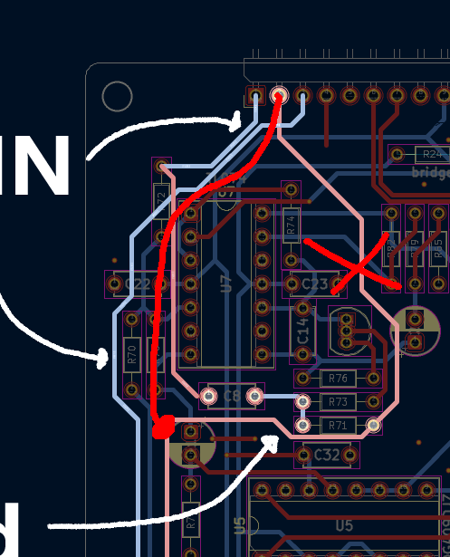
I've already used 10 vias just for this one small part, am I cooked or chopped or whatever it is the zoomers say nowadays?
I heard that you should avoid vias, but this is like that puzzle where you need to connect the 3 houses to water, gas and electricity but much much worse
Anonymous
10/24/2025, 2:45:30 AM
No.2952715
[Report]
>>2952718
>>2952724
>>2952707
Cmon anon, didn’t you formally study graph-theory like the rest of us? Just solve for the topology with the least manifold junctions.
I kid. Too many vias is bad, but snaky indirect traces are worse. A common heuristic for minimising trace snakiness is to have basically all the traces on the top layer be going in one direction (e.g. horizontally), and all the traces on the bottom layer be orthogonal to that. Not only does it do an alright job of minimising trace lengths, it should also make it easy to stitch together a cohesive ground plane between the traces.
Also I’d use thicker traces, you’re paying for all that copper so you might as well use it. Within reason, 50% thicker shouldn’t be any harder to route, but going as thick as the IC’s pads for the power rails might be preferable.
Anonymous
10/24/2025, 2:52:23 AM
No.2952718
[Report]
>>2952751
>>2952715
I heard that 0.5 mm was a good minimum trace width for through hole, and the ones in my pic are 0.25 mm. I guess I could go somewhere in the middle because they do look rather thin.
At the risk of blogposting, I'll also post the through-hole version of the same sub-circuit that I just finished. It took less than half the time and was SO much easier given that I can just route a trace underneath a THT resistor. I'm really torn about which paradigm to use now.
Anonymous
10/24/2025, 3:15:34 AM
No.2952724
[Report]
>>2952735
>>2952707
>I heard that you should avoid vias
that only really matters for high frequency (multi GHz), RF, etc stuff. for simple hobby boards, feel free to add as many as you need to keep your routing neat
also
>routed ground
i highly recommend that you use a dedicated ground plane so that you can avoid ground loops (resistance in your traces which causes the "ground" voltage to change across the board, very very bad!!).
since you're on a 2 layer board, the typical thing to do would be a polygon fill on your bottom layer that's all ground, and then trying to keep most of your signals on the top layer
a better practice, especially since you're doing analog, would be to use ground stitching, where you'd actually put a polygon pour ground on both of your layers, and then stitch the two together with a grid of vias. not strictly necessary, but it will help with signal isolation and as
>>2952715, you're already paying for the copper so you might as well use it all.
just be sure to check the "thermal reliefs for all components" thing if you're planning on soldering your components with a soldering iron rather than a reflow oven
Anonymous
10/24/2025, 3:27:04 AM
No.2952730
[Report]
>>2952731
Remember this thing from the last thread?
>>2952730
Well this is it now.
Anonymous
10/24/2025, 3:29:44 AM
No.2952732
[Report]
>>2952735
>>2952822
Anonymous
10/24/2025, 3:40:10 AM
No.2952735
[Report]
>>2952737
>>2953064
>>2952724
I think I get the concept, essentially you fill all the unused space and use it to provide ground connections everywhere, right? Only thing is that I noticed I'm already ending up with zones that are too cramped for the ground fill to penetrate...
>>2952731
>>2952732
Looks beautiful anon, I dream of achieving something like this maybe in the distant future. Looks like it needs a lot of trimmers though? What's your soldering method?
Also wow that was a fast turnaround
Anonymous
10/24/2025, 3:50:24 AM
No.2952737
[Report]
>>2952735
yep, make sure both the top and bottom layers are filled, your bottom layer is basically empty so it will act as a almost direct return path for any current.
you can also fill underneath U6 without causing any issues so hollowing out underneath it is unnecessary
unfilled areas are either too close to non-ground copper or they're islands, meaning they dont have a connection to the rest of the board's ground. a ground via to the bottom layer can usually fix this
Anonymous
10/24/2025, 3:51:11 AM
No.2952738
[Report]
Anonymous
10/24/2025, 4:24:32 AM
No.2952751
[Report]
>>2952763
>>2952718
THT is better for doing impromptu modifications to, and maybe a bit better for swapping passives out. Definitely better for locally sourcing a different sized capacitor because it doesn’t work properly with the one you designed it to use. Do you already have the parts? Do you intend for the fab-house to solder the parts in place?
Anonymous
10/24/2025, 5:06:10 AM
No.2952763
[Report]
>>2952771
>>2952776
>>2952751
I'll build the boards myself, and I am drowning in THT components, so to be honest, I'd like to have an excuse to use them, rather than start out from scratch with SMT. Although there are some IC's I'll have to get as SMT regardless, because they aren't available in DIP packages.
I only have a soldering iron and no hot air gun or hotplate, so I really feel like THT will make my life easier.
I just banged out another sub-circuit, I dare say I am getting the hang of it now. Most of my signals are fitting on the back side of the board so I think I will route +12 and -12 V along the top, if that's not too outrageous.
Anonymous
10/24/2025, 5:34:20 AM
No.2952771
[Report]
>>2952776
>>2952763
cant you use dip adapters for the smt chips and keep the pcb tht based
guess we're posting boards now
Anonymous
10/24/2025, 6:07:44 AM
No.2952775
[Report]
>>2952947
Anonymous
10/24/2025, 6:13:48 AM
No.2952776
[Report]
>>2952777
>>2952763
That sounds perfectly sensible.
>>2952771
He’s going to have to solder the SMT chip either way, might as well make it more compact.
>>2952773
Here's one of my many PCBs that I haven’t got around to actually assembling and using. It will come in handy eventually.
Anonymous
10/24/2025, 6:19:27 AM
No.2952777
[Report]
>>2952779
>>2952814
>>2952776
i use to put anime girls on our boards before my boss found one
Anonymous
10/24/2025, 6:24:15 AM
No.2952779
[Report]
>>2952781
Anonymous
10/24/2025, 6:30:10 AM
No.2952781
[Report]
>>2952814
>>2952779
this one didnt quite turn out the way i wanted it to
Anonymous
10/24/2025, 7:00:47 AM
No.2952785
[Report]
>>2952788
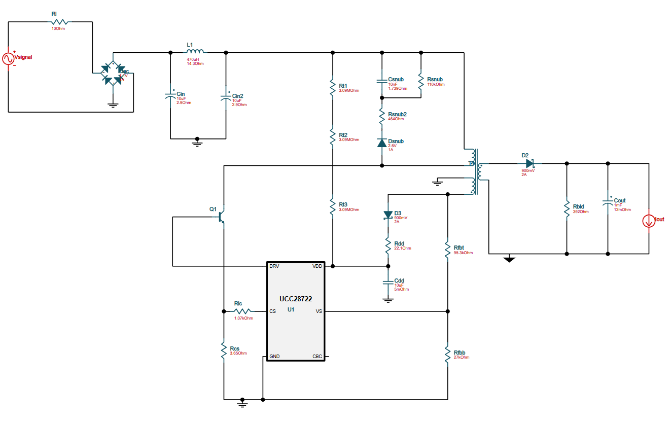
>>2952798
I recently got this circuit from TI Webench Power Designer. I tried simulating it on the trial version of PSpice for TI, but got the following error messages:
>ERROR(ORPSIM-15141): Less than 2 connections at node N00895.
>ERROR(ORPSIM-15141): Less than 2 connections at node GND_FU.
>ERROR(ORPSIM-15142): Node N01583 is floating
>ERROR(ORPSIM-15142): Node N01547 is floating
>ERROR(ORPSIM-15142): Node N01576 is floating
From what the netlist indicates,
>N00895 is connected to Rsnub.
>GND_FU is connected to the CBC pin.
>N01583 is connected to Rbld and the transformer's secondary inductor.
>N01547 is connected to the transformer's secondary inductor and D2.
>N01576 is connected to D2 and Rbld.
It doesn't seem like anything is incorrectly connected or missing (except for GND_FU, which I placed on the PSpice schematic because it wouldn't allow me get past the floating node error for the CBC pin).
Does anybody have any pointers on what I can do to fix this?
Anonymous
10/24/2025, 7:21:07 AM
No.2952788
[Report]
>>2952785
It looks like I was missing a ground connection after the transformer's secondary winding. That helped reduce down the simulation error messages to just the following:
>ERROR(ORPSIM-15141): Less than 2 connections at node N00895.
>ERROR(ORPSIM-15141): Less than 2 connections at node GND_FU.
I'm a total PSpice newbie (just installed it yesterday, as a matter of fact), so I got no idea whether these errors have something to do with component models or simulation settings.
Anonymous
10/24/2025, 8:27:42 AM
No.2952798
[Report]
>>2952785
Spice really wants all nodes to be referenced to a common ground node from what I’ve seen. If that downward arrow node is not the same as your other ground nodes, I’d definitely change that. As for the snubber, I’m not sure.
Anonymous
10/24/2025, 10:40:40 AM
No.2952814
[Report]
>>2952841
>>2952844
>>2952777
>>2952781
You nuisance you society you.
The use of copper is interesting, but I find green PCBs don’t give as much contrast as yellow. It’s also neat to use the solder mask layer for shiny parts, like I did with the YF-19 Valkyrie fighter here. Also based FLCL ho, did you do any Lains or Kinos?
Anonymous
10/24/2025, 12:38:08 PM
No.2952822
[Report]
>>2952731
>>2952732
beautiful. great job anon
how do I into SMD soldering when I can barely solder throughhole stuff
Anonymous
10/24/2025, 3:56:41 PM
No.2952839
[Report]
>>2952834
realize that everyone just cheats by using high-end paste and an even higher-end adjustible heat gun
Anonymous
10/24/2025, 4:16:38 PM
No.2952841
[Report]
>>2952921
>>2952814
heyyy are you the guy that made that macross-looking thing? thats what inspired me to try making the mamami.
is pic rel correct? or is it a 4-layer board? are those exhaust ports on the back also exposed copper like the cockpit is? JLC or PCBWAY?
Anonymous
10/24/2025, 4:19:14 PM
No.2952844
[Report]
>>2952921
>>2952814
lmao maybe i should read posts before replying to them.
>Also based FLCL ho, did you do any Lains or Kinos?
Lain would be cool, her show sucks but she's cute. never seen Kino's.
Anonymous
10/24/2025, 4:24:50 PM
No.2952846
[Report]
>>2952834
I just got one of those microscope screen things off amazon which helps with like TSSOP 16 packages but I have an MSOP-10 and it's pretty brutal. I think I'll get a hot plate or something
Anonymous
10/24/2025, 4:54:51 PM
No.2952848
[Report]
>>2952834
1.27mm pitch is easy as fuck imo. just use flux and the solder flows into place. keep your tip clean and tinned.
Anonymous
10/24/2025, 5:23:31 PM
No.2952856
[Report]
>>2952921
>>2952947
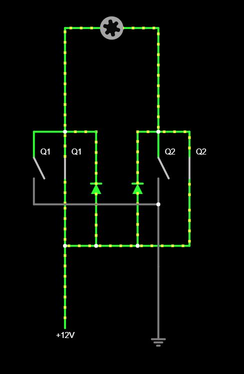
"in real life" how would something like pic related work when you power it down?
>kill PWM to T1 and T2
>LA and LB keep pushing current
>T1 and T2 blow the fuck up due to over voltage
Anonymous
10/24/2025, 7:57:42 PM
No.2952883
[Report]
>>2952896
>>2952834
i pay for a $10 stencil and use paste + my uni's reflow oven
i think you can technically reflow in a regular oven or with a hot air gun but i've never tried it before
hand soldering smd with an iron isnt too hard as long as your parts have exposed leads
Anonymous
10/24/2025, 9:06:21 PM
No.2952896
[Report]
>>2952883
you can also put a layer of fine sand in a pan on the stove if you really want to cheap out.
Anonymous
10/24/2025, 9:09:15 PM
No.2952897
[Report]
>>2952921
i've been in this hobby about a month and my brain feels stressed and weird. that's probably related to poor sleep as well but when will this shit finally get easy for me
Anonymous
10/24/2025, 10:35:06 PM
No.2952921
[Report]
>>2952947
>>2952841
Yeah I’m the creator. Just a 2-layer board, you can see it better in the light. The outline and vents are maskless board, the yellow-green parts are mask, and the majority is masked copper. With tinned and silkscreened highlights. It’s a traced picture from the wiki, but it took a while to condense the design down into just 5 tones. And the tones aren’t far from each other so you’re fighting uphill. Having copper behind non-copper layers could give you another colour or two, but they’d be even lower contrast, unless you’re lighting it up from behind. Could never get a good looking Break Blade Artemis mech tone map. But half-tones are a neat idea, I’ll have to look into how to optimise them for a PCB.
It’s JLC.
>>2952844
Kino is kino.
>>2952856
I think you’re meant to slowly ramp-down the on-time of the FETs. But maybe the energy when you turn it off hard would just slosh between either side of Lp Cp. Depends on the minimum current through the La/Lb inductors though. Spice sim it.
>>2952897
When you complete a project you can be proud of, the dopamine hit gets you hooked.
Anonymous
10/25/2025, 1:12:43 AM
No.2952947
[Report]
>>2952954
>>2952921
>And the tones aren’t far from each other so you’re fighting uphill. Having copper behind non-copper layers could give you another colour or two, but they’d be even lower contrast
its especially difficult when you dont actually know what the final tones will be
>But half-tones are a neat idea, I’ll have to look into how to optimise them for a PCB.
yea idk they might be cool for gradients but i couldnt figure it out. JLC can do 0.25 mm hatching, i might try that next time.
>>2952773
>>2952775
heres how this is going btw
>>2952856
flyback diode
Anonymous
10/25/2025, 1:55:57 AM
No.2952954
[Report]
>>2952947
> yea idk they might be cool for gradients but i couldnt figure it out
I think a half-tone between copper+mask and just mask would be too low contrast, same for tin+silkscreen depending on angle, while between mask and tin or silkscreen it would be too high contrast. Raw FR4 with copper or silkscreen would probably work well, but that green-beige colour is hard to use at the best of times. Tin should probably just be used sparingly as a highlight. Maybe using it for the outlines of a drawing would look good, it’s pitch-black from some angles and whiter than silkscreen from others.
>flyback diode
On La/Lb? So long as they don’t go negative under normal operation, that should work well.
Anonymous
10/25/2025, 5:37:27 AM
No.2952988
[Report]
>>2952993
>>2953447
Everything is spaghetti mess but the connections are made
I'm 50:50 on whether I throw it all out and start again. And next time I'll properly set the minimum trace width from the start
Anonymous
10/25/2025, 5:55:04 AM
No.2952993
[Report]
>>2953053
>>2952988
You can select everything, right-click and open up some sort of “narrow down your selection” dialogue, then deselect everything but traces. Then push “E” and change trace width for all traces at once. If you’re hiding inactive layers, it will only highlight what’s on the active layer.
Anonymous
10/25/2025, 3:50:59 PM
No.2953053
[Report]
>>2953126
>>2952993
I got most of the way there trying those menus, but I never got the option to change trace width, so I must have had something else selected too... I'll try harder to narrow the selection.
Having slept on this, I realise that my biggest problem was having a lot of quad op amps that were involved in quite different parts of the circuit. It was difficult to anticipate which op amps to assign to which footprint, but I guess this comes from experience. I think I'll have to re-shuffle which op amps belong to a common IC, so circuits end up closer together.
Do people make schematics with generic, footprint-less op-amps, and assign the footprint later? Maybe I just need to git gud...
Anonymous
10/25/2025, 4:02:18 PM
No.2953059
[Report]
>>2953126
Not sure if this is the right place to vent about this but of all controls I've tried repairing the nintendo switch pro controller is a massive piece of shit that constantly runs into issues where the contact pads im soldering or desoldering just decide to lift up off the board. I've never run into this issue on other controllers I've repaired and I'm stunned with how often I've dealt with this issue I can't find enough people complaining about the same issue, thus leading me to believe im the most at fault for constantly falling into this problem where the contant pads lift off on this specific brand of controller.
Im going to buy new soldering flux and see if that's the issue.
Anonymous
10/25/2025, 4:28:54 PM
No.2953064
[Report]
>>2952735
Thanks. I just pre-tinned the pads with solder wire, applied a liberal amount of high quality clear flux to each part and manually held the part in place with tweezers and let my hot air station do the rest.
Not the best way to do it, usually I would order a stencil for dense boards and apply solder paste that way.
Also KiCAD is the GOAT
Anonymous
10/25/2025, 4:53:23 PM
No.2953065
[Report]
>>2953066
>>2952731
What chip are you using on U1?
Anonymous
10/25/2025, 4:56:07 PM
No.2953066
[Report]
>>2953075
>>2953065
LM13700
Its used as a dual triangle osc core.
Only use NP0 caps for the timing or it wont work.
Anonymous
10/25/2025, 5:49:55 PM
No.2953075
[Report]
>>2953079
>>2953066
Is that to say that you need the NP0 caps for their temperature stability? Are you temperature compensating the exponential converter that determines volts/octave?
Anonymous
10/25/2025, 6:13:04 PM
No.2953079
[Report]
>>2953083
>>2953126
>>2953075
Not really, I did design it with the option to use a thermistor on the feed back for the opamp that drives exponential circuit.
The dialectic material for the NP0 caps have very low leakage leakage which is vital for this circuit because the timing cap is only 220pf and I expected the VCO to work down to 30Hz, with very little distortion. The result of this is that current control on the OTA is down to pA's for minimum frequency. This makes it very sensitive to leakage current, even surface contamination on the board can get it out of tune.
I had to wash the finished board under the tap and then drown it in alcohol to get it stable.
Anonymous
10/25/2025, 6:27:06 PM
No.2953083
[Report]
>>2953090
>>2953079
I see, that's good to know. Isn't there a risk that the v/oct tracking will drift due to temperature changes, then? I've seen old designs that use 3300 ppm/K tempco resistors, but it seems that nobody makes them any more and they are becoming rare.
I am cheating with my own saw core, the integrator gets directly reset by a clock signal from the Pico. The price I am paying for that is I don't think I can implement oscillator sync.
Anonymous
10/25/2025, 6:53:34 PM
No.2953090
[Report]
>>2953083
There may be risk of drift if I put it in my rack with other modules. But on the bench it stayed stable.
I guess I will see.
Anonymous
10/25/2025, 8:22:02 PM
No.2953112
[Report]
>>2953126
>>2953127
you're the only wizards I can ask this, I have a multimeter that's been working alright, I only had to change the fuse once because I did a stupid, but that was almost six months ago.
The issue, out of nowhere when I put it on any set it starts reading without even having the leads connected. And when I test something, it either doesn't detect it or jumbles around.
The fault readings are small, even for the smallest measurements I have (2000microA).
It may be a stupid question, but I'm concerned because it's never done that
Anonymous
10/25/2025, 8:42:15 PM
No.2953116
[Report]
>>2953119
>>2953180
>only FOSS option for wiring harnesses is wireviz
>it's entirely text based python dogshit
why are csniggers like this?
Anonymous
10/25/2025, 9:08:51 PM
No.2953119
[Report]
>>2953206
>>2953116
If you want quality then pay for it, or Do It Yourself my negro.
Anonymous
10/25/2025, 9:25:21 PM
No.2953126
[Report]
>>2953132
>>2953053
I at least choose my op-amps early, and often have to shuffle them about 2 or 3 times when laying out the traces. It’s pretty easy to swap them around so I do it whenever it might help.
>>2953059
Is it taking longer to work on each pad than other controllers? Delaminating traces is mainly a function of time and temperature, but also of force. Pads with lots of heat sinking to a copper pour will take longer to heat up, not only putting more heat into the pad, but also increasing the likelihood that a desoldering operation moves the part too soon and puts force on that pad. Having thermal reliefs and oversized pads and traces helps strengthen the lamination, but the best solution is to minimise time.
>>2953079
I was under the impression that film caps were lower leakage, especially if you put 4-5 1nF caps in series due to lack of smaller values. I know the X2 caps I bench-tested had incredibly low leakage.
>>2953112
Take it apart and see if there’s gunk in the range-switch. Ideally wash it down with IPA, treat any corrosion, and add some fresh dielectric grease back to the range-switch contacts. If it’s an issue on all ranges like that, the issue is going to be closer to the ASIC than the plugs. Maybe it’s something going on with the power rails, or the passives before the ADC input(s). But if it’s one of those chips with a different analogue input pin for each range, and a different trace going to each one, then the most likely case is that the problem is at the only common point of all the faulty measurements: the chip itself.
Anonymous
10/25/2025, 9:25:54 PM
No.2953127
[Report]
>>2953112
>I'm concerned
your meter's fine
there's some electromagnetic paranormal activity in your crib
build a faraday cage if it bugs you
but readings from floating leads dont matter anyway unless you're hunting ghosts
Anonymous
10/25/2025, 9:48:36 PM
No.2953132
[Report]
>>2953141
>>2953126
>059
I have noticed that the switch pro controllers have particularly "worse" factory solder but once i put leaded solder onto the pads it starts to pool like any other solder within milliseconds. I mentioned the flux thing earlier cause I saw a forum post where someone mentioned it, well I grabbed the hand me down flux my dad gave me and no where on the packaging does it say "for electronics". I feel like an idiot but I really hope i figured out what was causing these constant failures. If it was the flux being too strong I'm surprised at how resilient other controllers are compared to these newer nintendo controllers.
Anonymous
10/25/2025, 10:47:32 PM
No.2953141
[Report]
>>2953147
>>2953132
Wait you’re not using zinc chloride plumbing flux, are you?
Anonymous
10/25/2025, 11:11:23 PM
No.2953147
[Report]
>>2953141
Erm........
I think it's a miracle I soldered with this crap for so long up until now.
Anonymous
10/25/2025, 11:44:22 PM
No.2953156
[Report]
>>2953186
>>2951482 (OP)
I am in the market for 12volt lithium ion battery packs. Can anyone recommend some brands so I don't get ripped off of cheap junk.
I'll be using the battery pack to run LED tail lights, brake light, turn signals and horn on a dirt bike. I have been looking at 3 and 6 cell 18650 battery packs. I was thinking to get either two 3 cell packs that I can swap around as one is charging or may maybe just one 6 cell pack.
Any suggestions on this are appreciated.
Thanks.
Anonymous
10/26/2025, 2:01:53 AM
No.2953180
[Report]
>>2953183
>>2953116
a friend of mine was working on a wiring harness plugin for freecad a while back. not sure if anything came of it
Anonymous
10/26/2025, 2:19:44 AM
No.2953183
[Report]
>>2953187
>>2953180
WOW thanks for the useless anecdote, buttfucker.
Anonymous
10/26/2025, 2:32:09 AM
No.2953186
[Report]
>>2953201
>>2953156
If you care about longevity, go for 4S LiFePO4. 30% Less energy dense, but they should be able to handle three times the charge-discharge cycles. Just don’t charge them below freezing.
People already make and sell 12V LiFePO4 batteries in the same form-factor as SLA batteries (e.g. 4.5Ah, 7.2Ah, 12Ah, 18Ah) with built-in BMS circuits and all in a waterproof case with convenient terminals, but they’re even less energy dense since they usually have empty space to give them the same capacity as a lead-acid.
I don’t trust no-name lithium batteries, but the lipos made by chinky brands like CNHL seem solid, and there’s plenty of people using them for you to find some reviews. /diy/‘s own remote control general might be worth asking about packs, even if you’re not planning on using a lipo.
Anonymous
10/26/2025, 2:32:40 AM
No.2953187
[Report]
Anonymous
10/26/2025, 2:38:08 AM
No.2953189
[Report]
>>2953204
Can you guys help me with an exercise? When the secondary winding of a 120V/240V transformer is open, the primary current is 0.3A for a power factor of 20%. The transformer specification is 4KVA. Calculate: a) the maximum load current IP. b) The no-load excitation current IE. c) The core loss current IH. d) The magnetizing current Im.
My answers are: a) 33,33 A b) 0,3 A c) 0,06 A d) 0,294 A
Are my answers correct? help me.
Anonymous
10/26/2025, 2:13:47 AM
No.2953201
[Report]
>>2953186
Thanks for the info. The tip to not charge in freezing temps will likely save me some grief. I live in a cold climate and likely would have charged monthly in an unheated garage. I'll plan to bring the batteries inside for the winter.
>/diy/‘s own remote control general
Nice I'll check it out. I was looking at RC batteries. I don't much about them. They look pretty durable.
Anonymous
10/26/2025, 2:25:40 AM
No.2953204
[Report]
>>2953210
Anonymous
10/26/2025, 2:28:02 AM
No.2953206
[Report]
>>2953343
>>2953119
okay i actually tried it out and it's not so bad once you set it all up. the auto BOM feature is nice
it's a lot better than using something like draw.io, but i really wish it was GUI based rather than YAML
Anonymous
10/26/2025, 3:07:59 AM
No.2953210
[Report]
>>2953231
>>2953204
Thanks man. But let me ask something. If I add the IH with the Im the total is 0,354 A. However the Ip is 0,3 A. Is this really correct? Should the sum of he IH with the Im be equal to Ip, which is 0,3 A? Or am I misinterpreting something here?
Anonymous
10/26/2025, 4:23:12 AM
No.2953231
[Report]
>>2953210
here's a hint: IH is in phase with the voltage, and Im lags the voltage by 90 degrees
Anonymous
10/26/2025, 8:33:41 PM
No.2953343
[Report]
>>2953206
here is something GUI based
>why is there no app, reeeee
I'm designing an LED lamp and interested in 2835 LEDs. Is it even possible to solder those by hand? Soldering iron or hot air?
Anonymous
10/26/2025, 9:28:51 PM
No.2953360
[Report]
>>2953569
>>2953356
yeah, the leads are exposed and LED itself is pretty big. shouldnt be too different from hand soldering any other kind of SMD passive.
Anonymous
10/26/2025, 9:29:02 PM
No.2953361
[Report]
>>2953569
>>2953356
>2835
that's positively YUGE. hand-soldering shouldn't be a problem
Anonymous
10/26/2025, 9:49:12 PM
No.2953362
[Report]
>>2953569
>>2953356
They are big enough to hand-solder sure, but the size of the copper pour (and any aluminium/copper heat-conductive backing to the PCB) could make it difficult. Also the LED from your chosen manufacturer may have less of a hand-solderable pad, those LED packages vary depending on maker. A reflow plate would be my ideal choice.
What’s the design like? LVDC, or are you going for high-series chips running off mains? Dimming? Multiple colours/whites? Custom diffuser?
Anonymous
10/26/2025, 10:10:50 PM
No.2953363
[Report]
>>2953399
>>2953420
how the hell do i get a fuse block that takes blade fuses (things that im using are 2a, 10a and 20a) and doesnt lie about its amperage? I've been looking for one for the past 3-4 hours and found nothing. Does such a thing just not exist?
Anonymous
10/26/2025, 11:15:36 PM
No.2953377
[Report]
>>2953382
>>2953356
you want to dissipate the heat and ordinary FR4 might lead to components autodesoldering depending on your use case
Anonymous
10/26/2025, 11:36:09 PM
No.2953382
[Report]
>>2953377
don't say silly things to anon. FR4 is fine if you know what you're doing
Anonymous
10/26/2025, 11:42:06 PM
No.2953383
[Report]
>>2953569
>>2953356
...when you have a cooling surface to dissipate the heat from running them continuously without getting them desoldered you must have a really powerful iron or preheat that big cooling surface. It is hard if you don't know but easy if you know how to overcome the issue.
Anonymous
10/27/2025, 12:44:55 AM
No.2953399
[Report]
>>2953363
Yeah I’ve noticed the same thing. Where I work we sell those, but also some 200A Midi fuse holders with M4 terminals.
Maybe there are aftermarket fuse boxes designed to be installed in cars?
Anonymous
10/27/2025, 1:49:40 AM
No.2953420
[Report]
>>2953363
>amazon
if you want accurate current ratings, buy from an actual distributor
amazon nowadays is arguably worse than aliexpress desu
>>2952988
I threw the entire "design" out and started again and I think I ended up with something better, although I still had to resort to vias in a few places. Thanks for reading my blog but I figure if I post a picture then maybe someone might catch an outrageous error just by chance.
Anonymous
10/27/2025, 6:56:31 AM
No.2953465
[Report]
>>2953536
>>2953646
>>2953447
What’s the grounding story? Those 300pF caps are terminated in nothing so I’m guessing there’s a ground-plane that’s hidden? If so, post with the ground plane(s) visible and ground traces highlighted. You might need edge-cuts for it to fill in properly. I’m worried you may have a discontinuous ground plane, the remedy to which would be via stitching with two-sides planes, or a plane on one side and stitching traces on the other side.
Also narrow TO-92 transistors are a bit prone to solder bridges, you could consider a non-inline footprint, or a wide footprint, or both.
I take it you’ve done a DRC check? It often screams about overlapping silkscreen if you’re doing that. If not there’s an addon to hide all reference designators at once. But reference silkscreen is handy, I like to add simplified circuit diagrams or boxes showing circuit blocks to help the inevitable future troubleshooting also.
>>2953447
that SO16 boi on top could be moved quite a bit down
you can save space by using vertically mounted throughhole resistors. there's a footprint for that
looks like you have a ground plane like the other anon said, but which trace(s) are the positive supply?
Anonymous
10/27/2025, 11:11:34 AM
No.2953485
[Report]
>>2953646
>>2953447
oh and 4 layer boards are quite cheap nowadays, especially if you only use plated through holes (no blind or buried vias). consider giving routing with 4 layers a try. I find it pleasing
Anonymous
10/27/2025, 4:11:57 PM
No.2953536
[Report]
>>2953465
>>2953484
>>2953484
Let me post an updated version in a bit with the ground plane done, I was only 95% of the way there. And I need to put a connector at the top. Thanks anons
Anonymous
10/27/2025, 4:41:24 PM
No.2953539
[Report]
>>2953447
damn i'm not looking forward to doing all this shit when i'm ready for pcb design
Anonymous
10/27/2025, 8:07:09 PM
No.2953569
[Report]
>>2953360
>>2953361
I'm just a bit worried if the only thing I manage to melt is the plastic package itself
>>2953362
It's a battery powered lamp with 2xAA batteries, boost converter. LED configuration will be either 1S-3P or 2S-3P depending on certain factors.
>>2953383
What if I use 0.1 W or 0.2 W 2835 LEDs and thermal reliefs?
Anonymous
10/27/2025, 9:14:19 PM
No.2953584
[Report]
>>2953447
looks good, but i would be a bit worried about how split up your ground plane is
maybe consider going to 4 layers and using your inner layers as ground/power or ground/ground. it'll cost a bit more though
Anonymous
10/27/2025, 9:53:07 PM
No.2953592
[Report]
>>2953609
>>2953776
i have a pair of unkown diodes on a pcb which use i dont really understand
the diode has that print on it
---
V6
58
google doesnt show shit, do these numbers mean anything?
Because what they do is beyond me also why they chose to have both motor terminals on 12v in idle
Anonymous
10/27/2025, 10:51:16 PM
No.2953609
[Report]
>>2953611
>>2953592
Do you know which package is it? Are there any other markings on the device?
Anonymous
10/27/2025, 11:12:29 PM
No.2953611
[Report]
>>2953776
>>2953609
just measured it, SMA DO-214AC
no other markings beisde the diode line
Anonymous
10/27/2025, 11:26:19 PM
No.2953617
[Report]
>>2953634
i feel like i've hit some weird demotivational plateau and i only started a couple weeks ago. i was very happy breadboarding some things and getting results...but now i don't know where to go. i don't think i'm ready for pcb design but i lose interest when my breadboarding gets too complex
Anonymous
10/28/2025, 12:59:56 AM
No.2953634
[Report]
>>2953636
>>2953617
>i lose interest
this is pretty common for people who need instant gratification
suggest you switch hobbies
porn is a good alternative
you can still do electronics once you're satiated and your dick is sore
works for me
Anonymous
10/28/2025, 1:14:33 AM
No.2953636
[Report]
>>2953634
that might be part of it. anyway i soldered some of my breadboard shit onto perfboard and feel a little better now
>>2953465
>>2953484
>>2953485
I did a ground fill on the front and back sides and the DRC didn't complain that anything was unconnected, so I think I can get away with it if I scatter some vias here and there to join the front and back ground planes together? I will also add dedicated ground returns for a couple of clock signals, and also the top right IC communicates via SPI so that's why it's as close as possible to the connector pins.
I will work on the silkscreen now, I won't be able to fit component values and designators so I think I'll just have designators under the footprints.
The idea is that 4 of these will plug in to a baseboard with pin sockets that I'll make from strip board.
I'm not sure if this looks overly ambitious, especially for a first attempt. I have breadboarded all this though, and it does work.
Anonymous
10/28/2025, 1:47:34 AM
No.2953651
[Report]
>>2953652
>>2953646
is it audio or high frequency stuff? I'm guessing the former. with RF the rules around ground pour become complicated for impedance reasons
the left and right sides of the board look nicely separated
double-check that your DRC rules match what your board fab can do. this doesn't look terribly complicated, but still
Anonymous
10/28/2025, 1:55:07 AM
No.2953652
[Report]
>>2953654
>>2953651
It's nothing sophisticated, all audio signals <4 kHz or so. If it works on breadboard with janky wires flying everywhere I'm hoping that I don't have to be too stringent for this. The SPI interface concerns me the most, which is why I minimized the length of traces going to that IC - it's an 8-channel DAC which will be generating control voltages to send to all the other components (down that central kind of bus of connections)
Anonymous
10/28/2025, 1:56:33 AM
No.2953653
[Report]
>>2953646
oh and you can toss vias here and there to help stitch the ground planes together
on higher-speed boards one often dedicates entire layers to either power and ground. the distance between them forms a capacitor which helps with decoupling
Anonymous
10/28/2025, 1:58:29 AM
No.2953654
[Report]
>>2953657
>>2953652
ah well no worries then. yeah the SPI bus is your main concern. you might want to think about termination since you have multiple cards and a backplane, and the SPI can run quite fast. there's many methods to prevent reflection - termination at the edges, series resistors on the clock and data lines etc
Anonymous
10/28/2025, 2:16:07 AM
No.2953657
[Report]
>>2953660
>>2953800
>>2953654
I've heard that I can put low-value resistors on the transmission end of the SPI lines, so I plan to do that. I'm also going to run it at 1 MHz to mitigate the less-than-ideal circumstances of strip board, pin header connections, etc
Anonymous
10/28/2025, 2:29:48 AM
No.2953660
[Report]
>>2953657
sounds good. I did similar things with RS-485
Anonymous
10/28/2025, 7:54:34 PM
No.2953776
[Report]
>>2953592
>>2953611
Maybe it's an FES2J
>>2953657
> I've heard that I can put low-value resistors
Technically, your conductor length should be an exact multiple of the wavelength for best results.
Anonymous
10/28/2025, 9:52:18 PM
No.2953805
[Report]
>>2953809
Anonymous
10/28/2025, 9:54:19 PM
No.2953807
[Report]
>>2953848
>>2953864
I'm about to order parts from Mouser. mostly IEC C14 connectors and fuses. thinking of random things I might order while I'm at it but so far I could only think to order more flux. any ideas?
I might also order some low tempco resistors (but not expensive vishay ones)
Anonymous
10/28/2025, 9:54:24 PM
No.2953808
[Report]
>>2953800
>10 MHz SPI
>wavelength = 3E+08/1E+07
an exact multiple of 30 meters?
Anonymous
10/28/2025, 9:55:58 PM
No.2953809
[Report]
>>2953800
this very much depends. for example one can put in stubs to effect termination. but this is only practical at VHF and above. UHF really.
>>2953805
don't listen to him
Anonymous
10/28/2025, 11:58:38 PM
No.2953848
[Report]
>>2953858
>>2953807
what kinda shit do you make or want to make
Anonymous
10/29/2025, 12:19:03 AM
No.2953853
[Report]
>>2953855
>>2953859
i don't know where else to post this but i'm slowly reading more about diy ham radio transceivers and it's very impressive that these boomers are building 7+ mhz circuits on double sided copper clad. compare this redditors saying you NEED a four layer stack up to blink an led at 10 hz and also WHY would you even want to make your own pcb when china can do it for so CHEAP.
Anonymous
10/29/2025, 12:23:33 AM
No.2953855
[Report]
>>2953853
redditors rarely speak from experience i've learned. they just regurgitate things they believe are wise, but don't know what the fuck they're talking about.
Anonymous
10/29/2025, 12:30:41 AM
No.2953858
[Report]
>>2953848
two things:
1) a programmable heat for my house. raspberry pi controlled, solid state relay. schedules heating when electricity is cheapest based on a thermal model of the basement
2) thermometry stuff for uni
Anonymous
10/29/2025, 12:31:45 AM
No.2953859
[Report]
>>2953957
>>2953853
7 MHz isn't anything special. it's also narrowband. whereas digital spews crap all over the spectrum, which you'll want to keep under control
Anonymous
10/29/2025, 1:05:23 AM
No.2953864
[Report]
>>2953807
you can never have too many Compton valves
I bought a hitachi rechargeable secondhand that had an old 7.4V LiPo battery that needed replacement, which I did with one of those fancy titan brand batteries meant for airsoft. I charged the battery up using the Titan lipo charger meant for the battery before putting it into the hitachi wand to test. It does function, as in it vibrates and changes vibration speed and mode, but is it safe to charge it using the wand's cable?
From what I can tell, the wand uses an A308 (the 14-SOIC package) charge monitoring IC and a MEM2309 P-Channel MOSFET to switch current to and from the battery. (
http://insidesextoys.com/magic-wand)
The charger cable seems to operate at 10V.
The battery is this one:
https://www.amazon.com/Lithium-Ion-Airsoft-Battery-Capacity-Performance/dp/B0821K767Y
>>2953929
It will probably charge, at least once. But those are different battery types, so no. Even if they're the same chemistry, the charging profiles vary. Also the built in BMS is probably trash compared to a proper Titan charger. I would retrofit some pogo pin connectors onto it.
Anonymous
10/29/2025, 9:19:58 AM
No.2953938
[Report]
>>2953941
>>2953935
Good point. I guess the safest option is to allow it to be charged using the titan power charger. If I do this, I was thinking or replacing the rear jack with a JST terminal that connects to the battery as well as the PCB's terminal (where the battery used to be connected). Is it safe for the PCB to expose it to the current of the charger like that?
Anonymous
10/29/2025, 10:02:29 AM
No.2953941
[Report]
>>2954119
>>2953938
>is it safe for the PCB to expose it to the current of the charger like that?
probably
you can compare DC voltages from both sources
if not close enough, consider using a switched barrel jack that disconnects PCB when anally penetrated
Anonymous
10/29/2025, 1:18:56 PM
No.2953957
[Report]
>>2953982
>>2953859
are you referring to square waves having an infinite bandwidth due to fourier expansion representation? how true is this considering real world square waves have a non-zero rise and fall time?
Anonymous
10/29/2025, 4:00:26 PM
No.2953982
[Report]
>>2953957
it's not infinite for obvious reasons but it's high enough that you have to keep it in mind
Anonymous
10/29/2025, 5:11:27 PM
No.2954000
[Report]
>>2954064
Anonymous
10/29/2025, 5:41:34 PM
No.2954009
[Report]
Hi /ohm/, i'm trying to learn about robotics, and I don't want to replay on /robo/, I'm into manufacturing robot arms like Fanuc or ABB. Recently I started a small project for a steward platform and I like it, I wanna work in a factory programming and maintenance some Fanuc or any shit like that, anyone know a free course to start in Fanuc or piracy them
Anonymous
10/29/2025, 8:37:24 PM
No.2954042
[Report]
>>2954078
>>2952707
Having lots of different sized vias, or difficult to manufacture aspect ratios (narrow radius / thick pcb), or more specialised vias (buried, blind, in pad) does drive up cost.
There is probably a larger jump in cost going from 0 vias to 1 via, vs. 1 via to 100. Typically the setup cost is a lot, but once they have it set up its pretty cheap to automatically drill more holes.
Anonymous
10/29/2025, 9:12:42 PM
No.2954053
[Report]
>>2954078
>>2952707
unless you plan on drilling the boards yourself, vias isn't a huge issue as the other anons pointed out. I actually designed my own 160x100 eurocard with 100 mil hole grid and sent it to jlcpcb with another order rather then buying boards from the usual places. ended up cheaper
Anonymous
10/29/2025, 10:01:37 PM
No.2954064
[Report]
>>2954000
Because $60 (item + parts) is cheaper than $200+ and it works well enough.
Anonymous
10/29/2025, 10:48:09 PM
No.2954078
[Report]
>>2954086
>>2954115
>>2954042
>>2954053
I actually got too scared of SMT and designed it as through hole, this is me:
>>2953646 although some ICs were only available as SMT.
I am about to pull the trigger on ordering the board, but I'm having second thoughts about how careful I need to be about my signals interfering with each other. This is all audio frequency, but there are some square wave "clock" signals that come into the board to control my oscillator circuits, and I'm not sure if I can return those signals through the ground pour, or if they need their own, dedicated ground.
They are 4 kHz square waves, but it was pointed out to me that of course a square wave contains harmonics at much higher frequencies. Then again, I'm only interested in the audible output, so surely I could send them through a passive RC filter with a cutoff frequency in the 100s of kHz and be free from electromagnetic infetterence in the MHz range?
Anonymous
10/29/2025, 11:25:36 PM
No.2954086
[Report]
>>2954090
>>2954078
>This is all audio frequency
>but there are some square wave "clock" signals that come into the board to control my oscillator circuits
>They are 4 kHz square waves
>but it was pointed out to me that of course a square wave contains harmonics at much higher frequencies
>Then again, I'm only interested in the audible output
>so surely I could send them through a passive RC filter with a cutoff frequency in the 100s of kHz and be free from electromagnetic infetterence in the MHz range?
Anonymous
10/29/2025, 11:35:51 PM
No.2954090
[Report]
>>2954094
>>2954086
thanks anon, this post helped me understand the situation a lot better
Anonymous
10/29/2025, 11:47:35 PM
No.2954094
[Report]
>>2954096
>>2954090
lol im sorry anon, unless youre
>>2951499 in which case you deserve it for ignoring my first post.
can you _briefly_ describe what the circuit is doing and what the clock is for?
Anonymous
10/30/2025, 12:12:56 AM
No.2954096
[Report]
>>2954100
>>2954124
>>2954094
An audio frequency PWM signal is differentiated by C7 and R3, and the resulting spikes at the base of Q1 discharge integrator capacitor C6. So the output of U1C is a sawtooth wave whose frequency is determined by the square wave input.
I also want to buffer and offset the square wave to send to the rest of the circuit, which is fairly classical analog synth territory - it has a voltage controlled filter and a voltage controlled amplifier. The output is audio between 50 - 4000 Hz.
But I understand that the square wave from the Pi will contain all these very high frequencies because the rise/fall time is measured in nanoseconds. And I know that interference is more of a problem with high frequencies. My SPI interface however is well separated from all of this audio stuff, in the top right of the board.
Maybe I am just overthinking it. I've heard a lot of stuff about separating signal ground and power ground, but it's not like I'm driving a motor or something
Anonymous
10/30/2025, 12:48:09 AM
No.2954100
[Report]
>>2954103
>>2954129
>>2954096
>The output is audio between 50 - 4000 Hz.
the relevant information is the amplitude of the audio, not the frequency
if you're in the volts, you can mix audio and digital as much want
if in the millivolts, you may have a disaster on your hands
and, BTW, filtering wont help, coz sharp waveforms simply jump over components like a kangaroo on a trampoline
Anonymous
10/30/2025, 12:57:23 AM
No.2954101
[Report]
>>2954199
>>2954207
why is the left version of the colpitts oscillator (CLC) unpopular compared to the right version (two capacitors with grounded midpoint, parallel to inductor)?
Anonymous
10/30/2025, 1:15:15 AM
No.2954103
[Report]
>>2954129
>>2954100
>the relevant information is the amplitude of the audio, not the frequency
oh, I see. The SPI at the top of the board will be 0 to 3.3 V, and the audio is -5 to +5 V. I would hope that the loudness of the audio signal is going to swamp any interference I happen to pick up. Having said that, at the inputs of the LM13700s the signal is attenuated to about 30 mV by resistor dividers before being amplified again by the OTA.
I can't say I've ever had interference problems on strip board or bread board, but PCBs are new to me and so is the mixing of analog and digital worlds. Pic related is the prototype. I would have thought that if my signals survive in this mess then surely any kind of PCB has to be better, even if designed by a total noob
Anonymous
10/30/2025, 1:32:05 AM
No.2954108
[Report]
>>2954119
>>2953929
>>2953935
I don’t know, that TI charge monitoring chip sounds pretty fancy. Worst case you can change a resistor or two to set the cutoff voltages to different values. But I’d investigate if there’s any cell balancing going on too. And also where the constant-current is coming from.
Anonymous
10/30/2025, 1:49:37 AM
No.2954115
[Report]
>>2954078
shove the last bit of the ground return on the clock to the lft so you don't make a big 'ol loop there. you might need to move some of the other signals too of course. I believe in you anon
Anonymous
10/30/2025, 2:05:45 AM
No.2954119
[Report]
>>2954215
>>2953929
>>2953935
>>2953941
>>2954108
Little late now, but I made a new wiring harness and took out the back plug to use the JST connector so that it charges using the titan charger. The polarity of the JST connectors on the charge side and the discharge (motor power) side are reversed, but it seems to work, I guess because the PCB has enough protective diodes in it. Not willing to test what happens if I run it while charging though.
Anonymous
10/30/2025, 2:26:37 AM
No.2954124
[Report]
>>2954127
>>2954096
>An audio frequency PWM signal is differentiated by C7 and R3
unrelated but i think your differentiation drawing is missing half of the differentiation.
>The output is audio between 50 - 4000 Hz
no sir. the CLOCK may be 50 - 4000 Hz, but if you generate a 4 kHz sawtooth and filter out everything above 4 kHz, its just going to sound like a sine wave. the higher-order harmonics are precisely the difference between a sine wave, square wave, triangle, sawtooth, etc. you need to keep them. also if you generate any wave above about 10 kHz theyll all sound identical because the 2nd harmonic will get pushed out of human hearing range. give it a try
https://onlinetonegenerator.com/
>But I understand that the square wave from the Pi will contain all these very high frequencies because the rise/fall time is measured in nanoseconds.
the sawtooth will contain the same harmonics. more, even. i really wouldnt work about it too much. if it helps you sleep better, know that a piece of metal works better as an antenna if it sees a high impedance load. pin 14, for instance, will never pick up interference, but pin 13 might. lowering R6 and R7 would help. and for gods sake do a fucking ground pour. you dont need a separate return path.
>And I know that interference is more of a problem with high frequencies.
thats a very strange thing to say for someone whos trying to build a synth circuit and lives in a world with 60 Hz power distribution and free automatic lowpass filters built into every human ear.
>I've heard a lot of stuff about separating signal ground and power ground
if youre below 1 amp just forget it.
>I also want to buffer and offset the square wave to send to the rest of the circuit
you might want to double check your wiring of U1B; you have feedback going to the non-inverting input. same for U1A and U1C... what the hell is this circuit even? did you build this? does it work?
Anonymous
10/30/2025, 2:45:56 AM
No.2954127
[Report]
>>2954129
>>2954124
Anon, you have saved me from a grave mistake, thank you. I was rearranging op amps on my schematic to make them associated with convenient positions on the PCB, but I neglected the fact that they weren't all drawn in the same orientation. So a bunch of them will be upside down now, and I need to re-check the schematic. The whole circuit works on the breadboard, but the op amps in the schematic got scrambled due to my carelessness.
I did a ground pour on both layers, I just turned the opacity down so it's not so visible. Seems like I am overthinking that aspect. This pic has the opacity turned back up and with some vias I think I will have good ground connectivity everywhere.
Your explanation of harmonics makes sense and I realise I've been thinking of the concept of frequency a bit wrong. I understand better now.
Thanks for taking the time to write that post. I'm optimistic about this once I can unfuck my op-amps.
Anonymous
10/30/2025, 2:58:02 AM
No.2954129
[Report]
>>2954131
>>2954100
>and, BTW, filtering wont help, coz sharp waveforms simply jump over components like a kangaroo on a trampoline
damn i really want to use this lowpass filter for my audio circuit but the heckin waveforms just keep hoppin over my resistor like its the fuggin rio grande :(((((((
>>2954103
holy macaroni
>I would hope that the loudness of the audio signal is going to swamp any interference I happen to pick up.
yea thats not really how that works.
>I can't say I've ever had interference problems on strip board or bread board
not to worry you but the interference in this particular circuit would be pretty difficult to notice just by listening. it would be the difference between a sawtooth and a sawtooth plus a little bit of another wave that sounds very similar to a sawtooth.
or maybe that gives you relief, knowing it probably doesnt matter anyway.
>DACs
>using a saturated BJT to make a sawtooth
can i get a clear confirmation from you that this circuit is a pedagogical exercise please?
>>2954127
>Anon, you have saved me from a grave mistake
damn im a hero
looking good anon. im sure itll be fine, dont worry about it too much. especially if the breadboard spaghetti worked, even a quick and dirty PCB will be fine.
Anonymous
10/30/2025, 3:04:52 AM
No.2954131
[Report]
>>2954132
>>2954133
>>2954129
>can i get a clear confirmation from you that this circuit is a pedagogical exercise please?
Yes, I'm mainly building this for learning purposes, not because I expect it to be at all good.The circuit is from this article (pic)
https://blog.thea.codes/the-design-of-the-juno-dco/
it definitely works in my hands (and you can see from this pic that I've accidentally flipped my own op amp). The "clock" signal discharges the integrator via the transistor.
Anonymous
10/30/2025, 3:17:55 AM
No.2954132
[Report]
>>2954135
>>2954131
any audio of the spaghetti?
Anonymous
10/30/2025, 3:21:04 AM
No.2954133
[Report]
>>2954135
>>2954131
interesting, thanks for sharing anon.
any reason you went for the DCO instead of the VCO? the VCO seems cooler, and can be made 100% analog, which i would probably want if i was just doing this for fun.
>>2954132
hope my soundpost works. Despite how the breadboard looks, it is a full proof of concept. In this clip you can see and hear the resonance and cutoff frequency of the filter being modulated by an ADSR envelope, with another envelope modulating the amplitude. So I figure if I build 4-6 copies of this, I can have me a polyphonic synth that can play chords.
>>2954133
I agree that it's somehow nicer to be 100% analog, but then you need super precise control voltages for the pitch, trimmers everywhere, and temperature compensation to avoid the pitch drifting as the circuit warms up. I think the DCO approach is very elegant because it gives you rock-solid tuning, but could still be said to generate a genuinely analog wave form.
Anonymous
10/30/2025, 3:51:38 AM
No.2954136
[Report]
>>2954139
>>2954135
cool
>but then you need super precise control voltages for the pitch, trimmers everywhere, and temperature compensation to avoid the pitch drifting as the circuit warms up.
sounds like a real instrument. but really you just need a single trimmer for the RC of the integrator, temp shouldnt matter for the semis and you can use PP caps. or if youre REALLY cool you use resonance feedback to rubber band the output into the 12-tone scale. maybe even add a slider or something to bend the note up or down. damn maybe i should try making one of these.
Anonymous
10/30/2025, 3:56:30 AM
No.2954137
[Report]
>>2954139
>>2954135
i can't hear webms on this site
Anonymous
10/30/2025, 4:04:23 AM
No.2954139
[Report]
>>2954137
rip
>>2954136
if you're talking about making this exact kind of circuit voltage-controlled, I think the challenge is usually conversion of a linear input voltage range to an exponential range for the frequency (which is determined by the integrator's input current). I understand that those exponential conversion circuits are particularly temperature dependent.
I am already thinking about version 2, and I reckon you could easily measure the VCO output frequency using a zero crossing detector, and use that as part of a feedback loop that adjusts the output voltage accordingly for a desired frequency. I kind of want to make an analog triangle core VCO like this anon
>>2952731
Anonymous
10/30/2025, 10:39:42 AM
No.2954157
[Report]
>>2954165
>>2954135
upload a webm with audio to catbox.moe then post the link here
Anonymous
10/30/2025, 12:34:41 PM
No.2954165
[Report]
>>2954169
>>2954157
https://files.catbox.moe/z04hiv.mp4
you could always get the soundpost plugin but it's a lottery about whether you get one with an embedded North Korean crypto miner
Anonymous
10/30/2025, 1:40:36 PM
No.2954169
[Report]
>>2954165
aha you mean it automagically grabs the audio from the URL in the filename? that's a neat idea. you could probably just write a greasemonkey script to do it
anyway, sounds good
>>2951482 (OP)
>have a conceptual question
>google it
>find a stackoverflow post where OP has the same conceptual question
>top responses are just a bunch of retarded math jibberish that never directly answer the question
>waste my time reading it anyways
>do more research and find similar stackoverflow questions
>similar retarded jibberish responses that contradict the other retarded jibberish response
Anonymous
10/30/2025, 2:43:16 PM
No.2954174
[Report]
>>2954175
>>2954173
It's not easy being dumb as shit.
Anonymous
10/30/2025, 2:48:20 PM
No.2954175
[Report]
>>2954182
>>2954174
idk i have a degree in applied math from like 15 years ago but i forgot everything. even back then i never found much value in watching some autist retard ramble on with equation after equation deriving everything from first principles and using it to "explain" some sort of physical phenomena, completely divorced from reality or conceptual understanding.
Anonymous
10/30/2025, 4:17:28 PM
No.2954181
[Report]
>>2954199
>>2954173
share you question with the class anon
Anonymous
10/30/2025, 4:20:20 PM
No.2954182
[Report]
>>2954199
>>2954175
how are we supposed to relate to this if you don't provide the question
Anonymous
10/30/2025, 5:12:44 PM
No.2954187
[Report]
>>2954199
>>2954201
>>2954173
May I ask how this relates to electronics?
>>2954181
>>2954182
>>2954187
what is the purpose of
>>2954101 the capacitive divider in a colpitts oscillator? no good explanations found, and some responses indicate (via mathematical autism) that it's ERM UMM -- ACTUALLY IT'S NOT A CAPACITIVE VOLTAGE DIVIDER AT ALL.
Anonymous
10/30/2025, 5:41:41 PM
No.2954201
[Report]
>>2954187
Are you sure this will help us sell more burgers?
Anonymous
10/30/2025, 6:00:06 PM
No.2954204
[Report]
>>2954199
I think center tap is required so that the oscillator L/C1/C2 form a tank circuit referenced to ground, such that the output is actually AC with a negative-going portion of the cycle.
Never built one though, have you tried simulating one and seeing what happens when you get rid of the center tied to ground?
Anonymous
10/30/2025, 6:23:01 PM
No.2954207
[Report]
>>2954101
isn't it equivalent? they're both connected to ground on one end and the inductor on one end.
Anonymous
10/30/2025, 6:24:46 PM
No.2954208
[Report]
>>2954199
waow u mean u have to actually understand the mafs to do AC engineering?
Anonymous
10/30/2025, 7:18:28 PM
No.2954215
[Report]
>>2954323
>>2954119
that thing has seen a lot of use
Anonymous
10/30/2025, 8:36:48 PM
No.2954222
[Report]
>>2954199
one cap is for energy storage, one controls how much feedback voltage returns to the transistor’s input
Anonymous
10/31/2025, 1:53:30 AM
No.2954271
[Report]
>>2954306
>>2954319
Why do people use silicone wires outside of vibration prone shit or temperature shit? They suck.
FEP or XLPE is much better. Or well... PVC.
Give it a try. Irradiated PE wire. I swear, once you try it, you will buy more.
Also, about chinkshit, what crimpheads do i get for SN style crimper? I have JST and Dupont head (SN01BM?)
Anonymous
10/31/2025, 1:55:14 AM
No.2954272
[Report]
>>2951884
Sprint layout. Digital stick stencil. You don't need more.
Anonymous
10/31/2025, 5:10:41 AM
No.2954306
[Report]
>>2954271
I used to have a bunch of teflon wire I got out of some mainframe. It’s, like, impossible to strip and it’s not notch sensitive.
I have test leads from the 1950s, I think they’re partially made of neoprene. That is good stuff.
I have more recent ones from pvc that already went hard and pieces cracked off. Even some pvc from panasonic and philips have disintegrated.
Silicone generally says flexible for hundred years, t makes great test leads but it is very notch sensitive.
Anonymous
10/31/2025, 5:54:09 AM
No.2954313
[Report]
>>2954319
How do you tell if solder has flux in it or not? The local surplus place has got some 1 pound solder spools in but I don't see anything on it that says if they have flux or not. They have several different makers. Most of them are leaded, which they make plain, but nothing about flux
Anonymous
10/31/2025, 6:31:41 AM
No.2954319
[Report]
>>2954365
>>2954271
>Why do people use silicone wires
they're tangle-free so are great for probes, headphones, power cords for anything that moves; like tools, soldering irons, etc
>>2954313
>How do you tell if solder has flux in it or not
if it doesnt say on the package, then it doesnt have it
if you ask for an inch-long piece, you can melt it and see if brown gooey stuff emerges
Anonymous
10/31/2025, 6:50:48 AM
No.2954322
[Report]
>>2954486
i'm trying to build flex-rigid pcbs but it doesn't seem like kicad has great 3d visualisation support for bending materials. i can pirate altium so costs doesn't matter but it does seem the grass is greener on the other side as a beginner. the tutorials for flex pcb is plentiful. am i shooting myself in the foot by moving to altium?
Anonymous
10/31/2025, 6:51:12 AM
No.2954323
[Report]
>>2954215
Still works, amazingly.
Anonymous
10/31/2025, 2:45:18 PM
No.2954349
[Report]
comfy chair recs for soldering/pcb designing? i have some cheap amazon chair and it hurts my arse
Anonymous
10/31/2025, 3:46:08 PM
No.2954356
[Report]
>>2954360
holy shit altium is subscription only? why do ppl keep letting companies get away with this shit.
Anonymous
10/31/2025, 4:35:11 PM
No.2954360
[Report]
>>2954356
useds gonna be used
switch to kicad today!
Anonymous
10/31/2025, 5:11:09 PM
No.2954365
[Report]
>>2954319
I went back and googled some of the spools. Most were flux-free but they had some Kester "Sn63Pb37 1.1% 245", which has flux in it. The "245" is their number for flux core wire and the "1.1%" is what percentage of the wire is flux. For $20 a pound I guess I can't complain. They are older lots, from 2021, but I bet they are fine.
Anonymous
10/31/2025, 9:06:06 PM
No.2954428
[Report]
>>2954442
is FNIRSI 1013D oscilloscope viable? it costs just over $100. newer models like 1014D and DPOS350P seem like they have design flaws and the firmware isn't being developed. but 1013D has third-party firmware.
https://www.eevblog.com/forum/testgear/fnirsi-1013d-100mhz-tablet-oscilloscope/3350/
Anonymous
10/31/2025, 9:34:52 PM
No.2954434
[Report]
>>2954486
If the primary coils are wired in series, could I use it as a 1:3 pri:sec transformer with Lpri=40µH DCRpri=32mΩ? 1:6 is too high a windings ratio for my application. I need to step up min. 16V to 42V
Anonymous
10/31/2025, 9:51:47 PM
No.2954442
[Report]
>>2954428 (Me)
not sure if 50mV/div sensitivity could be an issue. some handhelds claim 10-20mV sensitivity but then the screen is much smaller.
Anonymous
10/31/2025, 10:03:26 PM
No.2954443
[Report]
>>2954447
>>2954480
>>2951482 (OP)
>tear apart oscillating fan to replace frayed wire
>wire it back up and run the motor outside its housing to make sure it's fine
>windings 150F+ in a few minutes
>killawatt says 90W, 60W, 45W draw (0.8A, 0.5A, 0.4A)
any ideas what i fucked up? it has a capacitor and 3 windings. i tested the capacitor, it seems fine at 3 uF and 1M+ resistance.
Anonymous
10/31/2025, 10:11:57 PM
No.2954447
[Report]
>>2954453
>>2954443
>150F+ in a few minutes
Did you have the prop attached? That's what cools the motor.
Anonymous
10/31/2025, 10:47:52 PM
No.2954453
[Report]
>>2954447
no. i thought this as well initially, but the prop has a dead zone at the center of the hub that is basically the diameter of the motor. so i don't think it would be getting any airflow even with one attached.
Anonymous
11/1/2025, 1:04:28 AM
No.2954480
[Report]
>>2954483
>>2954443
>windings 150F+ in a few minutes
a motor like that will typically have a thermal fuse in the 120C range, or 250F
so, 150 sounds boringly normal
like being in a greenhouse in a texas summer
Anonymous
11/1/2025, 1:17:09 AM
No.2954483
[Report]
>>2954480
im going to just buy a new one. let it run for about 10 minutes and hit 85C and looked like it would keep climbing. no clue how i fucked it up but it's not worth burning my house down.
Anonymous
11/1/2025, 1:37:28 AM
No.2954486
[Report]
>>2954322
KiCAD has good plug-in support with FreeCAD, you could try importing and flexing your model there.
>>2954434
Seems sound to me.
Anonymous
11/1/2025, 1:44:56 AM
No.2954487
[Report]
Any recommendations for USB microscopes? I want to make my own articulated lever arm with lights and an extraction duct and a camera on it, with the camera feeding a monitor (probably via my computer). But from what I can see all the digital microscopes need to be like 10mm from the workpiece.
Anonymous
11/1/2025, 2:16:36 AM
No.2954494
[Report]
Some one help me make sense of what I'm seeing.
I bought an old desktop CNC machine and at some point some one replaced the control electronics with their DIY version which uses a parallel port breakout board and microstep controllers. I'm in the process of rehousing the electronics and what I'm seeing with the wiring doesn't make any sense to me.
They've got two opto relay blocks wired in series with the main power, one of them to switch on the spindle motor and one of them...appears to do nothing except be a terminal block for wires since I'm pretty sure it's always on.
They've taken a wire from the emergency stop button which is parallel to the main power and put it on the control side of the opto relay and then put the output of the emergency stop to the load side of the opto relay. So from what I can tell the e-stop button bears the full weight of cutting power to the machine while the opto relay does nothing.
They've also put something that looks like a PTC thermistor or a MOV across the control terminals of the opto relay, between the main power and the common neutral, any idea why they would do this?
Here's my first practice solder session. It's obviously ugly and has those 2 shorts, but aside from that, will this work for adding header pins to a breakout board? Will do another practice session tomorrow before I move on to the real thing, but will something like this at least be serviceable? I'm using Kester K100LD Lead-Free No Clean Wire Solder at about 675 degrees F.
Anonymous
11/1/2025, 6:01:37 AM
No.2954518
[Report]
>>2954515
>will this work
no
about 1/3 of all the joints appear to be ''cold solder" joints
meaning it appears they're connected but they're probably not
i've circled a few in red
the blue ones have too much solder
when they look like a ball, it can mean that the solder didn't wet the joint, making it suspect
your problems appear to be: bad solder, lack of flux
Lads, I have a pretty bad tremor in my hands.
Is there some common soldering technique to increase stability? Some way to hold things, or prop things, or whatever to solder small parts smoothly?
Anonymous
11/1/2025, 6:48:13 AM
No.2954524
[Report]
>>2954697
>>2954523
Hot air soldering and solder paste.
No accuracy required.
Just start blasting.
Anonymous
11/1/2025, 11:41:51 AM
No.2954548
[Report]
>>2954549
>>2954697
>>2954515
add flux and remelt them all to make sure they stick. add solder where there's too little. the balls are probably cold joins like the other anon suggests, so reheating will fix that
>'m using Kester K100LD Lead-Free No Clean Wire Solder
well there's your problem. use leaded solder or bismuth solder if you're feeling fancy because pure tin is shit unless you really know what you're doing
>>2954523
good work holding and an arm rest maybe? else hot air as the other guy said
Anonymous
11/1/2025, 11:46:21 AM
No.2954549
[Report]
>>2954675
>>2954548
i use KEK lead free solder with the same 99.3 tin 0.7 copper alloy as kester K100LD and it's miles better than any leaded solder i've used. it doesn't take much skill to use it if you have a decent iron and know how to keep the tip clean and tinned.
Anonymous
11/1/2025, 12:44:18 PM
No.2954553
[Report]
>>2954569
>>2954675
I have an old breadboard and basic stuff with it
I never used it before and never tried this stuff
Should I try it now?
Also have a electronics for dummies book
Anonymous
11/1/2025, 2:49:12 PM
No.2954568
[Report]
>>2954515
keep practicing. what helped it click for me was remembering to remove the solder before removing the iron. so place iron, heat pad, apply solder, lift solder, then lift iron a second or two after
Anonymous
11/1/2025, 2:50:58 PM
No.2954569
[Report]
>>2954553
absolutely. i just got into it like a month ago and it's been one of the most fulfilling things in a while. i recommend thinking up some real projects you want to make because those led for dummies projects get boring quickly.
>>2954523
Reflow plate. If you can’t place parts with tweezers, a pick-and-place machine.
>>2954549
>it's miles better than any leaded solder i've used
I’ve used my share of lead-free alloys and never had such an experience other than with bismuth solder. How dull is the finish after a well-fluxed joint compared to leaded? And does it need more heat to melt? It’s that last one that gets me, needing to have your iron in place for 50% longer to get it to melt means more heat into the substrate and surrounding components. And it’s significant if you’re fighting against a big copper pour or an otherwise thermally massive component like a D2PAK. How many watts are you packing?
>>2954553
Go for it. The first stage is building up an intuition for how circuits are constructed and how that correspond to how they function. There are simple mathematical equations that describe how electronics functions, but the intuition is more important. Build the simple examples, but try to understand them by messing about with component values and such. Once you’ve got the basis for that intuition, you can start designing your own circuits. You’ll need to use these simple equations in this design phase, it’s pretty straightforward. They’ll be shitty at first, but those flawed early circuits are great learning experiences. They’re also usually pretty cheap lessons, because frying a transistor or two is just a few cents down the drain.
Good luck!
Anonymous
11/2/2025, 3:20:48 AM
No.2954684
[Report]
>>2954694
>>2954675
>a pick-and-place machine.
aren't those really expensive
Anonymous
11/2/2025, 4:18:41 AM
No.2954694
[Report]
>>2954684
Do it yourself! Any old CNC gantry, a piss-weak vacuum pump, and a camera and some openCV code someone’s already written for you. Only really worth doing if you’re making quality PCBs yourself, otherwise just pay the chinese to solder it up for you.
Anonymous
11/2/2025, 4:49:37 AM
No.2954697
[Report]
>>2954675
>>2954548
>>2954524
I'll look into all this. Thanks lads.
Anonymous
11/2/2025, 6:00:08 AM
No.2954701
[Report]
>>2954675
shitty leaded solder doesn't even get that shiny. the shine isn't anything to complain about if you don't do side by side nitpicking and shiny solder joints are a superficial boomer thing, it doesn't matter for practical purposes. the heat is a skill issue, you can use higher temps but you just need heat to transfer at all by keeping your tip clean and tinned and having enough contact area with the iron/solder/flux against the things you're solding. kester K100LD has a 227C melting point. i'm using just a cheap 60W iron.
https://www.youtube.com/watch?v=ONZTUOfVX8s
Anonymous
11/2/2025, 7:41:37 AM
No.2954709
[Report]
>>2951809
Just solder tht components point to point over a ground plane, much nicer.