Search Results
7/1/2025, 10:15:19 PM
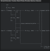
Components:
OpAmp1, OpAmp2: These are standard op-amps (e.g., TL072, NE5532, OPAx344 for low input bias current) used to create the precision rectification and selection.
D1, D2: Standard small signal diodes (e.g., 1N4148). These are crucial for the OR logic.
R1, R2, R3, R4: (R3, R4 missing in diagram but implied for input biasing/feedback if using different op-amp config) These are feedback resistors. In this common configuration, OpAmp1 and OpAmp2 are often configured with unity gain feedback around the diode.
R5, R6 (optional but common): Current limiting or mixing resistors before the final buffer.
OpAmp3 (Buffer): A third op-amp configured as a voltage follower (unity-gain buffer). This is essential to prevent loading the diode OR gate.
How it Works (Step-by-Step Explanation):
Let's assume we want to output the maximum of Input A and Input B, and both inputs are positive control voltages (which is typical after a precision rectifier).
Individual Op-Amp Branches (OpAmp1 & D1, OpAmp2 & D2):
Consider OpAmp1, Input A, and D1. This part of the circuit acts like a "precision voltage follower with a diode."
The op-amp will try to keep its inverting input (-) at the same voltage as its non-inverting input (+). So, it tries to make V(-) = Input A.
For current to flow through D1 to the Output_Combined_Pre_Buffer node, D1 must be forward-biased. This means the voltage at OpAmp1's output must be (Output_Combined_Pre_Buffer + V_forward_diode).
Page 1