Search Results
7/2/2025, 11:23:03 AM
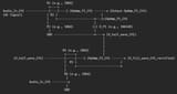
Part A: Precision Full-Wave Rectifier (PFWR) - Two Channels Identical
(e.g., for Channel 1. Channel 2 would be an identical circuit with "CH2" labels)
Explanation of PFWR (Part A):
OpAmp_P1_CH1 and D_P1: This is an inverting precision half-wave rectifier.
When Audio_In_CH1 is positive, OpAmp_P1_CH1 output goes negative, D_P1 is reverse-biased. No feedback through D_P1.
When Audio_In_CH1 is negative, OpAmp_P1_CH1 output goes positive, D_P1 is forward-biased, closing the feedback loop. V_half_wave_CH1 becomes positive and proportional to the negative half of Audio_In_CH1.
(Note: There are many PFWR topologies; this is one that demonstrates the two-stage idea.)
OpAmp_P2_CH1 (Summing Amplifier): This op-amp combines V_half_wave_CH1 with a scaled version of the original Audio_In_CH1.
By carefully choosing resistors (R4, R5, R6), this summing amplifier inverts the half-wave and adds it to the original signal such that the output V_full_wave_CH1_rectified is proportional to |Audio_In_CH1| (the absolute value).
The output of this summing amplifier (V_full_wave_CH1_rectified) is an active, low-impedance output that can source and sink current.
Page 1