IMG_5452
md5: 208f054bf8c21e3911b2486a26d6fbba
🔍
Previous thread:
>>2880131Here we discuss microcontrollers (MCUs), single board computers (SBCs), and their accessories, such as Atmel mega and tiny AVRs (Arduinos), PICs, ARM boards such as blue/black pill STM32, ESP8266/32s, RP2040, Raspberry Pi, and others.
For general electronics questions (power supplies, level shifting, motor driving, etc.) please ask /ohm/.
>where can I find verified quality microcontrollers and other electronic sensors or partsdigikey.com
mouser.com
arrow.com
newark.com
>but that's too expensivealiexpress.com (many parts here are fake, particularly specific parts out of stock in the above sites)
lcsc.com
>I need a part that does X and Y, with Z specifications. How can I find it?use DigiKey's or Octopart's parametric part search. Then purchase from one of the sellers listed above.
>how do I get started with microcontrollers, where should I start?There is no defined starting point, grab a book and start reading or buy an arduino off ebay/amazon and start messing around. There are a plethora of examples online to get started.
>resources:https://github.com/kitspace/awesome-electronics
>RISC-V microcontroller list:https://codeberg.org/20-100/Awesome_RISC-V/raw/branch/master/RISC-V_MCU_development_boards.pdf
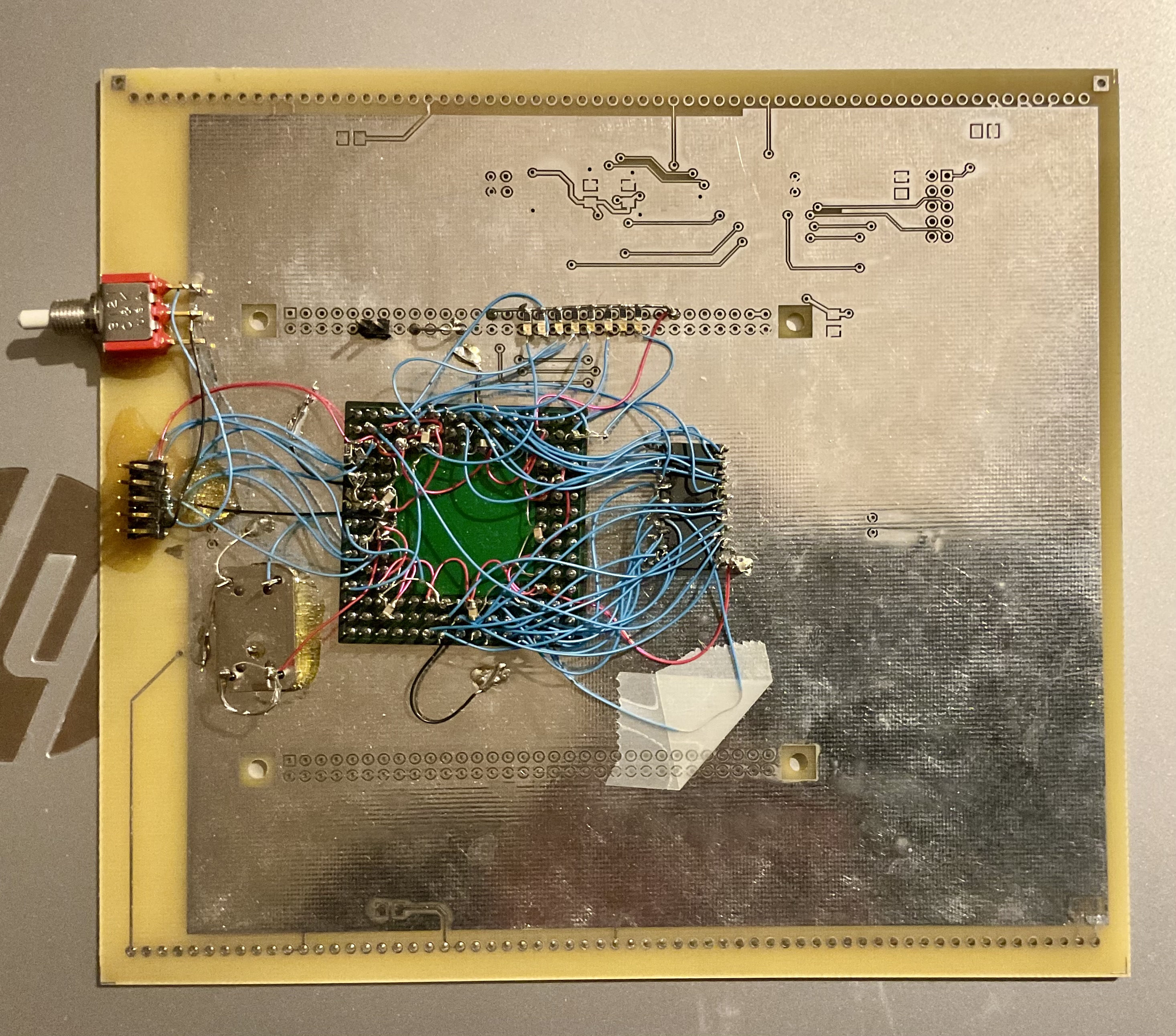
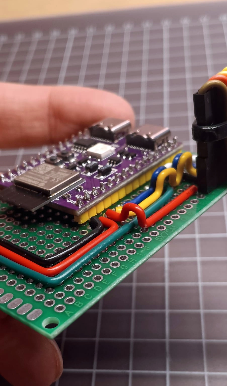
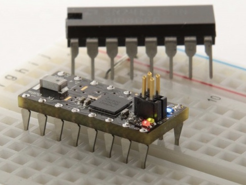
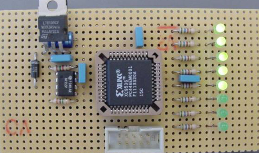
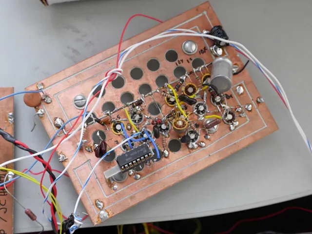
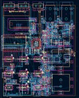
>>2909001 (OP)So you're telling me there's a person out there with the skills to etch or mill a custom PCB, and he just deadbugs a PGA atop it? Or is that board being reused?
>>2909006Looks like a re-use.
I do that all the time for come pcb carrier material, insulation, build-up standoffs, edge card connectors cut off and re-glued to something else.
I've even cut out the class AB discrete transistor audio amplifier out of the middle of a CRT TV circuit board and used that, as-is with all the components still on it. Why effort?
>>2909080>I've even cut out the class AB discrete transistor audio amplifier out of the middle of a CRT TV circuit board and used that, as-is with all the components still on itThat doesn't require deadbugging a 144-pin PGA. Assuming he made that PCB for a different project in the first place, it would probably be less time consuming to make the new board than to solder all those jumper wires.
>>2909001 (OP)Hello /mcg/. I'm going to be making my own CNC controller based on the STM32F4xx MCU using the Rust language and David Brown's zephyr-rustlang plugin for the Zephyr RTOS. Boardsd should come in next week for initial testing. Will be networking to all the serve drivers and front panel via EtherCAT and CanOpen, plus a Wi-Fi and normal Ethernet interface.
>>2909293> ethercatGood choice but how complex of a CNC is this going to be if you need 2 bus networks and rolling your own rtos stuff
Also what servo drives? Beckhoff?
>>2909310Lichuan servo drivers. I want the kinematics system to support 5 axis G code using Interpolated Position mode for the CIA402 interface of the servo drivers. The CL3-E57H driver. I may end up writing my own CAM frontend in Rust too if the FreeCAD CAM workbench just won't work.
>>2909293>rust>zephyrAbsolutely disgusting.
>>2909316Don't care, I like type safety. I will say the rustlang plugin is a little rough around the edges, but it does make firmware that compiles.
>>2909293>I'm going to be making my own CNC controllerFor what purpose? Are you planning on implementing a feature that existing CNC controllers do not support? Or is the memory safety of Rust the entire point? Do CNC controllers ever crash or have memory leaks?
>>2909293>zephyrPainful
>RustLess but also painful
How big of a masochist are you anon?
>>2909452Painful? What are you talking about? I type 'west build && west flash' and my dev board has firmware on it. I actually have a fairly frictionless dev process. Plus I have renode to do virtual emulation of my STM disco boards on.
>>2909346Yes, actually. I want all the interfacing for the servo drives, VFD, and front panel to be done through CanOpen/EtherCat, and I don't want an ESP32 MCU. I want an STM based mainboard with an F4xx or H7xx MCU. In addition, I want to integrate in a remote management and instrumentation subsystem, since I'm making this for my own factory. That way I can have a central machine management server which streams the progress of all running jobs back to a dashboard.
So, yes, I do want to do things no current CNC firmware on the market can do.
>>2909535> rust, like/need type safetyugh
> STMeuropean
> my own factoryno employees with a clipboard to go around the machines and write down cycle counts
> streams of datanobody will work for me so I'm going to burn my time micromanaging robots on my "single pane of glass" console.
>>2909532>Painful? What are you talking about?Anon any time you have to create a custom board and it's devicetree and have to define or whatever custom nodes, aliases etc etc.
It's pretty painful, i wouldn't recommend zephyr if you're doing something that doesn't require multiple proprietary network stacks. Or anything that requires real-time processing or fast interrupt response.
>>2909552lol you're not wrong
>>2909555>CanOpen>EtherCat>Reticulum>MeshtasticI actually do a lot of nonstandard networking stacks
>>2909555Oh, and regarding real-time response, end stop sensors to trigger interrupt code to brake all servo drives seems like a good use case, like there's tons of reasons to want an RTOS.
>>2909582>>2909583Zephyr really is perfect for you then, it was literally intended for plug and play applications where a lot of networking is involved.
>ThreadX has extensive safety certifications from Technischer Überwachungsverein (TÜV, English: Technical Inspection Association) and UL (formerly Underwriters Laboratories) and is Motor Industry Software Reliability Association MISRA C compliant.
Is this worth anything? What did they actually do to verify it? Personally, I find the code awful. It's overly verbose with lots of completely useless comments, repeats itself very often, has very large functions, is littered with ifdefs, and uses moronic Microsoft conventions like VOID and ULONG typedefs instead of using C types and intXX_t typedefs. I'm not impressed, although it does a lot of other things right that other RTOS don't get right, like not requiring dynamic memory allocation.
How good is AI with rust? What AI service can I use to write firmware in rust?
>>2909746Because Rust is so strict AI can usually cludge through any problem the borrow checker throws, and by the time you're done it will most likely be a fully working app. But without knowledge of proper patterns and Rust idiomatics, anything like low level firmware will have a painful amount of references and passing of ownership.
>>2909685I was under the impression that ifdefs were how you wrote multi-platform portable code if you don’t have a bloated HAL. But maybe I’ve been learning from the wrong sources (i.e. Marlin).
>>2910157ifdefs are something to avoid in clean code. Sometimes they are unavoidable, but most time they are not. Normally, you can rely on the compiler to optimize out code in "if(0)" blocks even at -O1. But it doesn't help that most devs don't seem to know C at all, and write code that happens to work at -O0 only.
>>2910157Rust solves conditional compilation with cargo features and enabling blocks of code via feature flags
>>2910195> depending on the optimizer on a microcontrolleryeah, no. I've seen optimizers get complicated ^= bit toggle expressions wrong.
> if(0)If I write that, my compiler better implement the conditional jump since i'm likely to patch the machine code to enable the block with a dynamic re-configuration if I want to.
More developers should be sent out into the field to fix problems in embedded systems controlling facilities that, if problems arise, could cause severe environmental catastrophes. They get a serial debug monitor, and an oscilloscope with a logic analyzer.
>>2910297>If I write that, my compiler better implement the conditional jump since i'm likely to patch the machine code to enable the block with a dynamic re-configuration if I want to.You don't know C.
>>2909582> networking "stacks"what a bunch of stupid names.
"Meshtastic" is trying to gain cred by stealing it from the original LANtastic from the 80s and 90s (and still in use today where nodes were sealed into walls and the controllers are running DOS)
Like those dorks that buy used CRTs to play retro games thinking they look like OGs rather than kiddies.
>>2910289How is that any different to ifdef?
>>2910354> cargo different from ifdefIt’s cargo… car, go. Get it?
It’s a pakled reference from star trek.
“He makes things go. He is smart”
Without car go, how work? No work… it won’t go.

file
md5: 7115676a65b59507859537e5b95679f5
🔍
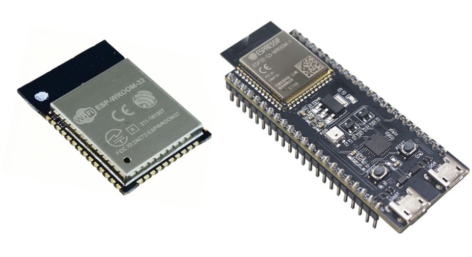
I got an ESP32, do we have any list of small challenges/projects so I can learn using all its capabilities?
>>2910625You are literally a guy that has a solution and no problem.
>>2910300C isn't machine code
What they described just sounds like asm
>>2910625>I got an ESP32the module or a dev board?
I haven't seen a project/challenge list for microprocessors.
i bought a uart usb debugger thinking it would connect to an ads1115. now i've learnt everything comunicates using different protocols. i'm going to stick to i2c for development probably for life now unless you convince me otherwise.
>>2911820If you got an FT232H those can communicate multiple protocols, I2C included.
Welcome back
I hate microcontrollers now
>>2909108Manhattan and dead bug construction is generally vastly underrated, but I'd draw the line there too, especially today. Note though that the board that's on is not solder masked, which I'd guess puts it back to when you'd save real money that way, 10-20 years maybe? And we don't know what's on the other side, but there's no fanout from a top side footprint for the BGA chip. So I think it does point to reuse at a point in time that it would have been more expensive or even time-consuming to just order a new board.
>>2912618I guess I can see myself doing that if the PCB came wrong and I had a 24 hour deadline, all the while questioning my life choices.
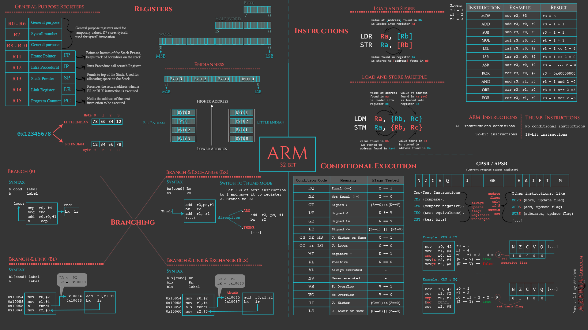
>a simple arithmetic instruction can be used to change processor mode, like returning from interrupt mode to normal mode
What were they thinking?
>>2909582I use etherCAT at my day job, and I think it is the industrial protocol meant to rule over all others. Smart choice.
I've converted all of my meshtastic nodes to rnodes. Reticulum is the most interesting cryptography project I've encountered, I just wish he'd rewrite it in something besides python
>>2909293Based and retard pilled. I'm working on a generic motion controller platform myself but instead using a normal fucking computer so I don't kms. How are you planning on doing the HMI part? Also been thinking of why not putting a display on EtherCAT but I haven't thought of a decent protocol to use, like you can copy CoE/FSoE state machine idea and exchange events that way but also why not use literally anything else if you aren't actually taking advantage of PDOs?
>>2913083>cryptographyNobody's been tapping your ethernet and examining traffic in promiscuous mode in, like, 25 years now.
There's been virtually no actual decryption based attacks in that time. high-end cryptography is largely a scam at this point unless you're the military, but they're just using signal apparently. lol.
>>2913134>Nobody's been tapping your ethernet and examining traffic in promiscuous mode in, like, 25 years now.>There's been virtually no actual decryption based attacks in that time. high-end cryptography is largely a scam at this point unless you're the military, but they're just using signal apparently. lol.
>>2913083What’s the advantage of rnodes over meshtastic? Any hardware differences at all, or is it all in the firmware? If I recall meshtastic isn’t meant to jump through gateways (e.g. transmitter >{lora}> gateway >{internet}> gateway >{lora}> receiver), likely because it would require dynamically updating routing tables or lots of extraneous traffic. But being able to use it for long-range comms with internet connected gateways for where there isn’t a continual nodal path would be really nice.
Also what’s the 2.4GHz protocol like?
>>2913134Well yeah, all the important traffic can be assumed to be encrypted to the point it’s not worth trying to decode. Do not tear down your fences after observing wolves haven’t killed your sheep since you put the fences up.
>>2913228rnode message routing is cleaner, meshtastic nodes rebroadcast everything they hear. this creates throughput issues on large networks due to wasteful repeats.
a reticulum network does not require a routing(?) node, but you could benefit from having one online all of the time because it will hold on to unsent messages until the intended recipient is rediscovered on the network.
I hardly know anything about reticulum, but it is incredible and the companion apps are pretty nice, too. Nomad network is comfy af
>>2913238Ah, so it can route packets without clogging the network with redundant retransmissions. Neat.
I'm a dumbfuck when it comes to microcontrollers. Got a teensy and some parts because project idea. Any idea whre I can simulate that crap (circuit, maybe with code aswell) before building? I don't want to toast my teensy ...
I have a dump of the flash storage of an ESP32 chip I want to reverse engineer.
Is there any explanation somewhere on what the default flash layout works? I don't think the binary starts at address 0 of the flash chip, so I'm trying to figure out what parts I'm supposed to load. Where's the entrypoint?
>>2913831I found this https://github.com/tenable/esp32_image_parser
Seems to work on the flash dump, I was worried for a second it'd have an internal flash I needed to dump.
>>2913831>official, detailed docs>most of the firmware, even the ROM bootloader open source>the format is somewhat obvious anyway>still has to ask on 4chanAnd I thought I was bad at reverse engineering.
>>2913866I ask 4chan because maybe I could get a quick answer.
I'm not familiar with ESP32 at all and started looking into it today, I don't consider the flash partition format to be super obvious (there's unrelated data at 0x1000 so I expected it was a flat binary with fixed offsets) though I can see now it's rather simple. I couldn't find a linker script that makes sense, esp-idf seems to generate it during build, and I couldn't be bothered with setting up the toolchain to see what it generates.
Managed to find the technical reference manual, finally, but I had to dig for a link to it in a different PDF.
I can't find documentation on the format of the "storage" partition, I hear it could be SPIFFS? I'm also seeing a lot of symbols as strings in the binary, but I wonder if I can parse and map them to function offsets.
>>2913877https://github.com/dynacylabs/ghidra-esp32-flash-loader
This thing is a godsent. Parses all the symbols properly.
>>2913877> microcontroller> linkerlol, what is the world coming to
>>2913951nigga I'm talking about the linker that makes a flat binary, unless you're writing assembly for PIC or some shit anything C will have one.
>>2913791LTSpice is decent for circuit simulation, but it can’t do code, at least not easily. I believe CircuitJS is the same in this regard. With a programmable voltage source you may be able to do some simulated microcontroller fuckery, but generally I’d say you shouldn’t need it. Anything that could possibly damage the microcontroller should be taken care of independently of what the microcontroller is trying to do. If you’re unsure, then add a series resistor and some protection diodes. Once it’s safe, then you can mess about with the code IRL. Maybe use a cheaper MCU for initial testing.
If you’re making an MCU-controlled SMPS, my condolences.
Is there an actual difference in the silicon between the RP2350A and RP2350B?
Curious if I can still read/write to the extra GPIO pins as normal in the A variant, even if they aren't broken out in the package.
>>2913997what? ... are you going to de-encapsulate it, get some tiny gold wires, take some pentazemin, a microscope, and weld extra leads onto the die?
>>2914015Nothing that extreme. There's a software trick I want to use that requires unused pins, wondering if they're available for that. Previously used it on the RP2040, hoping to port it to the new chip.
>>2914031NTA but I guess you can still access the pins in firmware if that's what you're asking, but what use is that if they're not broken out on the package?
>>2914083I need the extra 8 bytes of storage.
Just can't quite fit it in the allotted 520 KiB that it comes with.
>>2914083>what use is that if they're not broken out on the packageThey can be used to send bits between PIO state machines while leaving the FIFOs and other mechanisms free
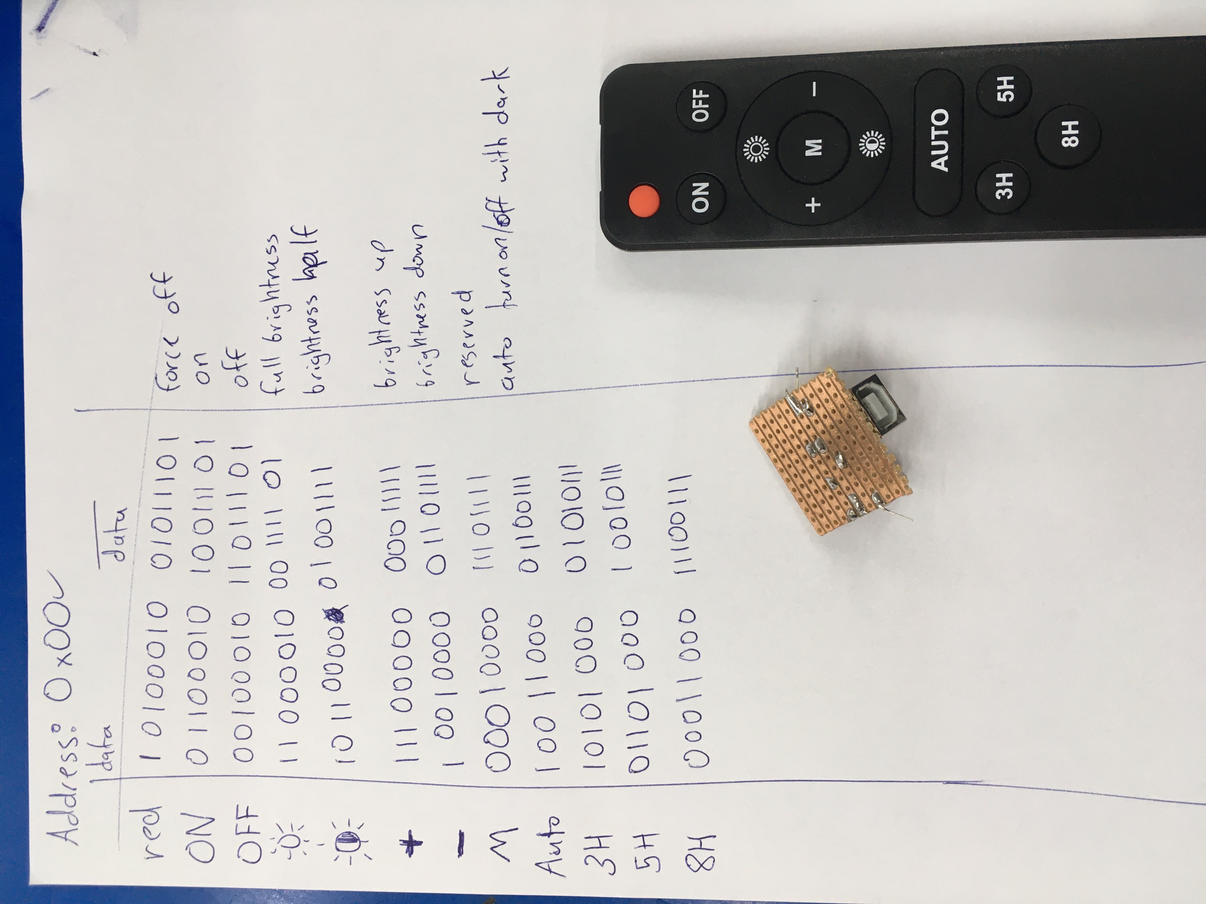
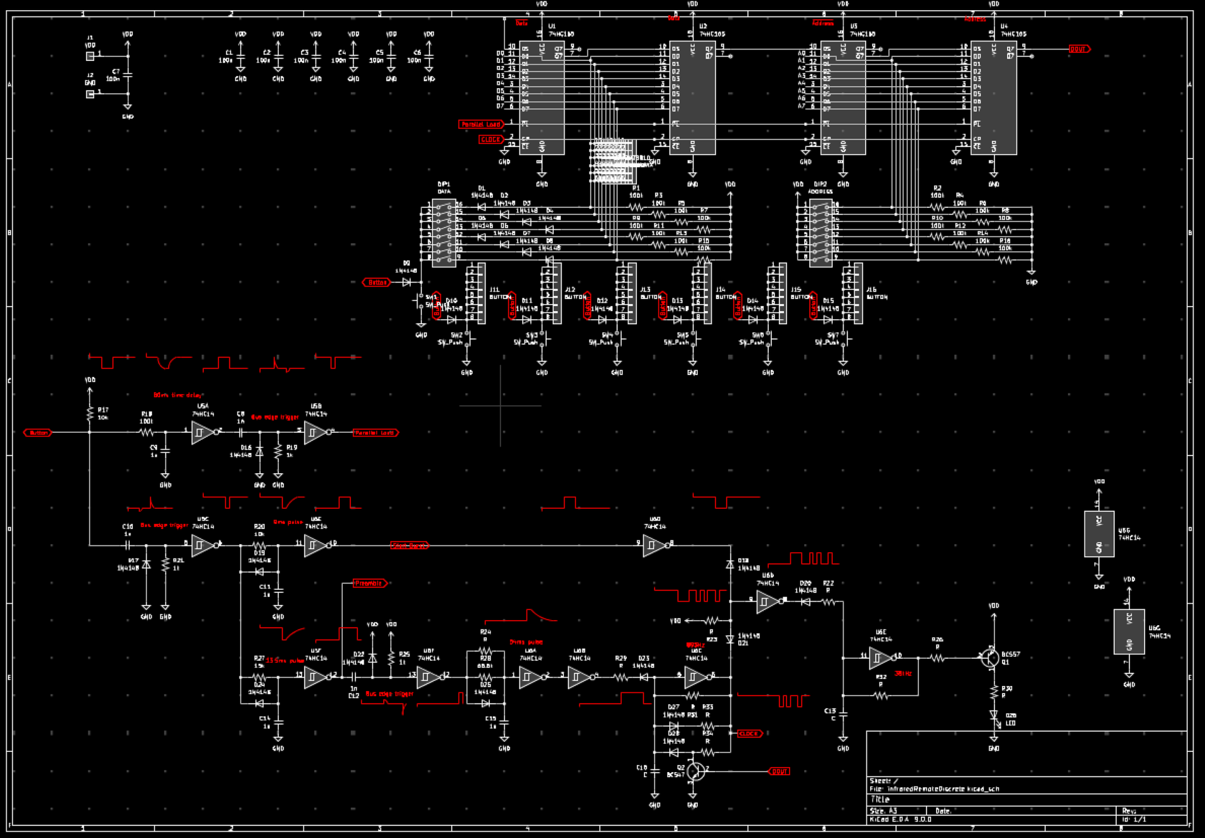
>want to clone an infrared remote control out of a product we sell at work
>decide the best way is to use an infrared receiver wired up to an arduino that saves it to eeprom, should be really easy to bodge some shitty code together in a few hours, just read out the memory once i'm home
>turns out infrared signals can be like 300 bit widths long
>i'd need at least two samples per bit width to be able to recreate the signal, so over 600 bits = 75 bytes of storage per signal
>probably going to run out of eeprom
>guess i'll have to use an sd card shield
>turns out infrared signals are varied and come in a few different protocols with different bit widths
>guess i'll have to use this fancy IRremote library
>library is complicated and looks to have lots of pitfalls, requiring debugging via serial
>somehow can't get serial upload working in new computer, despite usbasp working fine
>try esp32 instead, same problem
>realise i won't have any debug feedback once at work to tell me if i'm measuring the thing properly once there
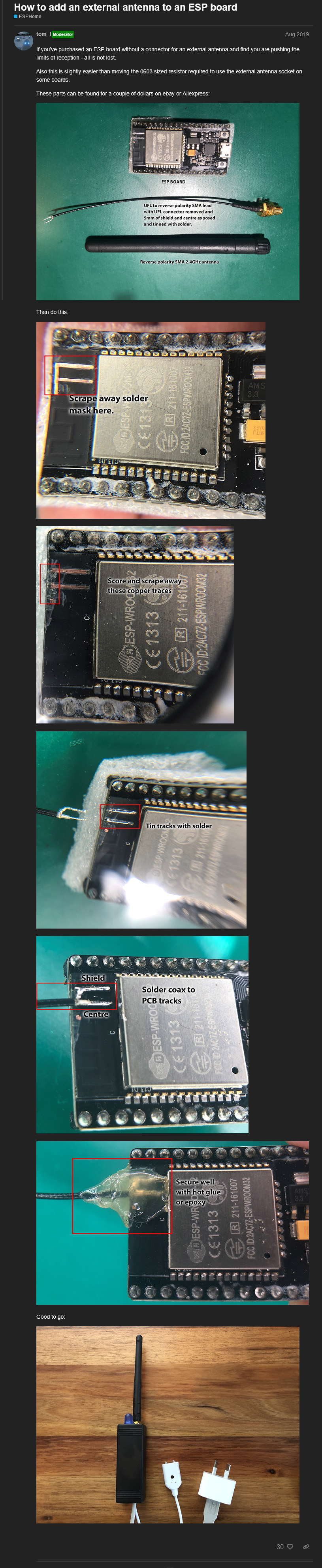
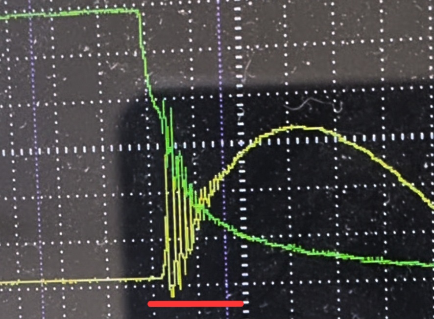
screw company policy and professionalism, i'm taking one home at the end of the day and reading it with my oscilloscope at home
or maybe unboxing and using an oscilloscope at work
alogs.space fell for the beagle blue meme
imagine an arm chip for this never mind the fact that its not enough anyways
>>2915319beaglebone blue*
>>2915305>and reading it with my oscilloscope at homeHa. That's what I was going to suggest while I was reading all that, except that I was hoping your workplace would be decent enough to already have one.
Yeah, if you only need to emulate one protocol, it's easier to do it yourself rather than dragging in heug libraries.
Hopefully the protocol won't suck in other ways like a weird modulation frequency. (which is probably not a problem if you write your own custom code for it anyhow)
One more thing: who cares how many bit widths there are, it's only transitions that matter, just store a list of timer values between transitions. That's what most IR dumps are anyhow. Now if there's 300 transitions in a signal, holy fuck that's awful.
>>2915374>I was hoping your workplace would be decent enough to already have oneThe scopes we sell are bottom-end rebadged hanteks or whatever, which are still better for digital shit than my CRT DSO. Hoping I can just transcribe a couple of button presses to get the key info of address and data, then just copy the data part for the rest of the buttons. I'll convert the high and low signals to actual data manually afterwards, assuming the scope doesn't have a built-in decoder for it.
>if you only need to emulate one protocol, it's easier to do it yourself rather than dragging in heug librariesYeah I'll just implement it on an ATtiny13 with delay() bullshit, screw the library. Can't get rid of these damn chips.
>>2915376The common method is "Hi Lo" for 0 and "Hi Lo Lo" for 1 if I recall. So it's 2 or 3 bit-widths per bit, but I don't feel like trying to write microcontroller code to interpret that, since it means adapting for an unknown baud rate, and it might not even be that protocol. Hence the idea to record the raw output of the IR receiver.
That said, putting the library example code with the LCD and beeper in an enclosure might be a nice thing to have around.
>>2915376>>2915486Actual time values between transitions is going to be no better to store than just sampling 1s and 0s at two samples per bit width. Instead of 00110011000011000011 I'd be storing 2,2,2,2,4,2,4,2, or 010010010010100010100010, which is even longer. I could compress it more by ignoring the on times, but for the manchester encoded IR signals on times are important too.
>>2915305Just replace the LED with a speaker, record it on your cassette deck. And to play it back, replace the speaker with a LED.
>>2915488Unfortunately my cassette deck doesn't record sounds up at 38kHz. But that is a very fun idea.
>>2915487If the format is not known, the standard way of representing an arbitrary IR code is a list of milliseconds between off and on edges. This is useful for recording unknown codes for later decoding, you don't even need a scope, just have it dump the pulse and gap lengths over a serial port. They can be played back from that data without knowing the format.
Once you know the format, you can use custom code to generate the pulses from just the code word. Then you have a short binary number along with an enum of the format. It's still best to make it build a list of pulse lengths on playback. That makes the output code a lot simpler, especially if you are supporting more than one code format. Then all your format generators output the same format, with only one hardware driver to send them.
And I just spent half an hour trying to find the old remote code files that are formatted that way. There used to be archives of those for old PDA remote apps. Now everything on Google has been poisoned into "how to use your consoomer remote".
Also, don't be a retard by talking about having trouble with old tech, then acting like someone who bothers to reply couldn't possibly know anything about it.
>>2915492>a list of millisecondsIf I were doing that on the microcontroller, that would mean doing some sort of decimal multiplication or bit-shift befuddlery to convert the period of the MCU's clock/timers into milliseconds. Definitely taking up more room on the SD card so EEPROM would be right out. Even if I had access to a serial port to stream it to instead of storing it, I'd probably prefer to do the processing on the computer instead of the MCU. If I had access to a computer that could do that at all, I'd just use my nanoDLA that I just remembered I own, since PulseView can probably decode the IR signal directly. I'll try reading the scope and writing out the 1s and 0s on paper, and attempt to process them with python or whatever. If that fails I'll be able to take one home and back again without having to worry about stock levels later next week, and use the logic analyser there.
>There used to be archives of those for old PDA remote appsThe world seems to be moving away from infrared remotes, and also away from open APIs and computer accessible data stores. We're moving towards smart devices using proprietary protocols and 1st party web services that get discontinued within 5 years. They change the terms of the sale after the sale.
>Also, don't be a retard by talking about having trouble with old techI don't understand.
>>2915488This. Using audio equipment to record arbitrary signals isn't even a new idea.
>>2915520>convert the period of the MCU's clock/timers into millisecondsWhy can't you decide the tick period at compile time?
>>2909001 (OP)I have to design a circuit to take readings from 16 load cells.
I'm using arduino nano with 16 hx711s so each load cell is connected directly to an amp,
Can I use a mux like CD74HC4067 to switch between HX711s data pins? clock pin is shared among all of hx711s
In software I'd use one scale from hx711 library and cycle through each module. setting each one's offset and calibration before taking each reading.
Would this work or am I being retarded?
I don't have time to reorder boards if I fuck anything up so I want to be at least somewhat confident before ordering
>>2915619Yeah, that should work.
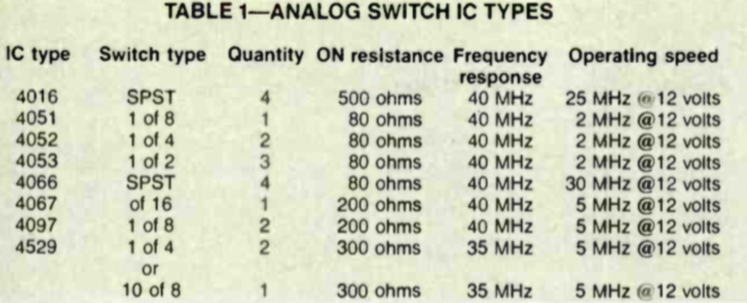
There’s a guy in /ohm/ that autizes over analog switches
>>2915656I am glad to be remembered. I’ll bust out the spreadsheet once I get home.
>>2915656>>2915703ok thanks I had another idea of using one hx711 and two 4067s to switch A+ and A- between load cells but I guess the resistance of the multiplexers would impact the accuracy of the readings
could that work with a mux that has 2 inputs?
>>2915707There are MUX chips like that, but you’d have to check crosstalk and bias voltage and stuff like that to see if it would influence your measurements, and also if it would be something you could compensate for. I’d investigate both methods at least.
IR codes in the wrong orientation:
>>2915305>want to clone an infrared remote control logitech makes a wide range of learning remotes
i have about 10 of them from the thrift store for around $6 each
it's even possible that someone else has already scanned the codes, so you just have to download them using the logitech app
the Apple TV remote can also clone codes, but it has very few buttons
havent checked but i'm pretty sure phone/tablet apps exist that can also clone codes if your phone has an IR receiver
>>2915802>the Apple TV remote can also clone codesHuh, I do have one of those. But I'd prefer a standalone remote control. I mainly just need on and off after all, so I can make it compact and run on a pair of AAs.
>>2915305can't you just read the spec sheet for the chip in the remote to see what protocols to expect?
and did you try using a flipper zero? not sure of the limitations of them but one of their main features is ir signal cloning and storage
I got that free tv that have damaged matrix ribbon wiring. Touching it removes vertical gliches but only partially. As far as I understand that ribbon is hardwired into matrix so I cannot raplace it and whole matrix is for trash, right?
If so I'm planning heating said ribbon with hairdryer so maybe it will repair itself by contraction
>>2915829>>the Apple TV remote can also clone codes>Huh, I do have one of thoseactually, i'm wrong about that
it's the Apple TV itself that can learn codes so you can use a remote other than the Apple one
>>2915871>spec sheet for the chip in the remote to see what protocols to expectDidn't look, but those are usually just blob-on-board chips. I imagine it was custom programmed, considering the chip that receives these signals inside the solar lamp is just a microcontroller.
>flipper zeroExpensive and would take a while to get here. Doing this:
>>2915754 took 30 minutes once I figured out the format.
>>2915879>>2915880It might be repairable if you can A: find which line is damaged and B: use good magnification, workholding, and rework tools to add a jumper wire across the break. Not easy, nor worth a professional's time unless it's a pretty good TV, but it's already fucked so I'd consider spending some time on it. Or leaving it damaged and just using it as a status monitor where dead pixels doesn't really matter.
>>2915802Harmony remotes suck (for me at least) because of their operation design. They expect you to be using one TV screen and changing it between multiple different inputs.
Also, check the ones you find in thrift stores, any of them that used rechargeable batteries, the batteries have probably bulged and can't be removed. (the ones that use AA batteries, the usual "it's leaked all over" applies instead)
They also one of the few things that depended on Microsoft Silver(b)light for their setup programming. In case you don't remember, that was Microsoft's attempt to remake Flash in their own image.
>>2916050> harmony remotes suckI concur.
Yeah, I don’t think their whole scenario that they were “solving” was ever that realistic, especiall nowadays.
Mine has the black rubbery coating that exuded this sticky white gel, and it’s fucking gross to touch.
Looks like they ticked every planned obsolescence box.
Wonder what processor it uses… might be interesting to try and hack them to do something usable.
>>2916003> using it as a status monitorHah! I just got a TV out of a dumpster, tested it and the top 25% is all fuckulated.
So I was thinking about hooking it up to a rasberry pi and using it as clock and/or status monitor by putting it a picture frame type thing that blocks out the bad top area. With that, it looks like a 16:9 aspect ratio.
>>2916055>black rubbery coatingYou can do something about it with Goo Gone and a lot of work, but whoever came up with that shit is an idiot. All it did was add to the pile of e-waste when people throw out crap where the rubberization has turned to goo.
>>2916058You might even be able to set that manual letterboxing in the TV's own firmware. Probably not, but maybe.
>>2916055>> harmony remotes suck>I concur.agreed, but what's a better alternative?
no one else has the range of devices, the apps, and the library of 500,000 device codes you can download
for people who buy second-hand stuff --- which never come with remotes --- Harmony is a god-send
>>2916119Where I work we have One For All brand. Never heard of Harmony.
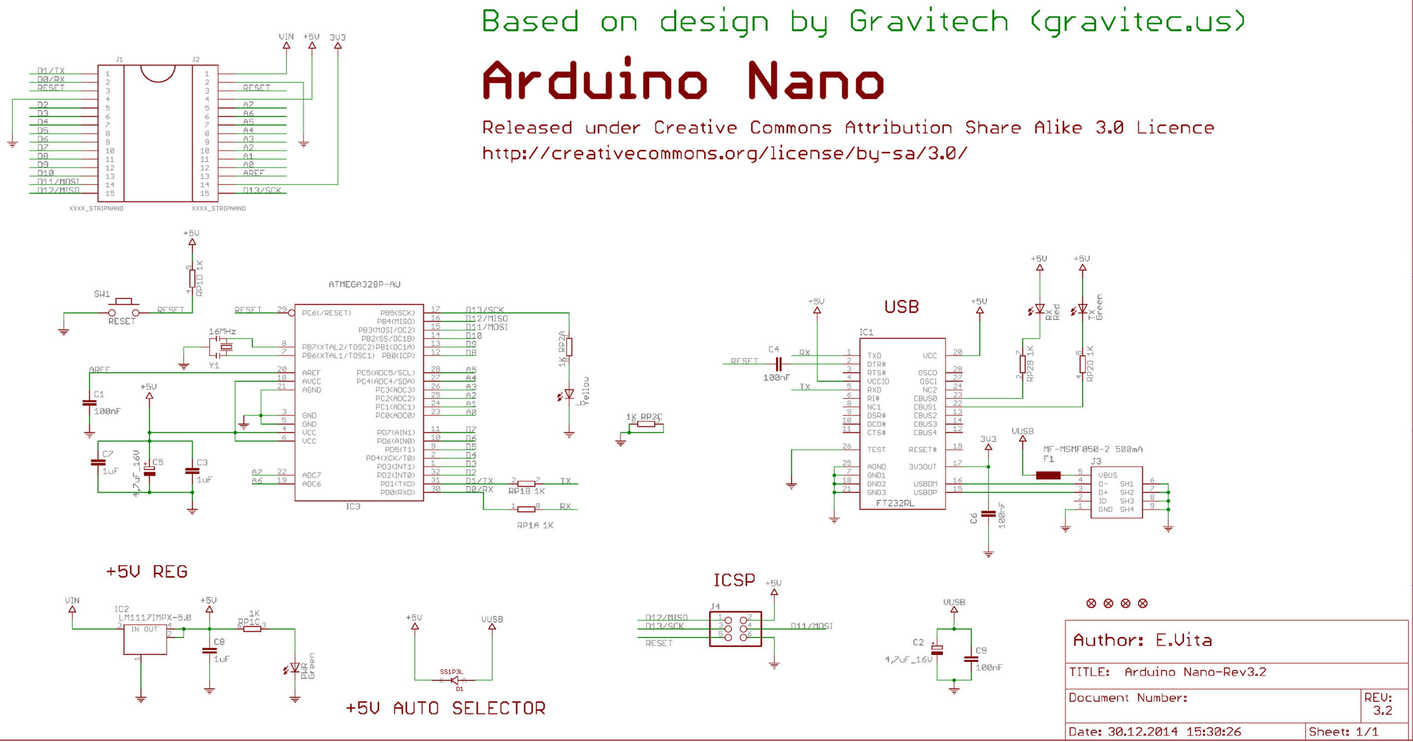
is there any issue with using the vin pin on an arduino as a 20V voltage source for a motor?
file
md5: b71b6c9329f07882e4ae645589299a39
🔍
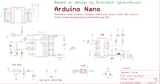
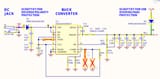
>>2918037Well for starters the Vin pin on an arduino is an input to the arduino, it doesn't output any power. Also it's connected to a voltage regulator (AMS1117-5.0) with a 15V absolute maximum input rating, FYI voltage regulators are directional devices. See the schematic, pic related is for a nano but all common arduinos are pretty similar.
If you want to power a motor and Arduino at the same time, you have a few options:
>run the motor and arduino off 5V>run the motor off a 7-15V source and feed that voltage into the arduino to power it>run the motor off some voltage greater than 5V, and use an external step-down converter to power the arduino, while respecting the maximum input voltage of the converter>run the arduino off a 5V source and use an external step-up converter to power the motorThe latter is not recommended, as common 5V sources can't provide more than 2.5-15W or so, and a 20V motor probably wants more than that. Motors are fine to undervolt and even overvolt within reason, just know that both the motor's no-load speed and stall-torque will scale with voltage.
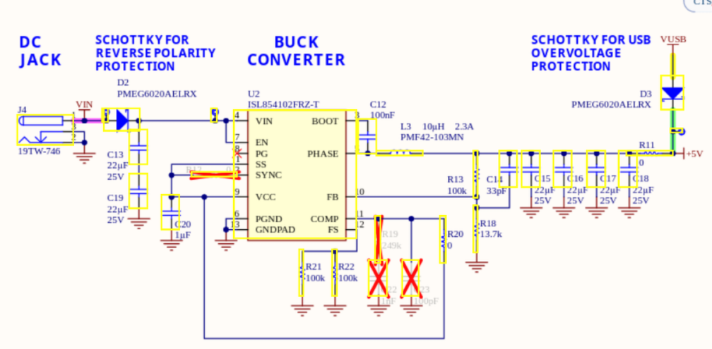
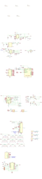
>>2918250>Vin pin on an arduino is an input to the arduinothe assumption i'm making is that it's connected to the same copper plate as the barrel jack. Also the and the uno r4 buck converter goes up to 24V.
file
md5: 5d02b2d2f0c2cf35b72a6315a73aff91
🔍
>>2918254>the assumption i'm making is that it's connected to the same copper plate as the barrel jackYeah it is, both the Vin pin and the barrel jack positive pin are right before a diode. Pic related is from the R4 Minima schematic. The Vin pin is still an input, the buck converter cannot work in reverse to turn 5V into 20V.
Does atmega shit have any real advantage over more modern chips?
>>2918303If the 32bit ISAs aren’t too complicated for you, there’s very little reason not to go for more modern chips. These are typically more expensive, but the CH32V series are cheaper and better for basically any application.
But you should also be asking yourself the opposite question. For a given application, does using a new MCU family have any advantage over the MCU family I’m already familiar with? That you already have a toolchain for?
Anons, serious question. I fucked up and quit a controls engineering job, but the ops manager ended up retiring and now theres a jeet there in his position. I know the owner and he's somewhat of a friend of the family so the job security is definitely there despite having to deal with a few stupid jeets. Its been a year or so and I'm thinking of asking for the job back. Should I do it or take a job in broadcast engineering instead? I'm growing tired of the tech rat race.
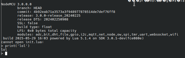
So if want to program a nodemcu v3 with lua i first flash the firmware and then just put lua files on there?
I can use the arduino IDE but it uses another language and im trying to figure out the workflow with lua. Some programs people use have been abandoned 10 years ago.
>>2920368> been abandoned 10 years ago.You’re falling into the “newer is always better” fallicy. Nowadays, it’s almost never better.
I don’t know where this love of shit like lua comes from, might as well find (or make) a native port of a 6502, 8080, or z80 BASIC that fits in 8 kB and go with that.
Even better if you don’t need fp (i.e. integer basic)
>>2920447>You’re falling into the “newer is always better” fallicy. Nowadays, it’s almost never better.I use programs that were made 40 years ago like X11 so i know that old stuff still works but it could be that some part of flashing got revised like the USB standard was a billion times so im worried when old software has to keep up with new hardware.
>I don’t know where this love of shit like lua comes fromIts small, simple, fast, and i already have experience using it so why not? On the desktop realm using its JIT compiler gets you faster speeds than many compiled languages even. And it does this while using very little memory.
>>2920447>I don’t know where this love of shit like lua comes from,>BASICLua is 32 years old and infinitely superior to garbage like BASIC.

file
md5: f4711354a7fff11d49719dc5580c4c69
🔍
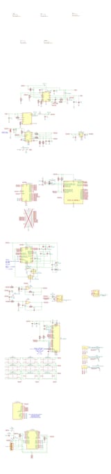
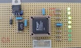
Ladies and gentlemen, we have liftoff.
>>2920497Nice!
Where’s your free memory statistic?
>>2920485> Lua is superior to BASICI’ve written tons of lua. It practically *is* BASIC.
There’s a reason lua didn’t get out of brasil for 20 years. It’s not that great.
> luajitOkay, but that is due to the jit ‘engine’ being great.
You might as well go with something like the parallax propeller, and do something with those old 14" vga monitors you have lying around.
>Reposting from /dpt/, as I wasn't aware of this general.
Learning how embedded works and very confused with security.
I made an ESP32 cam connect to home WiFi and send images via a websocket to my Debian VPS's Nginx reverse proxy, which then routes the image stream to a dockerized backend (stores the image in shared volume).
Dockerized frontend displays the "video" stream via said shared volume.
Although the frontend has SSL and is behind an Nginx access list, the endpoint to receive the websocket image stream is HTTP.
- Is this insecure? The camera connects via home WiFi. If so, should I add Let's Encrypt SSL to the receiving endpoint and connect through WSS? (I tried, and the stream became very unstable, I assume because of the overhead or my trash code)
- if I use RTSP or MQTT, I will still need to encrypt traffic? Am not sure what is the best practise, and can't really find any good examples.
Help appreciated. I really don't want chinks watching.
>>2920507>Where’s your free memory statistic?Don't know how to do more than flashing firmware, reading/writing files and reading all serial output with screen.
The screenshot shows a terminal open via screen.
Anyways im following a tutorial i found on hackaday. Might have sped up things a bit if i used it from the start.
>>2920508why are you so worried about security? who cares... do you realize people were using unencrypted video baby monitors for decades? And still are!
I've got lots of my live video out there on the open internet, if they want the pictures it's their problem not mine.
If everyone put all their pictures up, unencrypted and free access, there would be so much shit out there that it would drown out everything. It's the encrypted stuff they're going to be going after.
If you want to be really horrified, listen to this:
we used to have this thing called a "telephone book" which, like, doxxed everyone in the entire city with a phone! crazy eh?
>>2920508>>2920533Also, crypto is going to be using up, like 90% of the cpu resources; so it's basically a scam and always has been.
> inb4 "but there's hardware encryption on the chip, it's free"no, it's not. They're only "helper" functions. It still btfo of it.
>>2920533>why are you so worried about security?Primarily learning purposes and curiosity, secondarily because I give a fuck about my right to privacy, especially if I'm going to put up a camera in my appartment.
>Who cares...I do. You're free to have that opinion. My opinion is that this kind of logic fueled the surveilance capitalism machine's growth, in which we live in today. In my eyes, the usual "I have nothing to hide" argument is a cynical rationalization of the current state of affairs when it comes to privacy today. But I digress...
While I appreciate you making an argument, I don't see any of the questions answered (at least in a theoretical sense).
>>2920535> crypto is going to be using up, like 90% of the cpu resourcesThis is worth considering, but I'm curious if there's a way around this. Someone must've implemented this kind of thing already.
for my weather station. I thought doing cable management is gonna calm me down but I was angry and on the edge until it was finished. How do I get more relaxed?
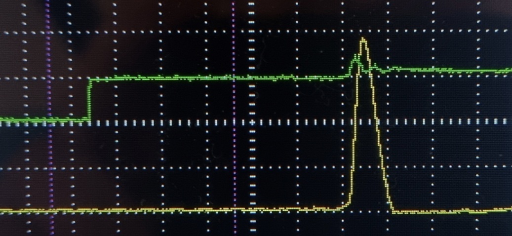
>>2920547i hope you aren't using that antenna or you're about to be more agitated
>>2920535>Also, crypto is going to be using up, like 90% of the cpu resourcesProper HTTPS also requires TLS certificates (which need to be stored and updated) and a working clock. What a load of bullshit.
>>2920508Instead you should probably just put a firewall in your router to stop your ESP32 being visible from outside your local network, then set up a VPS on your local network that you securely connect to instead.
t. have no idea what i'm talking about, but i heard angry man rossmann talking about doing that for home security cameras
>>2920579It will be fine, not like a bunch of unconnected copper polygons will act like a ground plane. But reception towards the back side of that board will probably be substantially worse.
>>2920546Isn’t wifi already encrypted?
I decided to challenge myself to develop games for microcontrollers so i can learn to make clean, efficient software and not the bloated shit that outsourced indians code these days.
here's a list of boards im thinking of purchasing.
>STM32 Blackpill
>Raspberry Pi Pico W
>LPCXPRESSO LPC802
>RTK7RLG240C00000BJ (RL78)
>MSP-EXP430FR6989
>EFM8BB1LCK (8051)
I already have arduino uno, pic18 and esp32.
What other boards should I get, im tying to kee it cheaper.
>>2921296I think it'd make much more sense to get started with some games before getting even more boards, you already have 3, just make some small stuff for those and then you can look once you mastered those.
>>2921300good idea
yeah i have plenty of boards i guess, i have arduino uno, pic18, esp32, i forgot to mention i got something called psoc 5lp which i've been learning recently. but evetually i would buy an stm32, pi pico, 8051 and ti mcu since they're kind of popular
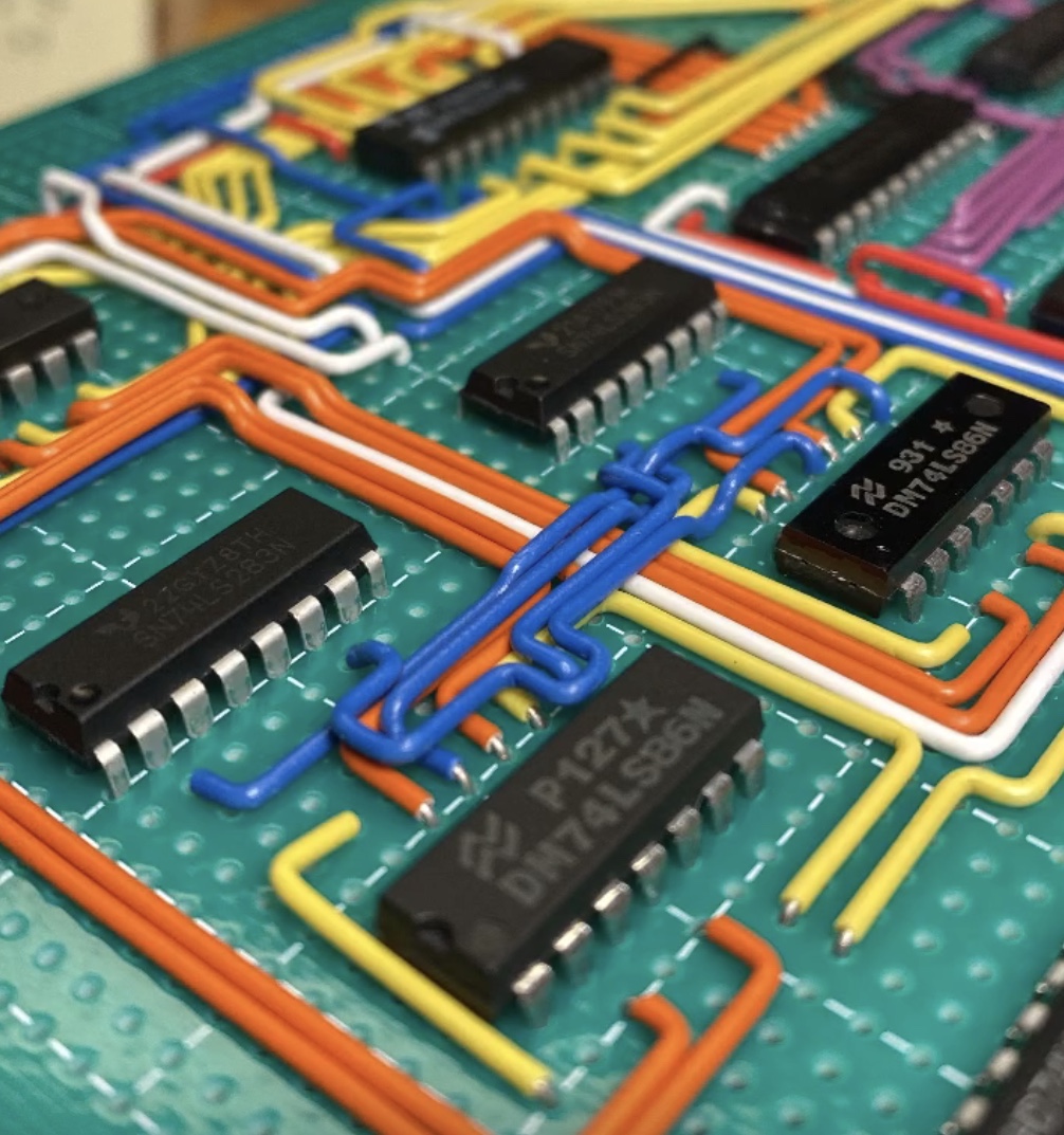
>>2920656thanks and yours looks stunning! What kind of PCB are you using and what tools do you use for planning your wiring?
>>2921296Unironically just make a game for the GBA. It's ARM, like most of your micros, and you can program it with just a datasheet (GBATEK) and without any SDK, or very minimal libraries (gbadev.net). It also has a serial port supporting quasi-SPI and UART, as well as bitbang/GPIO modes, and a plethora of emulators for the thing.
The only thing you'll be missing is dealing with uploading pictures over SPI to the slowest LCD displays imaginable. The GBA has good 2d hardware, although you can also render everything in software through the bitmap mode.
Sup guys
I decided to try to build an mp3 player
I've never designed anything before and the schematic I drew up is a creatura
can anyone give me a feedback on the design? I feel somewhat lost...
if you wanna join the project i can publish the thing on github
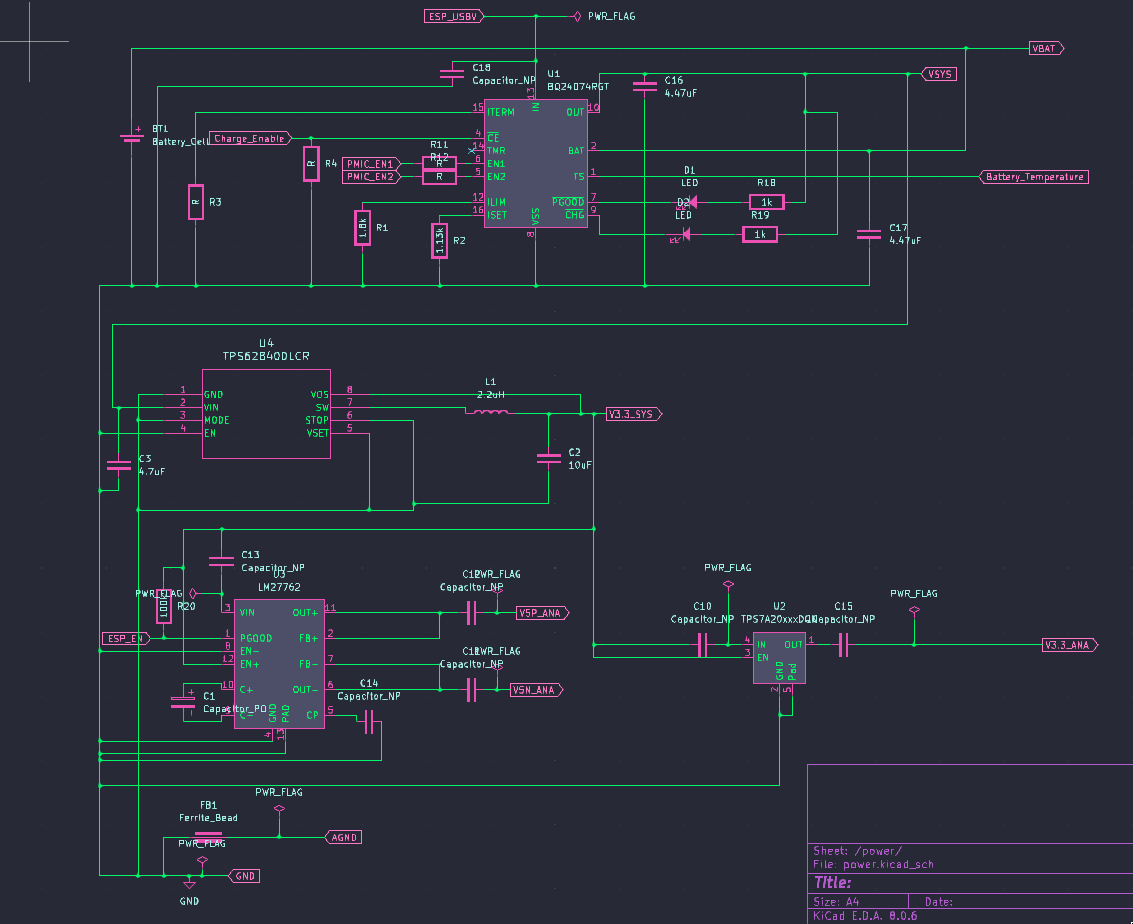
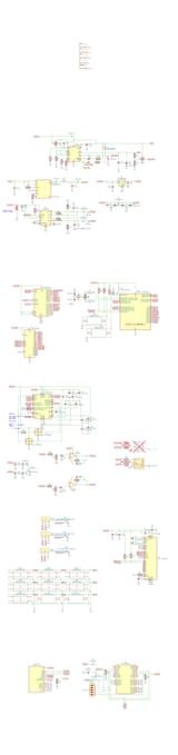
here is the power sheet

mammamia
md5: 2b3132896be0a87e172416ebf859e593
🔍
here is the mcu part

audio
md5: d7cfcadeddb61f5d9abc41318577562f
🔍
the audio

codio
md5: 6f7dedd9fb5637af61bafe013b25af5f
🔍
the IO
>>2921511Why not use a microcontroller with a d/a converter (the vast majority) built in?
Even 8051 cores run at 50 MHz @ 1 instruction/cycle.
>>2921543because I want to try to make something hi-fi
would sound better and would be an opportunity for me to learn more
the schematics I posted look kinda like shit
I've changed them a lot, I guess soon I'll publish them on github or something
>>2921511What's up with the series caps on the LDO U2? No LDO is going to be able to turn 3.3V into 3.3V filtered, if that's what you're trying to do.
Presumably this is meant to be portable, in which case make a list of all quiescent currents to figure out what's eating your power the most, both in standby and in use. It's best to figure out what parts you want to keep or not before you finalise your schematic and start working on board layouts. Of course, a design that you can prototype without ordering PCBs each time is valuable too.
I see you're producing a negative rail for your op-amps (also with series output caps for some strange reason), consider the noise and quiescent current implications of this compared to using a simpler single-supply design.
>>2921512>>2921514Why not use a button matrix instead of one I/O pin for each button?
>>2921513If you have an AGND and GND as separate rails, why is your DAC all running on AGND even to pin 27? Also I'd add inline control compatibility for TRRS jacks, or at least consider the two types of TRRS pinouts. Also RCA outputs.
Consider a dedicated headphone amplifier IC, it might make edge cases like extremely low/high impedence headphones easier to handle without fault. At the moment, C19 and C20 may have too high impedances for low-impedance earphones at low frequencies, causing bass rolloff, it's possible that some amp ICs can compensate for that. If you're using a bipolar op-amp supply anyhow, you shouldn't need an output cap at all. I recommend looking at some existing schematics to see how real products handle their audio interfaces.
>>2921543>Why not use a microcontroller with a d/a converter (the vast majority) built in?Most MCUs have an ADC, but most do not have a DAC. Also MCU DACs are pretty shit quality, especially compared to a nice TI I2S delta-sigma converter.
>>2921665> but most do not have a DACQuite right, I got that reversed. The reason is because generally you don’t need DAC if you have gpio and some resistors. A “ladder” of resistors, if you will. And, the more gpio and resistors you use, the less of a filter you need.
> my mp3 files are sampled at 8 kHz
>>2921730If you want a decent resolution (e.g. 12 bits) your resistor ladder needs to be unreasonably precise (e.g. 0.25% resistors), plus you get a bunch of bit-transition noise, and even the nonlinearity of your GPIO pins will start to influence things. It's just not a reasonable solution, even if you decide to buy a few hundred resistors and hand-bin them. Delta-sigma ADCs are the standard in audio reproduction for a reason.
For the kind of low-resolution DAC stuff a non-audio MCU might want to do, like sending a value to an SMPS tracking input, or a linear LED dimmer circuit, or what have you, you'd typically just filter your PWM instead of bothering with a resistor ladder.
>>2921738> .25% I *make* them precise by going low then add some nichrome wire rather than having my kids spend hours binning them. You need crazy values sometimes anyway.
> low res, DAC stuff a non-audio MCU might want to do, like sending a value to an SMPSSounds like, here, you’re saying even 1 bit would do. Did some research and…
Check out picrel! Looks like 1-bit DACs are actually better quality than your old multi-bit DAC idea!
Eye opener for me. Anyway, yeah, so all you need is 1 GPIO pin, and no ladder network snd you should be all set.
output2
md5: be592d0591f7b7e23e30fc4f38304a1d
🔍
>>2921665>LDO is going to be able to turn 3.3V into 3.3V filteredyeah right, those caps were very retarded
>Presumably this is meant to be portable,exactly
>make a list of all quiescent currents to figure out what's eating your power the mostis there an easy way to do this? Like software simulation or something?
>consider the noise and quiescent current implications of this compared to using a simpler single-supply design.right. to be honest i kinda jumped on the first thing i found that was good enough, OPA1622 seems to have some pretty solid specs
regarding noise, thd etc: do you calculate these things with pen and paper?
>Why not use a button matrix instead of one I/O pin for each button?that would be great, I need GPIOs
since the buttons are 9 < 2^4 ... is it feasible to encode them into 4 or 5 wires instead of 6?
may be a retarded solution idk
>why is your DAC all running on AGND even to pin 27?true, that's bad.. now i have fixed it
>it might make edge cases like extremely low/high impedence headphones easier to handle without fault.damn things seems harder than i thought
>>2921665thanks a lot for the feedback!
i hope the image is readable, i thought it may be rejected by 4chan if it was too large
>>2921833sup anons, i'm back
so i made some changes
do you think it's reasonable to use mosfets to handle some PMIC logic, instead of wiring stuff to the ESP?
the mosfet on the PMIC is actually wrong in this pic..
ENC1 should be high when in standby and low when charging, i'll fix this later
what do you think about the demultiplexer i marked as dnp? is it okay to connect it to the MCP (GPIO expander)?
it would save a lot of GPIOs, also i'm not a fan of matrices lol
I placed a 32.768 MHz oscillator for the ESP, it may come handy..
though I don't know whether it's better to have an IC oscillator or a crystal and other components.. why would one choose something over another?
I updated the PCM, i read the datasheets more carefully
there i put also two oscillators.. for covering the whole sampling frequencies
a PCM register will need to be configured to enable them at the right time.. I didn't investigate much
the OPA1622 is still as before
i think i am done with the display circuitry
i need to finish the SD and the USB stuff
PS picrel is now bigger
>>2921892i am not really sure about the ferrite beads, what do you think?
>>2921800I think a 1-bit-DAC might be a delta-sigma? I know delta-sigma modulators have a “1-bit ADC” in them. Doing delta-sigma (or class-D-style PWM) to make an audio signal digitally is kinda infeasible, needing hundreds of MHz for your PWM clock to get past just 12 bit depth. There’s a reason delta-sigma DACs and class-D amps use analogue oscillators.
>>2921833>is there an easy way to do this? Like software simulation or something?Just go through the datasheets reading their quiescent current values.
>regarding noise, thd etc: do you calculate these things with pen and paper?Also just check the datasheet, though you may need to interpolate values or graphs (e.g. it has 2.5V spec and a 5V spec but no 3.3V spec), or even look at supplemental documents like application notes. Any relevant documents should be linked to from the datasheet itself, or from the manufacturer’s webpage for the part.
For power rail ripple specifically, you’ll want to look at the output ripple specs of that split-rail inverter chip, then check the power supply ripple rejection specs of the amplifier circuit, and see how many dBV you get left. Then compare that dBV value to your bit-depth. If you’re controlling output signal volume by telling the DAC to output at a lower amplitude or to use an internal PGA stage, then turning your volume down won’t also turn down your power supply noise at the amp chip. Definitely breadboard or otherwise prototype the output section and listen for noise on your most sensitive IEMs.
>the buttons are 9 < 2^4No clue what this means, but yeah 9 buttons generally needs 6 GPIO pins. You could get away with 4 GPIOs if you charlieplex them with diodes in series with each button, or just 1 GPIO if you use a resistor ladder. Lmao.
Also last time I tried to use one of those PCM chips it needed a strange clock frequency, so make sure that you can divide your main clock properly to get that somehow.
>>2921893Check the ferrite operating frequency.
Does anyone around here use M2M modules? I'm just looking for something that will let me send an SMS from sensor to receiver circuit but I'm completely lost on what I should be looking for.
done
md5: 64575053f8a1e2a976638baa2b971451
🔍
hi guys
I'm done with the schematic.. i'm somewhat confident it turned out good
any comment is appreciated
now i'm going to do the PCB, any tips?
i was thinking of doing something multilayer but idk how many layers i need.. 4? 6?
guess i'll start with 4 kek
oh anyways the schematic is here: github com/hydrastro/owo
>>2922233i need to choose
in the power sheet:
- the PMOS and the NMOS, Q1 and Q2
- R-ITERM, regulating the termination current threshold of the battery charging
- TH1, the thermistor... idk
- R3
in the io sheet:
- the display R IREF "reference current source" ... idk somewhere between 510k and 910k
in the storage sheet:
- the D3 diode
regarding the capacitors n other shit: i have no idea...
apart from one or two electrolytics the others would all be ceramic.. but I don't know of which size
i think i'll go either for 0805 or for 0603s
since designing stuff on pc is kinda annoying i don't think i'll work on a breadboard with through hole stuff but rather i'll go directly for the PCB hoping it will work
i guess i'll find out.. i never used kicad nor designed anything lmao
>>2922256i managed to get most of the footprints of the components and tidy them up
do you think I should add a line out jack? i don't know how i could add it and whether it would mess up the audio circuit
i have some pins left on my expander so i can place other fun stuff
i realized the whole thing can be used as an expensive gameboy lol
or an expensive walkie talkie?
Hi,
I want to connect this chip: https://www2.mouser.com/ProductDetail/Microchip-Technology/RNG90-SSVDA-T?qs=9vOqFld9vZVk6wBjQG9AIA%3D%3D
to my Raspberry Pico. My question is: Do I absolutely need extra resistors and capacitors as stated here (in the diagram): https://www2.mouser.com/new/microchip/microchip-rng90-cryptoauthentication/
or can I connect directly via i2c to my pico? If I need two extra resistors and a capacitor how would I know exactly the type that I need?
(I'm a programmer, not hardware designer)
Can somebody explain (who understands)
Can I use 2x 4.7kΩ and 1x 0.1µF?
I would also buy a few components to make sure I have everything here. What are must-buys?
>>2922296> Do I absolutely need extra resistors and capacitors as stated here datasheet says it depends on what you're connecting to
if the CPU already has pull-up resistors, you dont need to add external ones
otherwise you might
cant hurt if you add them anyway
4.7K seems reasonable
>What are must-buys?impossible to predict what your future needs will be
so just buy big kits of every value
>>2922233Add testpoints fucking everywhere if you're not going to breadboard it first. And extra passive component spots where might be necessary.
I typically just do 2 layers because it's piss cheap, you can often get away with just having different ground planes in different parts of the board, with generous ground via stitching on either side of traces. But 4 layers does give you more freedom to keep your planes uninterrupted.
dudes
ive got a bunch of RP2350B and trying to compile a code that asks for arm_math.h, so went to get the CMSIS library. version 4 includes this file but doesnt support the core (CM33), version 5 def supoorts the core but doesnt have that file and if i try to load it as zip into arduino IDE it tells me the file has no library in it? wtf? what do i do here. also from the earle philhower definitions what board do i use, didnt find the 2350B in the list, so im using "generic 2350", and it works but whats the proper one?
>>2922343>if the CPU already has pull-up resistors, you dont need to add external onesSome people say to add them because the built in one is 50-80k while something like 20k is recommended. But with one or two sht31d's I had no problem with just the built in.
>>2922363>Add testpoints fucking everywhere yeah i will definitely do
>And extra passive component spots where might be necessary.you mean like adding empty pads for hypothetical extra passives?
sounds weird
>>2922343Thank you so much :)
eh
md5: 369b85511ce63143c7b8d6ad7ae8f9dc
🔍
>>2922412update:
i've added three slide switches, very cool stuff
and
i tried to place down the UI
i'd like to make the thing as small as possible
the buttons grid is 9x9cm
the display is 29x14mm
the rotary encoders are way bigger than i thought and I wasn't able to find any better
the big rectangle is 53x47mm
i have some GPIOs left so i may aswell add another row of 3 buttons
since the UI is taking up so much space i think I'll have to place many components in the back
or in the upper part.. what do you think?
the critical things are: the usb trace pairs, the audio signals and some other things.. probably the display signals
so i need to think carefully where to place: the audio jack, the usb port and the sd card slot
if it's feasible i'd like to have all of them at the bottom.. do you think it's feasible?
so my questions are:
how big should i make the pcb? how close to the edge can i place the rotary shits?
would you place another row of buttons?
if i want to add another jack as line out jack.. can i just split the traces coming out of the dac and connect them to a jack, through a 10 ohm series resistor?
What should i use to turn a 3.7 v rated battery into 5 volts to power an esp32 or two batteries.
>>2922592>What get a dollar store power bank, pull out the lil circuit inside
the full-size USB connector is the 5V output, the micro USB is 5V battery charger
https://www.youtube.com/shorts/3BO97Jvm5-o
>>2922473SW4 is a bit higher than SW5 and SW6.
>>2922375To set the "2350B" variant, just select the "Generic RP2350" as your board and then in the Tools -> Chip Variant menu select "RP2530B".
To get arm_math.h, you can download the "Arduino_CMSIS-DSP" library in your Arduino IDE's library manager. It will compile the math functions from source just fine.
layout
md5: 9da8ec9e3f87665bb176898c4273831a
🔍
>>2922620thanks
i've changed almost all connectors and also the rotary encoders because they didn't fit well
now they all fit, but i need some feedback
is it okay to make the audio jack protrude a bit?
hmm maybe the jacks are too short
btw everything is on guthib
pic related
>>2922682okay i've somehow managed to place all the ICs
how? by feeling
i placed the audio stuff near the jacks, between the jacks and the esp
then the other things where there was space
i still haven't traced any line though
should i place the RLCs now or start tracing lines?
should I go for 4+ layers? my idea was to have two ground planes but it would be better to separate them with a power plane, right?
i don't know what shape should they be and if they have to overlay each other perfectly or not at all
so many things, but so far i made some progress
i should not forget to place some holes for the case lol
i don't know if i'll keep the peace i had, the next few weeks i'll be pretty busy with the university so whatever
layout2
md5: dac957a30a46d621447043c4c7251cd2
🔍
forgot pic
I have a very simple arduino project. It has two push buttons, two potentiometers, two RGB LEDs, and a speaker. The idea is one potentiometer selects the color for the LEDs and one push button turns them on; the other potentiometer selects the pitch of the tone and the other push button makes the speaker make noise. When I tested these out individually, they worked fine. When I try to combine the two projects into one, only the LEDs work and the speaker stays silent. Does anyone know how to fix this?
>>2922696https://pastebin.com/n04QaWCC
>>2922696If the individual code components worked and the merged code doesn't - and you didn't make a mistake with the merging, it's probably because some command is blocking the triggering of the other. For example if you check for a variable in a loop, and then play a sound, that sound may block the checking on a single thread. That's my guess anyways.
The keyword you want to look into are "interrupts" and if you want to learn more of the why, look into the basics of CPU scheduling.
>>2922722Well you can review my code here:
>>2922718Let me know what stands out. Right now my best guess is after the first if-else statement that controls the first potentiometer and button I start another just like it but for the speaker and I wonder if that would be fixed by changing the second if-else to just be part of the first
>>2922696>I have a very simple arduino project.>line 620: }else if(percent2 > 32 && percent2 < 34){
if(BUTTON_PRESSED2){
tone(BUZZER_PIN, NOTE_FS3);
}else{
noTone(BUZZER_PIN);
}
}else if(percent2 > 33 && percent2 < 35){
if(BUTTON_PRESSED2){
tone(BUZZER_PIN, NOTE_G3);
}else{
noTone(BUZZER_PIN);
}
(this goes on for every value 1 to 100)
this is pretty fucking bad dude sorry. like really fucking bad.
find some equation to convert a percentage value into a note value and you can get rid of about 500 lines (replaced with one line)
e.g. if(button_pressed) {tone(pin, percent2 *2 + 30) } else {noTone(pin);}
you check the percentage and then test the button press. you test the button press 100 times, every single time the test is the same. imagine if you wanted to change how it worked, you would change all 100 instances?
the reason it doesn't work is the same reason that i think you will struggle to find help with it, and the same thing i'm complaining about above. writing code you need to break a problem down into logical steps which you can implement. this code isn't simple it's thousands of lines which actually makes it difficult to read because of all the dead unnecessary code you have to scroll past to find any issues at which time you have forgotten what you were looking at earlier.
also i have no idea if its you or pastebin but the indentation is all over the place, its impossible to read or know where you are in the clauses for any line. i pity anyone who seriously tries to debug this even though as you say (despite how lengthy it is) it is fundamentally a simple program.
>>2922729You don’t need to test it 100 times, you just hold down the button and twist the knob of the potentiometer. Also, I figured it out and the solution was as nonsensical as my code: the if-else statement for the speaker needs to be declared before the one for the LEDs
>>2922592Why can't your Esp32 run with 3V7?
>>2922725>Let me know what stands out.Sorry anon I was asleep (timezones and such).
Seems like you found the issue?
>Also, I figured it out and the solution was as nonsensical as my code: the if-else statement for the speaker needs to be declared before the one for the LEDsI had a quick look over your code, and the reason is almost probably what I mentioned. I didn't try to figure it out exactly, because 1000 lines are a bit much for your functionality.
Assuming my guess with scheduling is right, here's a basic explanation:
When you program for a single processor computer and it has only one thread (a lot of microcontrollers) you have to think of it as a machine that can only do one thing. However, usually they have modules that you can think of as helper robots, that they can delegate to. When you tell the robot to play a sound, it will go to one such helper robot, tell it to play the sound, and then be ready to do the next thing. This takes one or a few clock frequency pulses. If however you tell it to [code] delay(n) [/code], then the robot has to sit there and manually count the time. During that time it can't do anything else, meaning it can't check the other commands you want it to check, essentially "breaking" or "freezing" the entire program for a bit.
A more elegant solution is to use a function such as millis() https://docs.arduino.cc/language-reference/en/functions/time/millis/ to get the time since startup and then check if that time has elapsed - that way the robot will note down the current time, be free to go on with his day, and when he gets here again he can check if the time has passed. If the program is small, that will work just fine.
If you want him to exactly do it at the right time, there's a concept called interrupts. Basically an interrupt is a helper robot that can take the robot that's currently doing its one thing, tell it to stop and force it to look at its project, before the robot goes back to where it was and resumes.
>>2922725>>2922786Lastly some advice on improving your code, not from a functionality perspective but a code structure perspective, feel free to disregard, but I'd recommend you try to understand the concepts because they will save you time in making it as well.
Essentially anytime you re-use code, that is you copy paste some part of code, you should ask yourself "can I just reuse some function or method to do the repeated part?", because most of the time you can. The usual candidates to do so are: functions/methods, modulo, a math formula.
In your case you are defining the notes from octave 1 to octave 8, but we know that the frequency distances in hz between those notes are identical, so it would make more sense to write a function that takes the note name and then calculates the frequency by using (baseNoteFrequency + octaveFrequency * Octave). That turns 90 lines into maybe 20.
The big if-else statement mapping the percent to functions, reuses a lot of functionality. Ask yourself: Can I automate/reuse some functionality to split the 100% into usable chunks?
A trick to do so is to (ab)use how integers are handled in C. If you call (percent/8) you would get a decimal number (that is a number with a . somewhere), but if you write that code into a variable that holds integers (int) it will cut off anything behind the dot. So for your first if-else statement you'd get 0, for the next 1 and so on.
(cont)
>>2922725(cont from
>>2922790 )
Now you can simply write this code:
int colorArray[13][3] = [[0,0,255],[128,0,255],...] //Array containing your color values
int section = percent/8
if (section !=12){
if(BUTTON_PRESSED){
pxl.setPixelColor(PXL1[0], pxl.Color(colorArray[section][0], colorArray[section][1], colorArray[section][2]));
pxl.show();
px2.setPixelColor(PXL2[0], pxl.Color(colorArray[section][0], colorArray[section][1], colorArray[section][2]));
px2.show();
}
else{
pxl.setPixelColor(PXL1[0], pxl.Color(0, 0, 0));
pxl.show();
pxl2.setPixelColor(PXL2[0], pxl2.Color(0, 0, 0));
pxl2.show();
}
}
else{
if(BUTTON_PRESSED){
rainbow(4);
}
}
This function reduces 245 lines into 20, and it's still not optimized in terms of readability, but this should point you in the right direction for where to improve. Hardcoding the colors is also usually a bad choice, instead you can probably write some basic logic code that'll do that for you from one value.
You can do a similar method as this division into chunks in the code example to reduce your other big if-else statement.
>>2922718>that repetition with checking percent2Just give up, get claude, and vibe-code it.
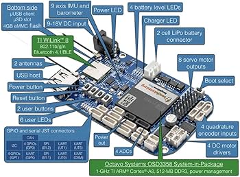
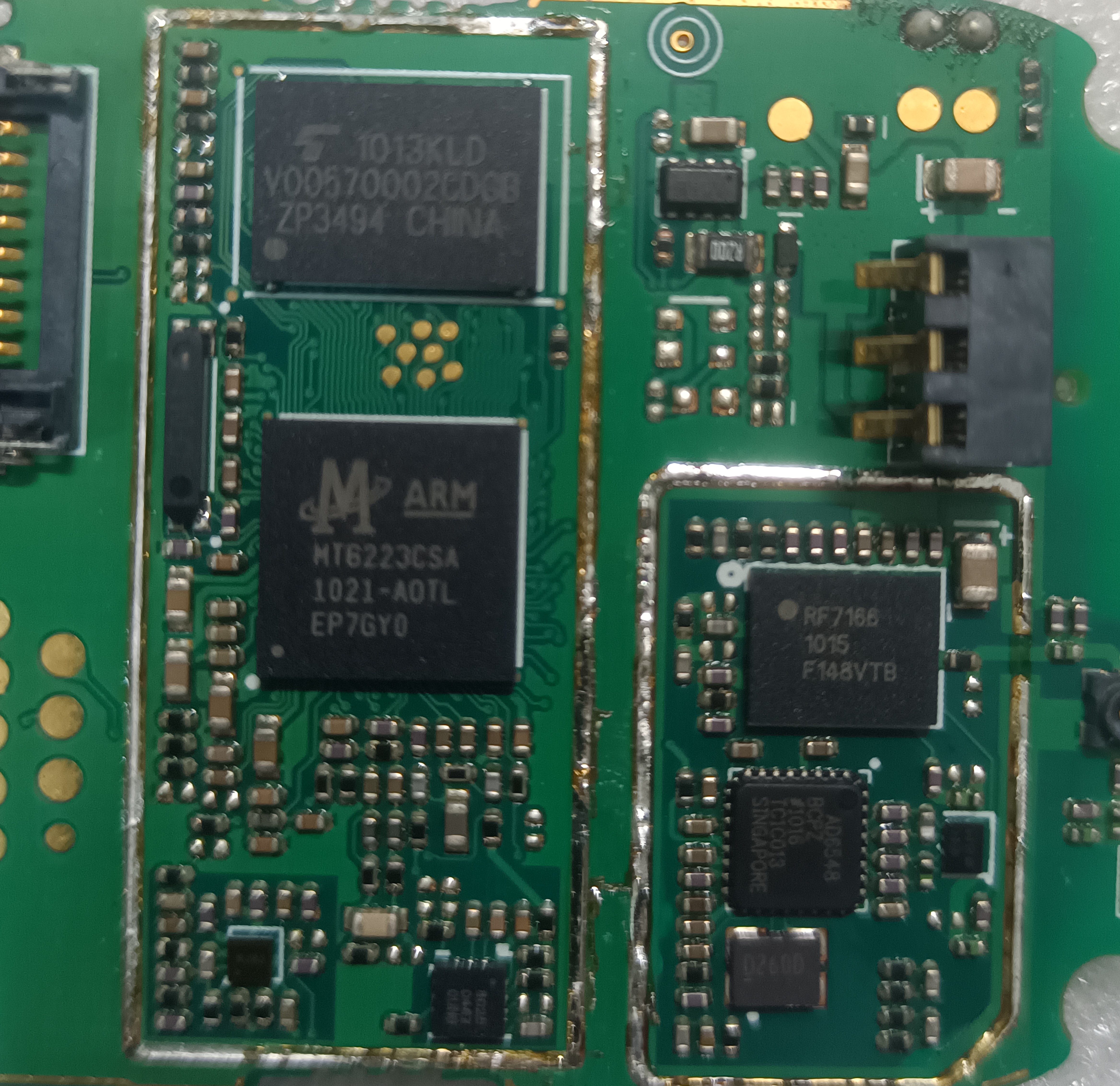
Any idea on how to read ROM on this phone?
>>2922819You mean the Toshiba TV0057002CDGB 4Mbyte SRAM + 16 MByte NOR Flash chip there above the Mediatek MT6223 chip?
I guess you could google the datasheet, desolder the 81 pin BGA package chip, put it onto a new PCB adapter / breakout board and then connect it to a PC3000 or XGecu T76 and read out the NOR. The datasheet tells you about all power, data, address and control signals for the NOR.
Or, if you're able gain code execution on the processor, dump the memory directly and write to an SD card.
Want to share my frustration.
Building a device that has rp3250 and esp8266 and the talk in spi. Ordered a prototype with both on jlcpcb, worked flawlessly.
Primary reason I chose both is there around $1 each and that matters when you order 1000 of them.
Esp, however SUCKS ASS. I gets the job done, but it's spi is half duplex with 64 bytes max per transaction. For reasons I had to go with spi slave for it, so I got this fucking
- hey I want to talk interrupt line
> what's up, what's the status
- <status>
> request concerning status
respond
Monstrosity that kind of has master in slave arrangement.
Fuck esp8266, but at the same time, $1 is $1.
>>2922592Instead use an HT7333 or similar ultra-low-dropout regulator to step down the 4.2Vmax power to 3.3V, or even 3.0V, instead of using the ESP’s existing low-ish dropout regulator. Better quiescent current compared to a switching converter. Though if you’re doing 5V USB stuff, you will want to step up to 5V instead.
>>2922729And here I thought my 15 nested if-statements back in uni was bad.
>>2922910Do you need the ESP for wireless reasons? What bit-rate do you need? Using UART, or USRT/synchronous-serial (totally not the same thing as SPI I promise) might mean less overhead around your comms transactions if it can keep up.
>>2922906Wow, you know the number? I tried googling v00570002cdgb to no luck. How did you know that there's supposed to be a 't' suffix there?
sure I'll do some ball pad to thin wire soldering
>>2922819>>2922906Is this a old dumbphone?
If that flash chip is only 16mbyte then it's not going to have a lot of things stored in it
What are your intentions once you have a dump of the rom?
>>2922926> Do you need the ESP for wireless reasons? Yes, wifi.
> What bit-rate do you need? Using UART, or USRT/synchronous-serial (totally not the same thing as SPI I promise) might mean less overhead around your comms transactions if it can keep up.I am aiming for 100kb/sec so at least 2mhz to compensate for shitty freertos "you can't yield for less than 1 tick, which at least can be 1ms"
What sucks is with freertos when you sent your message, next one will only likely be sent on next tick, because I HAVE to use freertos because of wifi stack running on it, so you do your 64 bytes burst and then you have to wait for a millisecond to process a reply, you can't just hog waiting in busyloop because wifi will die.
Uart seemed unrealistic at these speeds anyway.
layout3
md5: 37c5947eb4d450f1ebb648ab886be2eb
🔍
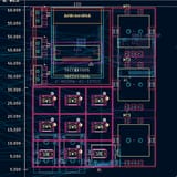
>>2922690managed to place most of the components, they're all very close to each other but I want the board to be small
i am considering changing the packaging of some chips, especially that shit SOIC-24 mux/demux taking up too much space
i am kinda worried though that I may not be able to route stuff around.. what do you think?
at this point i am considering also going with many layers
>>2923027> Uart seemed unrealistic at these speeds anywayHave you considered multiple channels/multiplexing?
>>2923027Doesn't the RP2350 have multiple cores for this kind of reason? Or does the RTOS not allow for that?
>>2923148It has a risc-v core for buzzword/fad compliance, and generally people might want to eff around with it reasons.
>>2923113There is no way you'll be able to route that with less than 4 layers, possibly 6.
>>2923113Print/draw it on paper and cut it out, to see if it's too small.
>>2923154It has two ARM cores and two Risc-V cores, you can only use two cores at once either way.
>>2923173You could do it in 2. Would be messy, but definitely doable. Vertical traces on one layer, horizontal traces on the other. No ground plane.
>>2923148> Doesn't the RP2350 have multiple cores for this kind of reason? Or does the RTOS not allow for that?RP3250 is awesome. The bottleneck is in dogshit ESP8266, shits slow and stupid but cheap.
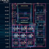
>>2923113I managed to place everything
it's super packed
i also started drawing the ground and power planes:
ground planes are brown, the small one is GNDA
the power planes: the two horizontal are for +-5V for the OPA1662
the one around them is the 3V analog
and the bigger one is the 3V digital
i can't route stuff on the surface, i think i have to route in new layer(s)
i need some feedback ;-;
i forgot the picture, again
>>2923178>Print/draw it on paper and cut it out, to see if it's too small.i did it, it's 65mm x 4.5mm, I like this size
>>2923173>There is no way you'll be able to route that with less than 4 layers, possibly 6.yeah I noticed
i was thinking of doing:
top layer: IO stuff
1 copper: power
2 copper: ground
bottom: signals
apparently bottom is so packed i can't route shit there
the audio part is the most sensitive and i'm worried that it may become noisy if i route it on the other side
so now idk what to do.. i mean where to do the routing
for digital stuff i could do it on the other side because i don't care
for the analog.. should it between the OPAs and the ground plane? should i place yet another ground plane
btw is it good or bad to "embed" a power plane into another like i did?
the source of the two analog planes is the LM27762, which is those three orange circles on the right: is it too far?
>>2923300okay i've been reading some references
i thought having split ground planes for GND and GNDA was a good idea...
well it is but apparently it's also damn hard to properly design it
i would need a lot of stitching capacitors
i wonder whether i could just make more layers for solving these things
like one plane for GNDA, one plane for GND... and maybe other planes for the power supplies? (V3.3_SYS, V3.3_ANA, V5P_ANA, V5N_ANA)
>>2923340>stitching capacitorsDon't run signals across different ground planes in the first place. Your AGND plane should encompass all analogue signal/power traces, while your DGND should encompass all digital signal/power traces. If that means your ground planes look like interlocking spaghetti, so be it.
>>2923340i should probably not split the ground plane(s) and just use a star grounding for the analog stuff
I've tried to plan the board a little bit
all the analog stuff is above the jacks
and i tried to place the power supplies near each other
but it's kinda a mess
i don't know how to connect stuff to the power without having traces splitting planes
should i worry about big components shadowing smaller ones?
maybe i should enlarge the board a little bit so i can at least route the audio signals on the top
>>2923343>Don't run signals across different ground planes in the first place.is it okay for power signals to cross planes?
>>2923343>If that means your ground planes look like interlocking spaghetti, so be it.got it, thanks
>>2923348You still get transients on those, so caps would be necessary. The important point is that there should be a return path for every trace you route, ideally directly next to or underneath that trace. Every deviation from this is prone to the reception and production of noise. If ground planes can't do this for you, then just run a ground trace alongside the given signal/power trace right up to its destination, and ensure that the ground can actually carry current (i.e. tie it to a plane, to the IC, or at last resort via cap to a different ground).
newl
md5: c664cb5670593df53fe79d915d78c201
🔍
>>2923350thanks
i rearranged the things and now I'm planning on how to do the power and ground planes
also i'm not sure about the trace width
>>2923534Need. More. Jumpers.
It’s a problem solver.
file
md5: 2eb4a0702d6df730fc5391f51261905b
🔍
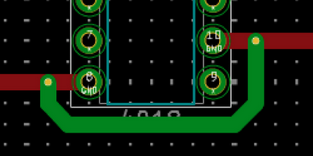
>>2923605My current stripboard design feels like that. Pic related, the green traces are jumpers. Probably going to clean things up a tad.
>>2923605i used to have some but had to take them out because i didn't have space
i'll try to add some though
the thing is that it's hard to add them without increasing by a magnitude the trace length
Messing around w/ a NodeMCU EPS8266 with an onboard OLED. I'm building a clock that hooks to WiFi and tells time from NTP service as a starter project.
I'm having some network issue. It worked fine once, then started taking longer and longer to connect to WiFi. Now it's refusing to connect, or my network is refusing its connection.
Code below. Is there a better way to implement the connection?
WiFi.begin(ssid, password);
while (WiFi.status() != WL_CONNECTED) {
delay(500);
Serial.print(".");
}
>search for something ESP32 related
>it's always ALWAYS arduino fucking garbage
>>2923777Unironically chatgpt has been giving me good results. Aa long as you verify the shit, it usually works.

hmmmm
md5: 6d6273cfb6ba93f0e415529ffafdde68
🔍
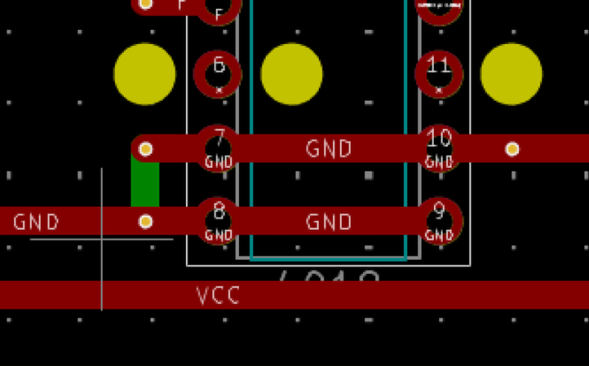
>>2923615start with this one
file
md5: b96295a31c35fbbe60df3b05c8535b5b
🔍
>>2923808Already did that, pins 7 and 9 are unused inputs so I tied them to ground anyhow.
>>2923615You got this down to one layer?
I’ve seen people do simpler things and use 4 layers because the company was paying for it, and now they can leave work at 2:00pm.
>>2923756looks like the 8266 onboard wifi hardware died. don't think its the polling loop problem.
>>29238502 layers makes every design easier unless it has a very forgiving topology. 555 timer pinouts are the opposite of this. I find it hard to believe that anyone considering 4 layers would do so with no extra benefit of shielding / signal-separation, or that it would take less time to route 4 layers instead of 2. Well maybe if you're used to routing certain components.
>>2923887lol that's pretty much what mine does.
I figured it out in meantime. I had to take a bunch of extra steps to get it to talk w/ my router, as well as define the DNS for ntp to work. Basically the code below.
// Local network configuration with static IP
IPAddress local_IP(192, 168, 0, 184);
IPAddress gateway(192, 168, 0, 1); // router IP
IPAddress subnet(255, 255, 255, 0);
IPAddress dns(8, 8, 8, 8); // Google DNS
WiFi.config(local_IP, gateway, subnet, dns);
>>2923888> 2 vs 4 layersHehe, the real reason is that we just go find some old board designs and dup them, then change shit until it’s working. Usually the board design that we duped was, itself duped from something else. So, 4 layer it is. Firmware is the same, probably why there’s still so many 8-bit cores out there.
I'm doing a 6-layer PCB at work. Shit's pretty much a nightmare with a 144-pin MCU, 32 cmos logic ICs in TSSOP16 and SO16, dual ethernet, a few memory chips & about 60-70 discrete transistors. Mostly prebiased BJTs and a few N-FETs. But at least with 6 layers the design is actually doable vs. 4-layer and especially 2-layer. It took a lot of convincing to step up to a 6-layer board. The client wasn't really happy about the extra expense.
>>2923916Why the fuck not just use DHCP?
>>2923932Why are you needing logic chips alongside a high pin-count MCU? Mega multiplexing for a big LED array or something? Or really high-speed asynchronous shit that would be better suited to a CPLD or FPGA?
>>2923988> DHCPBetter question:
Why the fuck are you not using a WWV radio receiver?
>>2924013Not everyone in the world has access to those transmitters. GPS on the other hand...
>>2922632>Chip VariantThere it is. Ty anon.
>>2923991> 6 layerGotta get creative. Think outside the box.
Routing power is a pain in the ass, so just lightly sprinkle some pin headers around in convenient places.
file
md5: 780fbcf491e36f495068f561ca634ce5
🔍
>>2923932> 32 cmos logic ICs in TSSOP16 and SO16I think 24 discrete logic chips is the cut-off point, where, instead you move to a PLA (or FPGA I guess we’d probably use nowadays).
You can just whip these up in your kitchen nowadays,
>make cool project for my old man
>refuses to use it
i hate old people
>>2924288Everybody gets old.
What was it?
>>2924290used a m5stick as the module
basically a smart mic that had transcription so he could easily note whatever he needed me to get from the store and a button that alerts me if he needed help, like they have in hospitals for nurses
some other minor stuff, clock etc.
even bought a raspberry pi to do the transcription/host the database

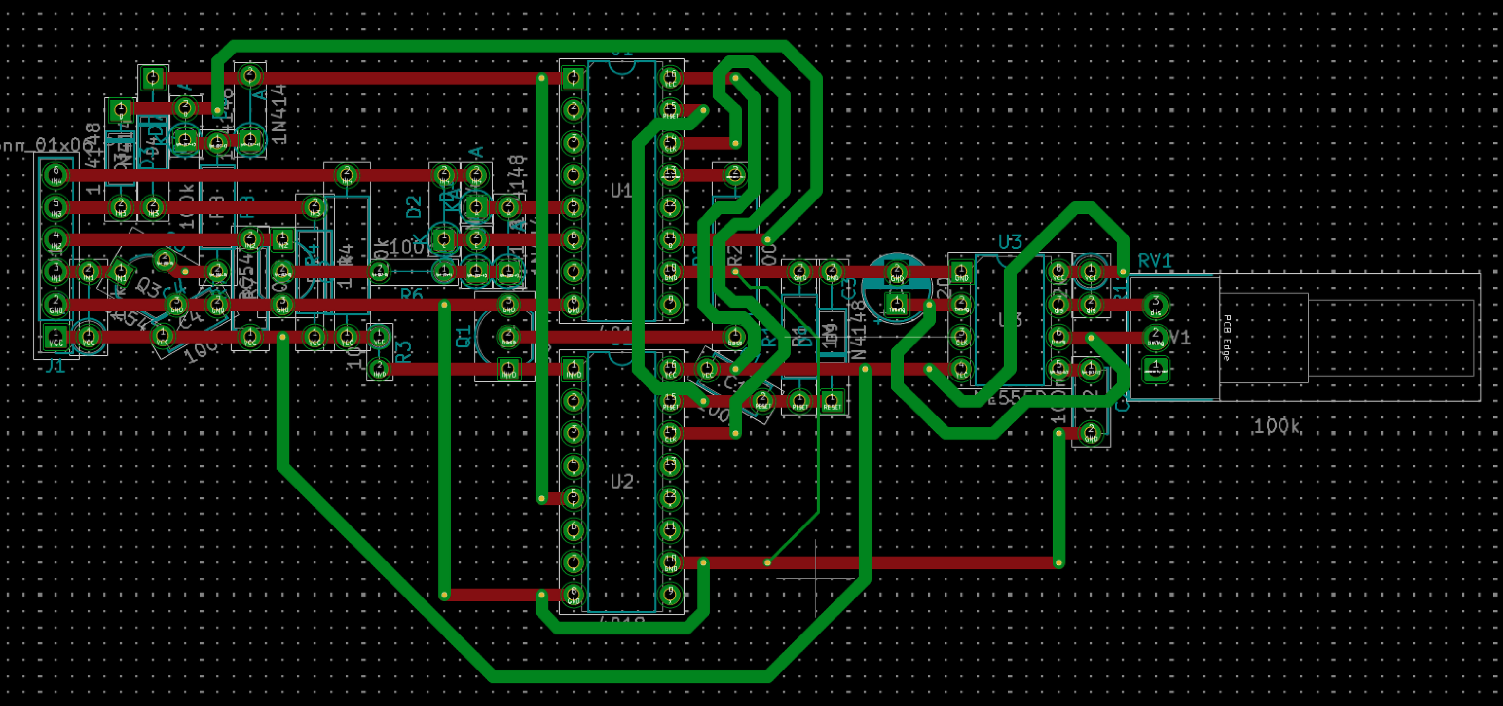
routing
md5: 81fa55108e3d745284a547d0b0b12794
🔍
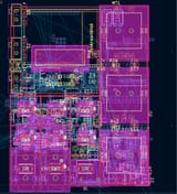
project update:
I've chosen the layout
six layers:
1: buttons, rotary encoders, GPIO expander n stuff
2: a big GND plane
3: not yet defined
4: power plane: i drew three rectangles for analog 3v3 and +-5V
5: GND and AGND planes, separated by ~5mm and connected at some point
6: esp32, connectors and audio stuff
i've tried using freeroute for routing some stuff. it gets kinda stuck at 30~50 unrouted nets which i'll have to route manually
it placed many vias.. i think i'll change them either into buried vias or microvias
the unconnected things are pretty hard to connect.. i ain't good at puzzles... damn
what do you think?
soon i'll publish every change made so far on the repo

over
md5: 61e0a03ee794bad6c6acaaec56692ad6
🔍
>>2924308it's fucking over
i really don't know how to finish this shit
>>2923991>>2924123Those logic ICs are all 8-ch muxes and 8-bit shift registers. Muxes route signals into a precision 16 bit ADC. That's what it does. It does electrical measurements and provides the results over ethernet. The measurement parameters, or modes, of all channels are set by the outputs of a long string of 8-bit shift registers. Those parameters change very infrequently. Maybe once a month or two.
>>2924368You better be sure you get good analogue MUX chips, a lot of test equipment still uses mechanical relays for a reason. Well relays are often pretty bad for thermal EMFs but you don’t get leakage and nonlinearity through them. Marco Reps experimented with a big diy rotary switch, but I think if he added a solenoid or other actuator to lift the contacts before rotating it would be sufficiently reliable.
>>2924312bodge wires
I'd try to figure out what can't snake around what and start over and try to group stuff together. then bodge whatever I couldn't solve
I've never used more than 2 layers though
>>2924312I remember this screen saver from windows xp
>>2924292> recreates the “memo minder” from risky businessExcellent!
>>2924312You’re design is wrongly conceptualizing the problem as conductive interconnecting traces.
I, too, was on that level at one point, early in my career. Don’t worry, though. It’s a phase and you’ll overcome it.
Eventually I realized the problem was to start off with everything connected (the initial copper layer before etching) and add the absolute minimum amount of insulating gaps in the right places on the copper layer to enable the circuit to function.
>>2924312Your design is wrongly conceptualizing the problem as conductive interconnecting traces.
I, too, was on that level at one point, early in my career. Don’t worry, though. It’s a phase and you’ll overcome it.
Eventually I realized the problem was to start off with everything connected (the initial copper layer before etching) and add the absolute minimum amount of insulating gaps in the right places on the copper layer to enable the circuit to function.
>>2924397>memo minderjust had a google of that, turns out they have a dementia aid with the same name
motion sensor that can replay saved recordings
pretty neat
>>2924384>bodge wiresno
come on i should be able to connect everything with a six layer pcb
>>2924400>Your design is wrongly conceptualizing the problem as conductive interconnecting traces.why? did you check the repo?
i did place the ground and power planes first
>>2924428at the moment I have ~37 unconnected nets
and some - hopefully minor - cleanup to do (rerouting analog ground plane-crossing tracks through the ground "bridge")
but i won't be able to work on it in the next two week
btw the repo is on github com/hydrastro/owo
>>2924400>Eventually I realized the problem was to start off with everything connected (the initial copper layer before etching) and add the absolute minimum amount of insulating gaps in the right places on the copper layer to enable the circuit to function.>misleading bordering on wrong>vaguely condescendingRobot waifu retard, is that you?
Nobody in their right fucking mind would ever take this approach for every net on even a moderately complicated board, even before taking into account things like differential pairs. In fact, I think the only placed I've ever seen this used is in power supplies and amplifiers. Significant current may be flowing through the conductors and using as much copper as possible to keep resistance/inductance down is helpful in that specific case. Doing it for signal traces is pure autism.
>>2924312far too complex. simplify it.
>>2924438>simplify it.how?
it's easier said than done :(
>>2924437> only look at the first instagram post you see about PCB design, and follow that, unchangingly for the rest of your life. And when a design gets too difficult, just give up and quit, rather than trying to look at it from a fresh perspective. Don’t forget to make your traces square with hard right turns because the autorouter does it that way.No, obviously, you’re not going to be able to do that for critical dimensional elements. That’s why we route the important stuff first and relegate the least critical stuff to last and ultimately jumpers and bodge wires. Although I have seen microwave hard line soldered onto PCBs as a “bodge wire” of sorts.
>>2924506>more irrelevant advice>completely ignoring the fact that the original advice wasn't relevant in the first place>while still condescending and attempting to look smarter than he isYou're ABSOLUTELY SURE you're not the robo wife autist?
>>2924513NTA, I've been sitting back watching some guy trying to eat an elephant for his My First PCB project, fucking fly wires everywhere, and
>>2924506 is right that you route the important stuff first. And just like chess, you have to get your pieces in the right place first.
>>2924513>>more irrelevant advice>>completely ignoring the fact that the original advice wasn't relevant in the first placethis
>>2924513>>2924530The project was posted.
I await your diffs connecting the isolated 37 nets.
Impress me with your abilities and do it on a 2-layer.
>>2924541i think there is some confusion between anons
>I await your diffs connecting the isolated 37 nets.soon or later i'll do that, i'm kinda busy with uni these days!
>Impress me with your abilities and do it on a 2-layer.nigga i think i'll struggle even with six layers lmao
>>2924541No, seriously, have you been tested for autism?
You're actually going to go "do it this way", followed by "no, obviously you wouldn't do it the way I just said to do it", and your response to being called out on it is a generic "if you're so great at it why don't you do it"?
You either have limited ability to comprehend what other people might be thinking, have trouble seeing things from alternate points of view, and hyperfixate on whatever point you're tying to make, regardless of whether it's appropriate/relevant. (I.E. you're a bit of an aspie)
OR
you're just straight-up a egoistic NPC with no introspective ability whatsoever.
Either way, I will not indulge this further.
>>2924437Reversing the idea of traces and interstitial space has always been commonplace in prototypes, look at the cuts made into the cladding to insulate those areas. It’s common again today with people running CNC machines to produce a PCB instead of etching.
help a retard out: are micro controllers just simple specialized boards compared to arduino which has yuge potential as it serves primarily for proof of concept and prototypes?
>>2924578
A microcontroller is just a not-PC that talks to electronic hardware directly.
Your mouse and keyboard each contain a microcontroller.
An arduino is a microcontroller, just a specific type with a well defined (though lame) environment for programming it.
>>2924565>It’s common again today with people running CNC machines to produce a PCB instead of etching.I swear this is because their shitty workflow prevents their CNC from carving copperless areas, I think you see them just carving along the outlines of the traces and pads fused together. With something like flatCAM you can correct for tool radius offset, make large isolation areas (not sure about slots), carve solder mask layers, and handle double sided boards, all out of gerber outputs from common CAD packages.
Any recs for eink displays that are reliable? For my first project was thinking of doing a to-do list with an ESP-32 that I can book on my desk. Found this one but wanna know if its better to go Aliexpress, since this is a bit pricey:
https://shop.pimoroni.com/products/inky-impression-7-3?variant=55186435277179
>>2924581A microcontroller is the central chip of an arduino. The rest of the arduino is just some periphery to make programming and prototyping easier. The point of arduino (any development board for that matter) is that once you're done programming the thing, you can easily make a proper PCB design with the microcontroller and everything else you need on one board.
>>2924622>once you're done programming the thing, you can easily make a proper PCB design with the microcontroller and everything else you need on one boardArduino a bit less-so, as it doesn't incentivize use of ICSP like most other dev-boards do. Bootloaders and serial debug printing were a fucking mistake.
>>2924623>ICSPWhy not just call it jtag?
>serial debug printingIt's the best way to debug shit.
Also I fucking hate Arduino.
>>2924619>was thinking of doing a to-do list with an ESP-32paying 69 pounds for a 7-inch display is kinda silly when ebay auctions often sell 7,8 and 10-inch Fire tablets for as low as 12 canadian pesos
>>2924629JTAG is a specific protocol, though some chips with their own protocol also often support JTAG too, like how STM32 chips use SWD but a lot can work with JTAG too.
>It's the best way to debug shit.printf debugging fuck yeah, though sometimes you have to get creative when you don't have a proper console port (or only have a UI), or the timing is too squirrely. I've had times where I logged a few bytes per loop to spare RAM then looked at the dump afterward.
>>2924679I thought JTAG is not a specific protocol, only somewhat standardized on the electrical level.
I hate most JTAG adapters. How easy is it to make one myself? I could use a FPGA.
>>2924705JPEG is sort of a meta-standard anyhow, it's about testing chips in general, you query a chain of data bits about your chip, as a big shift register like SPI on steroids. Micros use it by setting up registers for commands and data or something, so it might not even be consistent between two manufacturers.
Usually with microcontrollers it hooks up to a 20-pin IDC plug, but I can't tell you anything about the details of it beyond "sort of like SPI".
>>2924679> printf debugging fuck yeahFuck, no.
Imagine never having used BUFFALO on a 68HC11 over a serial port.
It’s hard to believe this is /mcg/
>>2924728> JPEGGo over to /g/ where they’re using “.webp” now
>>2924629>Why not just call it jtagBecause not all MCUs speak JTAG, a protocol which implies in-circuit debugging capability in addition to programming. AVR chips speak SPI or debugWire/UPDI, but the older AVRs like the 328P have to have debugWire enabled by setting some Efuses and it takes the place of the reset pin. ESP32s speak UART, but might have something like JTAG for debugging, some I believe can actually be debugged through native USB.
PrintF debugging is ass. Especially if you try to send more bytes than your serial comms buffer, or try to send a number variable. Either you send it natively as it’s value and get confused when your serial console tries to interpret it as ASCII, or you have to do a bunch of division to convert it to base-10 to spell it out in ASCII.
>>2924738Dude, I'm doing that RIGHT FUCKING NOW, on a 40-pin version even. Except BUFFALO is useless to me for anything except memory commands and loading S-records. It apparently wants you to hook up some external shit for the single step command to work. I never even got the built-in disassembler to work. (on a different chip, this one only has 4K buffalo)
I've written my own debugger that actually works (I had it working on a 6802 first and only needed a few changes), but for now I'm using microsoft basic to get shit working quickly. It's on a breadboard with an external ram chip, so when the fucker crashes because I looked at it wrong, it scrogs all over the ram and it's another two minutes to get back.
It's so fucking nice to just drop in a fucking print statement, though I miss hexadecimal.
>>2924739lol, I meant JTAG and wrote JPEG, ok stupid me
>>2924739>Go over to /g/ where they’re using “.webp” nowMost of /g/ hates webp, lol
Any thread talking about new image formats devolves into tribalistic shit flinging in record time
>>2924765> just drop in a fucking print statementWe used to and-off a couple of memory addresses or use gpio and hook them up to a latch then a couple of 7 segment displays and update them at various points to trace without using the serial.
IBM did the same thing the early RS/6000 workstations, every time we got a new aix rev, we load the tape and watch it boot for 30 minutes, then write down the last number on the led display and tell ibm since it had a good chance of halting.
Plus it looks cool when you bring chicks over.
>>2924752>ESP32s speak UART, but might have something like JTAG for debugging,Googling for ESP32 jtag gives an immediate hit that confirms that it supports it.
>PrintF debugging is ass.It's still the best method.
>>2924864hidden 7-segment displays are kino, I have a mobo with a post display
>>2924891> printf debugging It's still the best methodTell me you don’t know what an emulator, monitor, debugger or logic analyzer are without telling me you don’t know what an emulator, monitor, debugger or logic analyzer are.
>>2924950I've used all of these, arrogant loser. What kind of baby are you that all hardware you use has emulators and debugging support?
>>2924959If it doesn’t have an emulator or debug support before I start working on it, it will not long after I start working on it. It makes all development faster.
While we’re there, usually we get a forth interpreter going on it.
Be specific, what architecture doesn’t have a software emulator for it nowadays?
We have extended existing emulators to add support for different hardware, usually that’s not too difficult.
At least run code through the emulator to make sure it doesn’t immediately go haywire.
On hardware, you get unusual timing situations that can cause malfunction, but 90% of everything is caught by the emulator.
At least you don’t have to burn an eprom every time nowadays, eh?
>>2925084>If it doesn’t have an emulator or debug support before I start working on it, it will not long after I start working on it. It makes all development faster.You develop emulation for something you don't even know what it behaves like? If it's for example a bus, do you emulate all chips or devices to it? God you're so dumb.
>Be specific, what architecture doesn’t have a software emulator for it nowadays?You can trivially emulate most CPUs, but not the peripherals or connected hardware.
>usually that’s not too difficult.If you do trivial shit.
>At least run code through the emulator to make sure it doesn’t immediately go haywire.I normally make sure that the "boring" parts can be emulated or can be built as normal programs on the PC. That doesn't solve the real problems.
>On hardware, you get unusual timing situations That is another part that makes emulation for critical parts worthless, even if it's cycle exact behavior, because you can't emulate the hardware of third party vendors exactly.
>>2925165> You develop emulation for something you don't even know what it behaves like?Yeah, if it hooks up to the internet, we emulate the entire internet with perfect accuracy including unreachable areas down to the transistor level with spice.
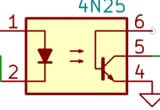
S56-09
md5: 4d401eee34b465c585c35f1d9adeb5d0
🔍
Why do many optocouplers have that base connection (pin 6). What's the purpose
>>2925275Hmm, I spy a VCA implementation…
Maybe it’s to allow you to use the output stage as a photodiode or a phototransistor?
>>2925275Sensitivity.
Plus override, I guess. Like self-test.
Also, why not?
>>2909001 (OP)>I need a part that does X and Y, with Z specifications. How can I find it?use DigiKey's or Octopart's parametric part search. Then purchase from one of the sellers listed above.
Please add a little tidbit about samtec as I find their method of allowing you to order a part from a wide category of parts and then configure additional options to produce exactly what you need which will almost always be ungoogleable or just out of stock and under a new name.
They also have a live CAD program baked into a little window so you can see each option physically changing your part and ensuring you get exactly what you wanted and or needed.
I wish I knew of other suppliers as good as samtec
I2C seemed like a great idea at first, but now I fucking hate it.
>>2924565>Reversing the idea of traces and interstitial space has always been commonplace in prototypesYeah, because it can make sense when you only have a few simple nets and/or you're handling currents too high for traces of any reasonable width. Even in the image you posted, the PCB isn't actually doing shit other than providing all of (what looks like) 3 common ground/power/signal planes, with every other connection freeballing in mid-air.
It's absolutely NOT and has never been a commonplace thing to do this for boards with dozens or hundreds of nets, with modern ICs switching low-current signals with frequency components in the hundreds of MHz or even GHz range.
Any esp-32 c6 boards that can connect to external antennas?
Want to build some super ZigBee rotuers
If I design a trace as a transmission line, that is whatever the calculator spits out after I feed it basic requirements. Will it then behave like it had no complex impedance, so neither produce overshoot, round edges or oscillations, at an arbitary mismatch, any length and any frequency (save for frequencies where black magic happens)?
>>2926101An external antenna literally just needs a wire.
I want to remote control a shitty consumer device. It has wi-fi, but all the cloud shit is just fucking annoying. It also has a remote control, which is probably just classic IR.
What's the easiest way to send the IR pulses I need? I'd think maybe connect an IR photo diode and an IR LED to some shitty MCU dev board and spend lots of retard effort to reverse engineer it.
>>2926237Yep.
There are one or two “standards” out there, like “philips” that you can get support on with some mcus.
Obviously, you if you have the remote, you can just “record” it, and “play” it back. You could probably, literally record it onto a cassette tape using a photo diode instead of a microphone, and play it back with an audio amp through an ir led instead of a speaker.
Even easier, walk yourself down to goodwill, grab a universal remote for a couple of bucks, program-in your device on the universal remote, and poke the buttons with gpio ports.
One you test it out, saw off the buttons altogether snd treat it as a self-contained IR module.
>>2926234Every c6 board I've seen doesn't have a antenna connector .
Can you access the antenna with pins?
Should I just sand off the PCB antenna and solder something on it?
>>2925393Could you link to it? Samtec looks like they just do connectors, and pretty specialised ones at that.
>>2926101ESP32-C6-MINI-1U-H4
There's also the 1U-N4 apparently. Both have something along the lines of a u.fl connector. No clue how it's soldered though.
>>2926237I looked into this too. There's an arduino library called IrRemote with a bunch of examples that should do what you're wanting, i.e. reading back infrared signals over serial. It can receive and transmit basically all IR protocols under the sun, though I'd consider ditching it for transmitting once you know what protocol it is. Just hard-code the transitions.
Because I couldn't feasibly take the remote home, I just pushed buttons while an IR receiver was hooked up to a DSO, allowing me to just write down the codes. See:
>>2915754.
>>2926263>Every c6 board I've seen doesn't have a antenna connector .Normally the connector is on the ESP32 module. Where do these boards have their antenna?
>>2926297>Mini-1u-h4That chip is exactly what I need but I can't find it on a board and I don't believe I'm capable of soldering a chip to a PCB myself.
>>2926327Most esp 32s have PCB antennas like picrel
>>2926330Oh that sucks then. DevKitC_V4, which I have in front of me, has a normal antenna connector.
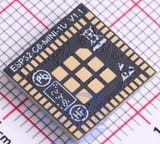
file
md5: af80f410d2a246ff36540dab3054d41d
🔍
>>2926330You may be able to order them pre-soldered onto a PCB via JLC or similar. That or order a full PCB with the ESP32C6 IC itself pre-soldered to it, along with all the supporting components it requires and that are normally under the metal cans on the modules.
That or buy a reflow hotplate.
>>2926333Yes that looks like a nice board but its chip doesn't support ZigBee
Only c6 does
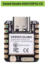
file
md5: 38995a2931807125d2c1cf908807cd21
🔍
>>2926330Aha:
https://www.aliexpress.com/item/1005006987272421.html
Though it seems to have both the onboard SMD antenna and the U.Fl connector. According to this document:
https://wiki.seeedstudio.com/xiao_esp32c6_getting_started/
>The RF Switch feature allows you to toggle between the built-in ceramic antenna and an external antenna by configuring GPIO14.>To enable this function, you must first set GPIO3 to a low level, as this activates the RF switch control.Also the ESP32-H2 apparently does Zigbee (and Thread, but not WiFi?).
>>2926338>>2926340I suppose there's a physical reason why it can't support all the common radio standards?
>>2926340Thanks big time that will work perfectly .
>>2926341>Physical I'd bet licencing and other legal bullshit
>>2926363>how to break fcc part 15
>>2926369Oh noooo it's a bluetooth class 1 instead of class 3
>>2926369>FCCI don't recognise any organisation with that acronym
>>2926204Anyone please?
The situation is as follows:
I'm building a HV boost converter, as high as the IGBTs will let me go before avalance. I had to fight dV/dT alot. Turns out it couples into the gate like crazy. If it arrives late you can active miller clamp it, if its earlier, while switching off that is, it's bad news. So I chose to shape the inductor response by making coils with low SFR and high parasitic C. Just putting a real C across validates the practicability of the idea. Now I am getting the desired new shape of a response. But what I am also getting is a lower magnitude higher frequency component. I was wondering is thats the SFR of either the trace leading from coil to collector / drain of the switching device.
>>2926476Forgot pic. If I'm not getting spurs I believe what is happening in the marked time interval is the line between inductor and switching device acts inductive, produces a spike according to its high SFR during switching off and that reflects back and forth a few times. It can be seen messing with my gate. Later the response from the inductor, that I actually want, arrives.
>>2915305can you just use a webcam and video editing software or something similar? I'm not even being ironic.
>>2926481You don’t think that is ordinary LC tank circuit ringing?
>>2926500Might be. After all every complex response you'll get from a passive is LC, since they always have parasitics. But it begs the question: Where do you reckon are the L and the C? Anr this brings me back to my original question:
Is a trace, that is designed to be a transmission line with close to 0 imaginary component and any real component, unable to produce ringing like that at any (reasonable) frequency and any mismatch? Sure it reflects stuff at the mismatch but having close to no imaginary part it wont produce spikes when large currents are switched, right?
I'm asking because I believe the L in the suspected LC tank is the connection from the inductor to the switch (inductor lead, wire, TO-247 lead) and the C just stray capacitance, hence a rather high SFR and very pronounced inductive behavior.
>>2926504This is what I'd much rather want. I brought power and target voltage way down to get something rather clean like this. Switching off happens on the transition on the green trace. After the appropiate delay the inductors response arrives, it's shape being dictated by it's SFR. The switch has long gone into high impedance state be the time it's facing the kV burden. Yes, thanks to dV/dT being somewhat high still some coupling into the signals does still happen as is evident. But this is manageable.
If you mentally removed the component shown in yellow from the trace shown here
>>2926481 you'd be left with some dampened oscillation in the MHz.
So I suspect it's induced voltage from a parasitic inductance in my boost converter. It's either being reflected back and forth or self inducing periodically, depending on how one wants to look at it.

smoooth
md5: 0ac1dc8e36b30161a790d2bd0baf2029
🔍
>>2926504Transmission lines always ring unless properly terminated. I doubt the circuit is even electrically long enough for TL effects to matter so the amount of ringing is determined by the Q of the circuit.
>>2926341it will be in the hardware of the chip itself, it's not like they put general-purpose full-duplex software defined transceiver modems inside those things, because that would be more expensive than dedicated hardware to modulate and demodulate specific protocols.
just imagine though, if we could hack something as cheap as an esp32 to be as powerful as a limesdr
>>2926484my webcam does not operate at 80 thousand frames per second
>>2926528By ringing do you mean reflecting a wave back and forth between the two ends? Because thats the whole thing I'm tryna get at here: It's one thing to have a signal bounce back and forth on your trace. On a trace with 0 complex impedance I'd expect the reflected signals to always be less in amplitude than the original signal. But if I am not mistaking such trace would not produce an arbitarily large voltage spike if there is an arbitarily large dI/dT on the trace.
I can live with my low voltage doing funny business on that trace. What I want to get rid of is radom ringing in the kilovolts.
So to rephrase:
An ideal transmission line, having no imaginary component to its impedance, will not cause i ductive spikes and this holds true regardless of any mismatch and holds true across the spectrum.
Is that right? It sounds logical, doesn't it? After all for an inductive spike you'll need an R+jX where X must be a positive number. If X were 0 or negative inductive spikes couldn't appear.
I want to get a little electric motor/engineering kit to basically fuck around with my 10 year old son. He's just interested in building stuff, it doesnt really matter what. i dont want to buy shit tier components. Something solid mid tier hobbyist level?
>>2926597Goal - > Plan - > Bill of Materials - > Buy components and tools. Not the other way round.
If you really have to manufacture a use case perhaps look around what you want to and can automate. Then make a sheet of requirements: Must have, should have, could have. Example: Must move window blinds, must adhere to programmed time intervals, should take current illumination into account, could have a full blown web interface.
Next plan the mechanical hardware, the electrical hardware and any code somthing like that needs.
Calculate and simulate as much as you can. Iterate and then make improvements.
Write your BOM. It will likely include a DC motor, SMPS (stay below 48V when letting children play with things), mosfets, passives, microcontroller, mosfet drivers, opto isolators, maybe status LEDs,some sensor and switches. Enclosure, potting resin, etc. Simple tools like soldering iron and multimeter. Might want a soundcard or ADC so you can use a PC or the microcontroller as a makeshift oscilloscope.
Then have fun building.
>>2926606Thanks for the reply, what you say definitely makes sense. I guess we've got to come up with a use case first, something fairly high torque I think would be cool like building a little winch or crane or something to that effect. Guess I need to do some more thinking, where do you buy your parts from? Stage 1 for us will probably be fairly analogue and then we'd add more complexity in with automation later
>>2926533You must have solved it already? But I wonder about the prospects of optical heterodyne detection without fancy lasers.
>>2926613It depends what I need. When I buy acting as a private entity I order almost everything circuit related from TME.eu as mouser, digikey and so on are less favourable imo with shipping etc.
Might be different if youre in the states.
Actual hardware is a different thing. If working with something new it's probably going to come from a store dealing in things related to the application. Otherwise youre often interfacing hardware you already got (say forklift DC motor as hydraulic pump or whatever) or I check classifieds for whatever obscure thing I need.
High torque? If other projects didnt use up my time currently I'd consider it a real fun quicky to make a tracked, fast, low CG, battery powered robot for lawn mowing and brush cutting on any slope. Maybe with ardupilot.org or openmower. de but that's just me and your and your sons specific kind of 'tism might have very different alignment.
>>2926508> induced voltageShield coils in ferromagnetic partition or enclosure, preferably mu-metal.
Add more capacitance or go for a full-on snubber network if you can’t do try-this-and-see-what-happens fixing.
At the cost of efficiency, add some extra loading resistors to dampen the spikes.
>>2926703I give up asking on here. I have one simple and clear question and no one ses to be able to provide a simple answer.
Also (you) missed the point entirely. The dV/dt induced by the inductor is wanted and after tuning the SFR of the inductor (as explained) very manageable at the current reduced power levels. Also the coil is of course completely shielded, the output wiring is coaxial with the shield carried all the way, its got two massive ground planes underneath and an enclosing shield soldered to the top layer ground plane.
What currently prevents me from upping the power is the response that evidently is not the coild response. Naturally the suspect are things like coil leads, trace and transistor leads.
Hence the simple question:
Can a trace that is designed to have 0 imaginary component to its impedance produce a dV/dT as a response to dI/dT as in V = dI/dT • L. I suspect not. And I am looking for either confirmation or repudiation along with an explanation.
But since aparently no one else here seems able to provide an answer either I will just go with my fucking initial reasoning and assume to be right, redo the fucking PCB and hopefully eliminate the undesired spikes.
Annoys the fuck out of me that I can't use Structured Text to program arduinos. Would be amazing to practice for industrial applications
>ablooboo just buy a PLC/simulate in TIA
no
>>2926872All I can say about this is: what the fuck?
>>2909001 (OP)>>2909001 (OP)Sorry to bother anons.
I founded an old headunit over there and since this is not a smart one try to made a dump from the memory chip, but stumbled in the fact idk how to decompile, extract or simply view the content.
know assuming the file is right and enough error corrected, how can I know the content, since it is not new, perhaps isn't too bloated and I want to learn what is the IC programmed to do.
the output of the file utility
>file : dataand the file manager says
>(application/octet-stream)using an hex editor at the beggining says
>00000020: 6655 7302 312e 3030 0000 0000 0000 0000 Ver01.00........But what to do next?
there are more like 50k lines but must are zeroes (padding I guess)
and other lines are unintelligible
>00001fe0: ca32 8d9e 56b0 7a44 1e56 1790 da1e e816 .2..V.zD.V......how to translate/interpretate it?
I was expecting some assembler like orders, but I have no idea what's the
next step.
Thanks.
>>2926913Structured Text is a programming language used for PLC's, programmable logic controllers, which are basically arduinos on steroids used to control every aspect of modern manufacturing. They also cost about 100x the price of an arduino. TIA Portal is Siemens's IDE for PLC programming.
>>2926917What’s the processor? Typically it will start at a certain address, and from there you can disassemble it.
Then you’ll get a feel for how subroutine calls work, and identify those as functions.
>>2927005Thanks for taking your time anon, I got surprised and found the next ics
>LC88FC3K0A 16-bit Microcontroller 768K-byte Flash ROM/47.5K-byte RAM 100-pin >78682320 1tn0b arm (can't pin down which family is) >s1402 2s.... (I couldn't see all, it's too small and it's half scratched) Now the unit is a sony dsx-a410bt, it makes me think the file dumped is for the lc88 since in the rom is 768kB, and the file is 780.3kB;from out there
>The LC88C300 series is a 16-bit microcontroller that, centered around an Xstormy16 CPU>ISA description:xstormy16 - Xstormy16 instruction set default-insn-word-bitsize: 32So it seems there is an implementation for this core for the gcc toolchain, then how can take advantage of it to translate the dumped file to assembler h-Rb - Rb registers and all that?
It makes me wonder then how the data received it is passed to the arm (guessing the arm does all the dsp and dac stuff to route to the amps and then the speakers,
I'm more confused since the firmware seems to be only for communications related not the audio signal itself.
Looked for the service manual to no avail.
Thanks a lot again
>>2927005and forgot, thanks for the advice!
Anyone here ever fucked with the daisy sneed? Got a bunch of those
>>2926925As someone who's used structured text before, I echo the other anon's question: what the fuck?
>>2927011Interesting stuff.
So, generally the gnu tool chain will want elf format or something, but generally you might have to “paste” pieces of the code in to get it to disassemble.
You’re looking at an embedded device, so it might just literally be running the application code directly with no operating system. So you have to find the on boot code execution vector, so read thr processor spec sheet.
You want to separate code from data, so if it’s interspersed that’s a bit if a pain, but I generally start manually by looking at function call sequences. Generally right before a call, or right after, they’ll push a bunch of registers so you’ll see a bunch of 0x008n instructions (for XStormy), where n is the register to be pushed, which will usually be incrementing since they’re gonna push them in sequence. Then they’ll pop the same reverse sequence at the end of the routine 0x009n followed by a ret.
Generally i’ve got the hex dump in a text file now with the assembly + hex machine code on the left and commentary on the right, with unknown blocks (possibly data) left in hex dump format.
Then I can just regen the file (after i make changes) and re-flash or re-burn.
>>2927122>So, generally the gnu tool chain will want elf format or somethingThe GNU linker supports multiple formats. You can also use objcopy to convert it to pure binary. You write a linker script to place the code and data sections where you need them.
Didn't really reads the post you replied to, so I might be very off.
>>2927127> use objcopyGood to know, thanks.
Personally, I was using objdump to disassemble chunks of ROMs. It felt very brute-force and ignorant.
Generally on an unfamiliar processor you’re going to make yourself a quick reference card too.
By that time, you’re also putting “XStormy16” as another line item on your résumé. <— don’t skip that step.
>>2926651Yes I already measured it.
The on and off time of the OOK is in the realm of 1ms, so even if the oscillation averages out I’d need about 2kS/s. I cannot see any situation in which I’d be able to undersample by a factor of 50 and somehow recover the comms information. If the shutter speed was fast enough and the repeat time was regular enough, in principle I could hold down the remote button for 50+ repeats and try to extract the data, but I imagine noise would be the critical limiting factor. Assuming the repeat time isn't evenly divisible by the frame time.
>>2926711This is the microcontroller general, not really the best place to ask about complex impedance. My assumption is no there wouldn’t be spikes, and if your coax length is terminated properly (e.g. 50R coax with 50R load resistor/antenna) there should be no significant reflection. But if it isn’t terminated properly, and you have a 1 light-microsecond-long coax length with a 500kHz input, the reflections could constructively add to a large ringing even with perfect coax. Because it’s still a delay line.
>>2927209> 1 light-microsecond-long coax length with a 500kHz input, the reflections could constructively add to a large ringingNice response
Not the the OP, but I had a long response that included measured trace excursions to cancel the negative effects that would be based on a bunch of calculations that would need to be done by OP, but deleted it…
Not sure what was going on there, some guy working for a company trying to fix some product?
Let’s say I want to send a normal NEC protocol IR signal with digital logic alone. No MCU or ASIC. I could chain some parallel-in serial-out shift registers together with preset bits tied to the inputs, and have a 38kHz oscillator driven the LED.
But because a low and a high shut take different times to transmit, I can’t just use a simple input clock, but rather use some sort of clock that varies its period based on the shift register output bit. Or a timer circuit on a fixed clock.
And then there’s the matter of sending the duplicated and inverted version of each byte, I can’t think of an easy way of doing that from just two shift registers. I guess 4 shift registers instead of two isn’t the end of the world, you could still send multiple commands by tying different buttons/logic to the third shift register and inverting those outputs being sent to the forth shift register.
Naturally, it is much easier to do this with a microcontroller. But discrete logic is kinda fun in its own way. If it takes more than about 6 logic ICs (diode/transistor logic doesn’t count) then I’ll definitely just do that.
>>2927523Holy shit, I could make it way simpler by putting inverters between the shift registers, instead of having 8 inverters between the inputs of the second pair of shift registers. Then it’s just pull-up resistors on each of those 8 inputs, and diodes going off to a few buttons that pull some of those to ground. Plus diodes that clock the latch input after the button is pressed. Then when the button is released, it would trigger a monostable that enables the main shift clock. I may be able to get away with the two shift registers and a hex Schmitt inverter, which I could use both for timing/oscillation and for inverting logic.
It’s probably pretty easy to use a diode and resistor to stretch the 1kHz oscillator period closer to 400Hz. This sounds like a nightmare to breadboard though.
>>2927738>I may be able to get away with the two shift registers*four shift registers
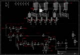
file
md5: d287e5e480b4af0a66722b98e62b948c
🔍
probably not feasible with vero-board, we'll see
>2928655>>2928655>>>2928655>>2928655>2928655NEW THREAD