/mcg/ - Microcontroller General: Serious Devboard Edition
Previous thread:
>>2909001
Here we discuss microcontrollers (MCUs), single board computers (SBCs), and their accessories, such as Atmel mega and tiny AVRs (Arduinos), PICs, ARM boards such as blue/black pill STM32, ESP8266/32s, RP2040, Raspberry Pi, and others.
For general electronics questions (power supplies, level shifting, motor driving, etc.) please ask /ohm/.
>where can I find verified quality microcontrollers and other electronic sensors or parts
digikey.com
mouser.com
arrow.com
newark.com
>but that's too expensive
aliexpress.com (many parts here are fake, particularly specific parts out of stock in the above sites)
lcsc.com
>I need a part that does X and Y, with Z specifications. How can I find it?
use DigiKey's or Octopart's parametric part search. Then purchase from one of the sellers listed above.
>how do I get started with microcontrollers, where should I start?
There is no defined starting point, grab a book and start reading or buy an arduino off ebay/amazon and start messing around. There are a plethora of examples online to get started.
>resources:
https://github.com/kitspace/awesome-electronics
>RISC-V microcontroller list:
https://codeberg.org/20-100/Awesome_RISC-V/raw/branch/master/RISC-V_MCU_development_boards.pdf
Anonymous
7/6/2025, 7:00:30 PM
No.2929363
[Report]
>>2929370
>>2928655 (OP)
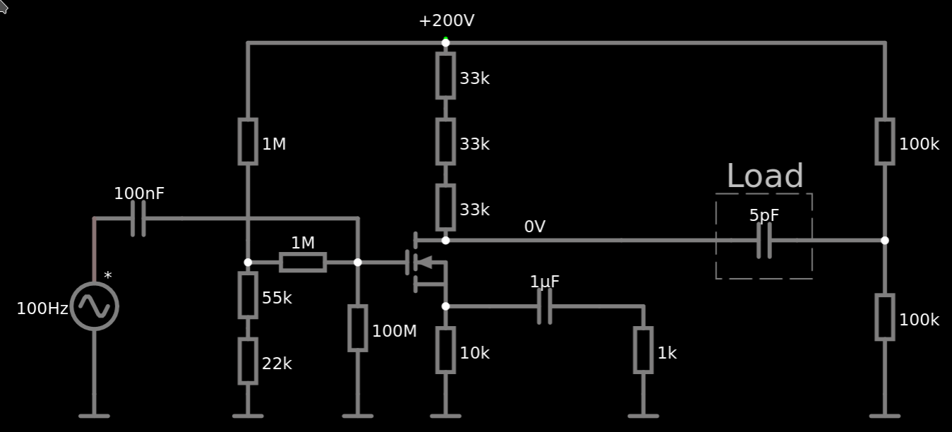
I want to sink 10, maybe 15 mA from uart mcu pins that i cannot determine the type of because it's embedded into something and non-reachable so i can't look up the specs. Is this current acceptable for uart connections on most mcu's? The sink is to drive a serial isolation optocoupler. The signal is 5V and outputs some data every second at 19200bps.
Anonymous
7/6/2025, 8:04:14 PM
No.2929370
[Report]
>>2929372
>>2929363
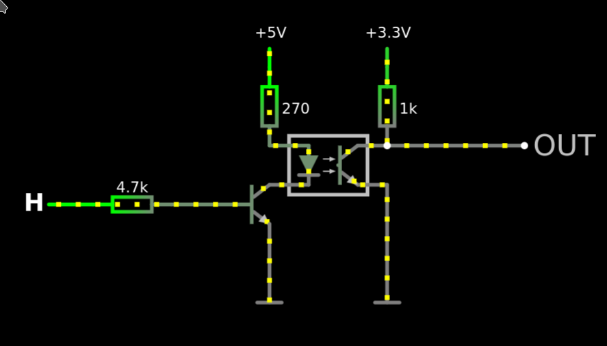
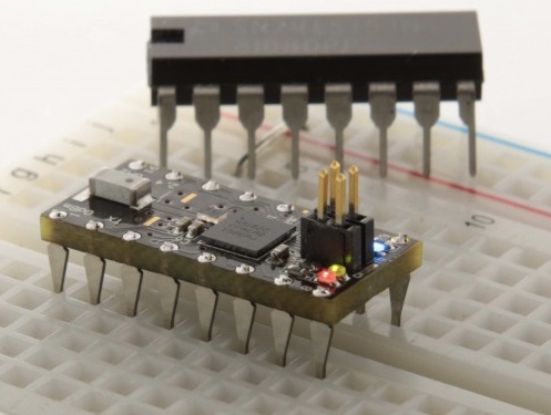
Probably not on newer MCUs. An older type like the ATmega328 (arudino uno mcu) would be able to but newer types would likely see a significant rise in Vol when trying to sink 15mA. You might see 1v when you should be seeing under 100mV. The exact voltage rise would be dependent on the mcu and may or may not be acceptable depending on the characteristics of you optoisolator. Also, I would be careful putting 5v on a digital input if the mcu is unknown. Newer types would may run on 3.3v rather than 5v and there is no guarantee that the pins would be 5v tolerant. Since 19200bps is very slow by modern standards, I would buffer the output with a transistor. I imagine the LED on the optoisolator is connected to 5v through a resistor and you want to connect the cathode to the mcu pin to turn it on when the pin is low? If that is the case you can go with normal non-inverted logic and connect the tx pin on the mcu to a bjt inverter. pic related
Anonymous
7/6/2025, 8:23:29 PM
No.2929372
[Report]
>>2929390
>>2929370
>I imagine the LED on the optoisolator is connected to 5v through a resistor and you want to connect the cathode to the mcu pin to turn it on when the pin is low?
Yes that was my plan.
But this pic inverts the signal right?
Anonymous
7/6/2025, 10:16:41 PM
No.2929390
[Report]
>>2929392
>>2929372
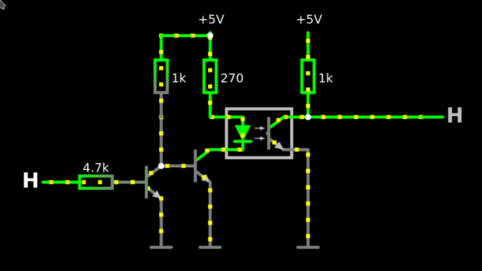
Yes the output on the isolated side will be high when the mcu output is low. If you don't want this you can invert the logic on the mcu. If you can't change the mcu firmware, you can add another npn to invert the signal. Since your baud rate is only 19200 the difference in propagation time will be negligible.
Anonymous
7/6/2025, 10:30:20 PM
No.2929392
[Report]
>>2929399
>>2929390
What are you retarded? Just put a pull-down resistor on the phototransistor instead of a pull-up. It’s floating, it doesn’t have to be common-emitter.
Anonymous
7/6/2025, 11:03:58 PM
No.2929399
[Report]
>>2929392
Good point. With 5v logic a 0.7v drop can be tolerated.
Anonymous
7/6/2025, 11:55:09 PM
No.2929404
[Report]
Should work. Thanks guys
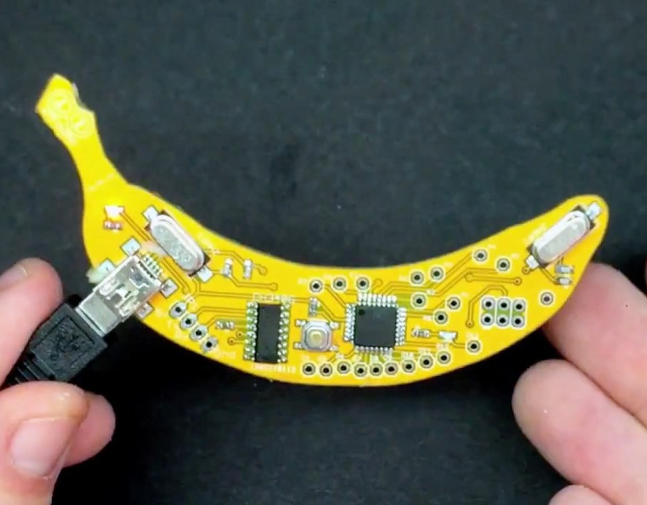
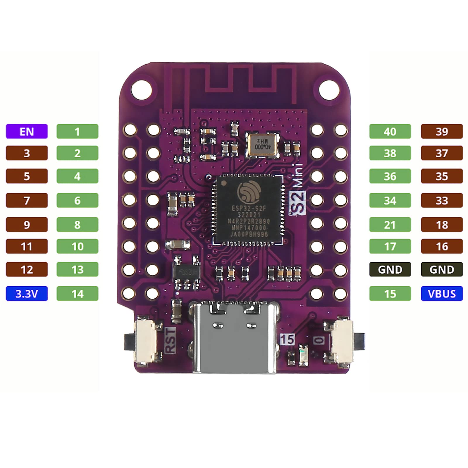
>>2928655 (OP)
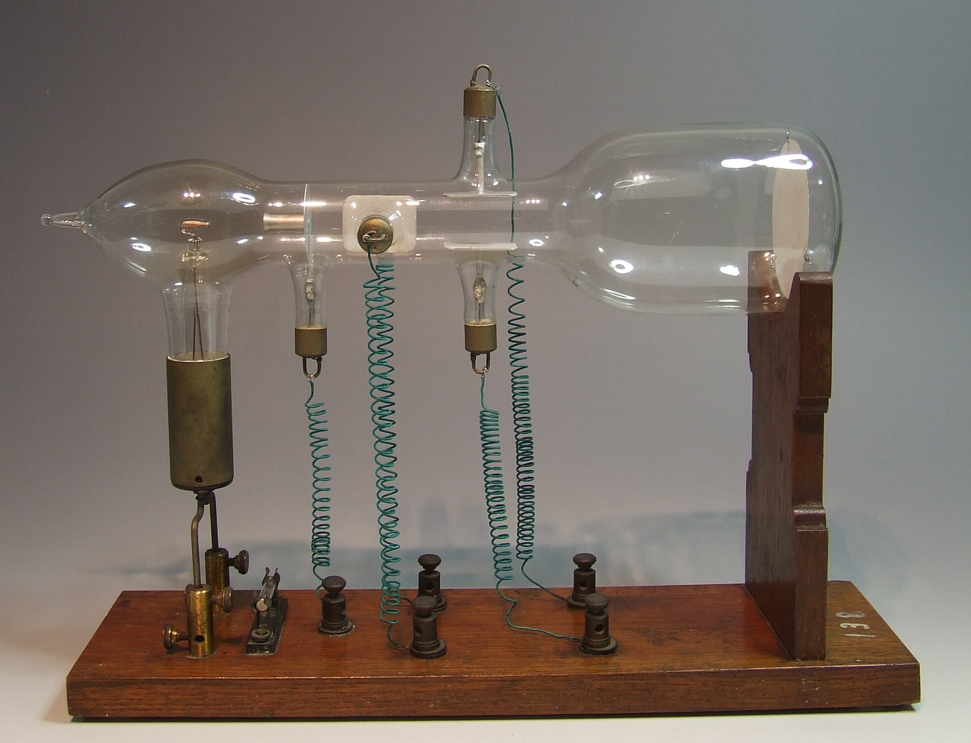
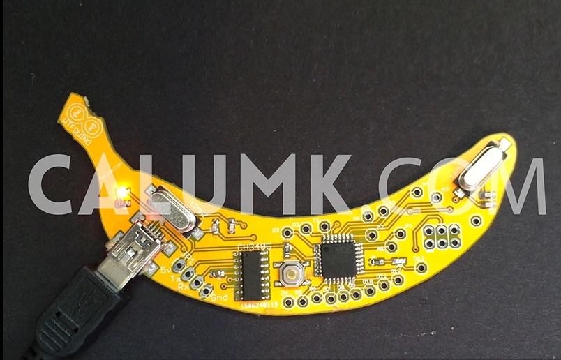
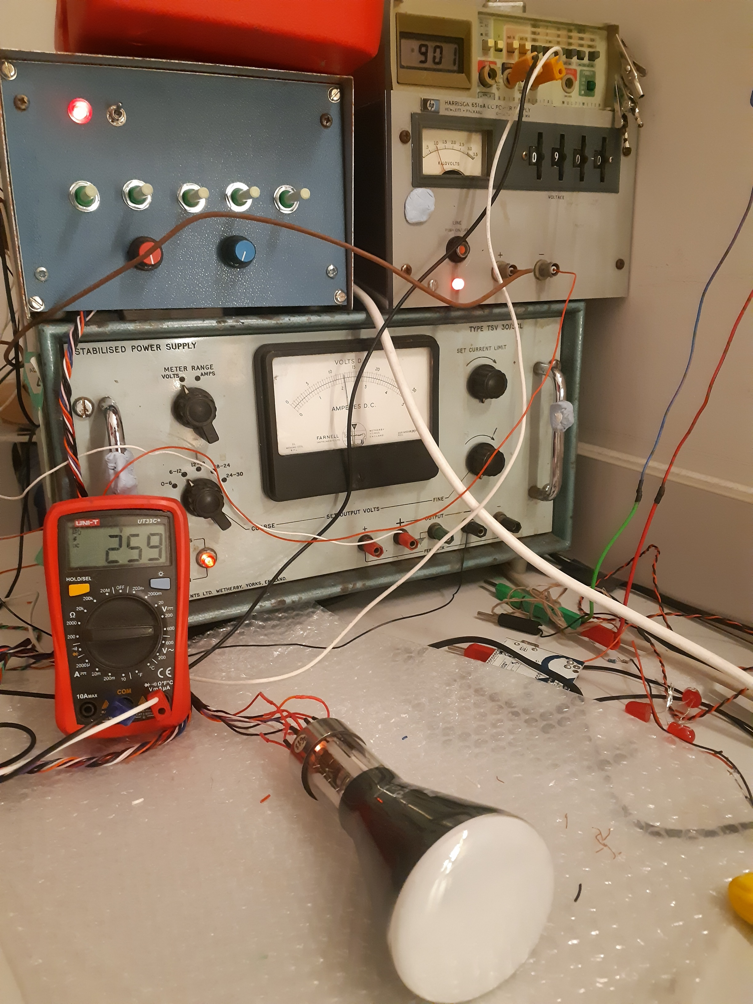
Do you have the sauce for the banana dev board or a high resolution pic? Here's some CRT porn in exchange
Anonymous
7/7/2025, 3:38:07 AM
No.2929437
[Report]
Anonymous
7/7/2025, 4:26:55 AM
No.2929443
[Report]
>>2933043
>>2929405
I’ve never been able to find a source file for the WTFduino, but I’m pretty sure it’s just a 328P nano.
That CRT doesn’t look to have a front electrode to dissipate the charge from the phosphor. Man I want to make a vector display. Good thing we have laser galvos. Or maybe I should feed a component/VGA signal into a laser galvo to make a raster display? I should look into that.
Anonymous
7/7/2025, 4:43:32 AM
No.2929451
[Report]
man, the (tr)usdx HF transceiver is insanely impressive for an ATmega328P. I think they’re doing I and Q decoding AND voice input and output. Somehow. I don’t see any mixers or filters on their circuit.
I just spent the better part of somewhere between 4 and 6 hours figuring out a relatively simple and stupid bug in some code for a pair of STM32s trading a pair of bytes and ACK signals over UART.
NGL I kind of feel like shit about this, and how often things like this happen to me. Is embedded dev actually just like this? Does it get better? Is there some magic trick to not think like a fucking retard? Or is the best course of action about 50g of acetaminophen and a bottle of everclear?
I only do this as a hobby and I'm not that experienced, so I have no real context for whether or not struggling so badly for ridiculous amounts of time on what end up being relatively simple single-line problems is an everybody issue or just a me issue. I've heard plenty of joking about it, but I don't have a clue how much of that is exaggerated for comedic effect.
Anonymous
7/8/2025, 2:55:58 PM
No.2929807
[Report]
>>2929798
Is it something where an oscilloscope would have helped?
Sometimes just not being completely blind to what's on a wire that makes a big difference, and it can be easier to hook up than a printf debug on something with no console.
These cheap handheld ones are only like 80 bucks or so, and well worth it.
Anonymous
7/8/2025, 4:32:02 PM
No.2929819
[Report]
>>2929798
I made an app dev debug something for weeks because my firmware had a trivial bug.
>>2929798
Are you using debugging via GDB or otherwise through your IDE? Printf “debugging” doesn’t count. Being able to step through clock-cycles and see what values are in your registers and on each pin can be very useful for tracking down spurious bullshit. Or so I’m led to believe. Doing this on two MCUs at once may not be easy, but it should be doable.
I think CNLohr wrote some sort of development environment that made compiling and uploading code to STM32s really damn fast for more rapid prototyping, but I don’t know if it includes debugging.
While I wouldn’t recommend asking an LLM to write a program for you, asking an LLM why your code has this buggy result may steer you in the right direction.
You could also take the ASIC+analog pill and avoid anything you have to program. Most projects can be greatly simplified with the right hardware, and even if the microcontroller can’t be taken out of the equation maybe you can use an existing codebase for it, or make the programming far simpler. Why solve a problem today in software if you could have solved it yesterday in hardware?
Anonymous
7/9/2025, 12:35:09 AM
No.2929910
[Report]
>>2929887
>I think CNLohr wrote some sort of development environment that made compiling and uploading code to STM32s really damn fast
"make"?
>asking an LLM why your code has this buggy result may steer you in the right direction.
lol
>>2929798
>Is it something where an oscilloscope would have helped?
I already have a DSO. I'm not a complete novice here, though perhaps only just barely this side of it. That's part of the problem. I feel like I shouldn't be fucking up in ways this stupid at this point, at least not for this long.
>>2929887
>Are you using debugging via GDB or otherwise through your IDE?
GDB via the STM32 extension for VScode. Which actually was what ended up being part of the problem: It didn't occur to me that the peripheral registers have no way of knowing whether they're being read/written by the MCU itself or by the debug...meaning that flags that are set/reset on register read are flipped "at random" when the debugger pauses the MCU and checks register values.
IDK, I guess I'm mostly just looking for confirmation that either failing this hard is semi-normal or that I am, in fact, retarded.
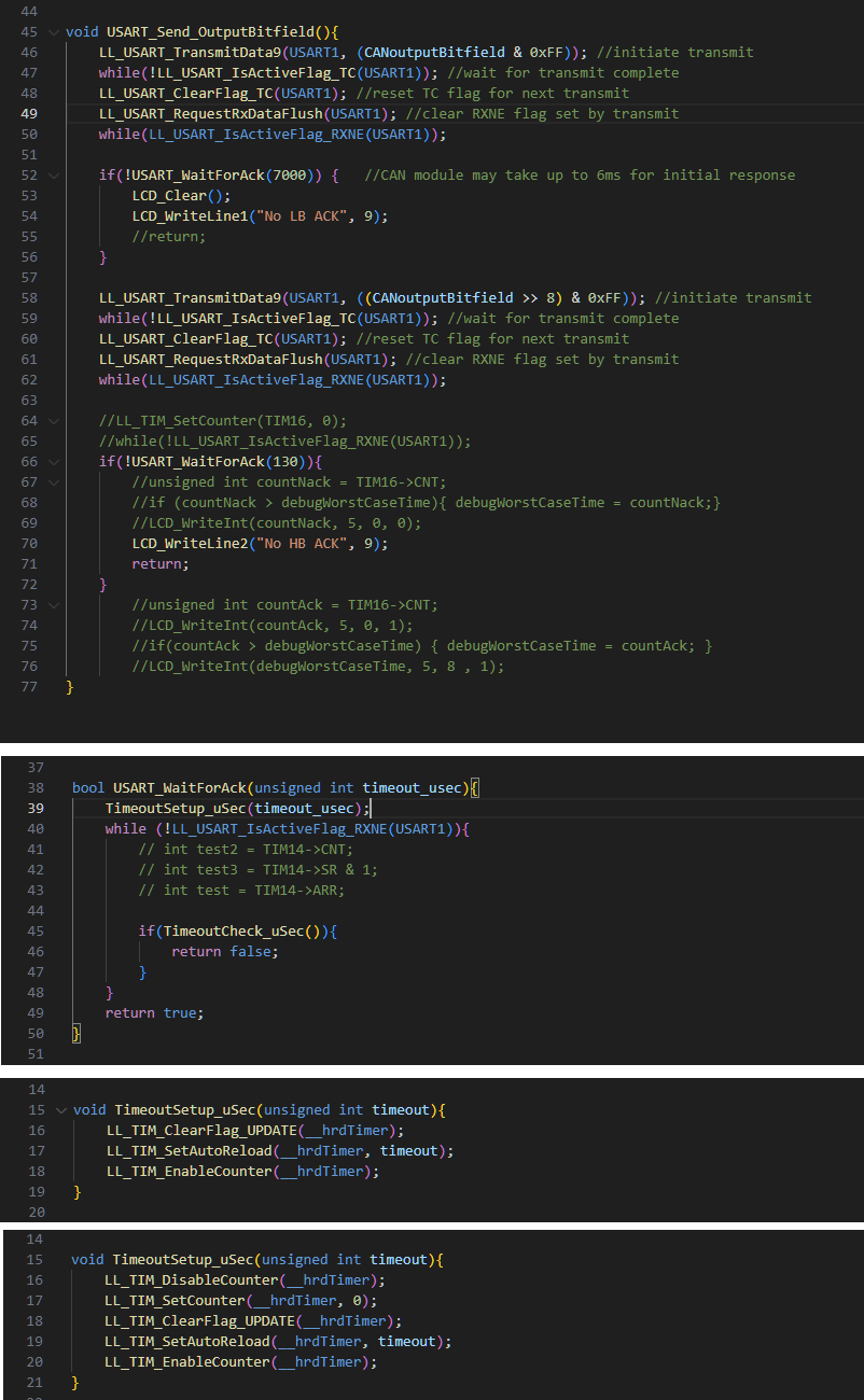
Just for reference: Picrel for what ended up being the root of the problem. I couldn't figure out why the timeout for the first byte always worked fine, but the second wouldn't time out. USART_WaitForAck() would always return true (transfer received in time) even with impossibly short wait times...unless the receiving MCU was held under reset and not responding at all, at which point it would time out as expected. I eventually set the receiving MCU to just never send the second ACK and measured how long the timeout actually took, which was suspiciously close to 65535µs. Turns out, when I wrote the TimeoutSetup_uSec() routine at the core of the delay, I had implicitly assumed that the counter would be stopped at the start of that function. But, if the delay is long enough that it can be called again BEFORE the counter hits the set AutoReload (maximum/top) value, setting another, lower AutoReload value will cause the counter to dodge the original and the new timeout value won't be hit until the counter overflows.
Anonymous
7/9/2025, 1:22:40 AM
No.2929924
[Report]
>>2929990
>>2929923
(cont'd.)
It just seems so fucking obvious now that I see it. Yeah, other problems took up a portion of the near full day I spent on this (like the debug clearing flags, or that it's not pointed out in the datasheet that the overrun detection bit being set practically halts the entire USART peripheral, or any of half a dozen smaller code bugs), but saying that just feels like cope.
Anyway, thank you for coming to my blog, have a nice day.
Anonymous
7/9/2025, 9:15:26 AM
No.2929990
[Report]
>>2929923
>>2929924
I didn't try to understand your problem (tl;dr), but it's common that shit close to hardware, especially timing related stuff, can be hard to figure out. It simply drains a lot of time and energy. I'd recommend to have good ways to debug, like using a scope to view what happens on the UART, or making sure gdb shows real values (it often lies to me).
Bought a ESP32 and decided to run some tests with a 4-digit 7-segment display. I wired it and uploaded the sketch from this
https://microcontrollerslab.com/esp32-74hc595-4-digit-7-segment-display/
It works fine for any number up to 5555, but entering any number higher than that into the serial monitor causes errors. Random numbers, symbols that aren't even numbers, and blank screens. I looked through the code and I didn't see anything wrong with it, and I swapped out the 74HC595, resistors, and wires incase there was any fault there.
Is my ESP32 just borked in a completely retarded way?
Anonymous
7/11/2025, 4:19:23 PM
No.2930577
[Report]
>>2931163
>>2930572
>It works fine for any number up to 5555
how certain of you of this statement? that would be a very strange bug, as theres nothing very special about numbers higher than 5555.
does 7777 work?
Anonymous
7/11/2025, 6:17:27 PM
No.2930611
[Report]
>>2931163
>>2930572
have you tried another code or ide with that board?
Anonymous
7/12/2025, 8:51:53 AM
No.2930775
[Report]
>>2931163
>>2930572
Probably shitty code. That does not sound like a hardware problem. If you write the code yourself, not only will you understand why it works, but also understand where to look if it doesn't work.
Or ask an AI to do that for you, jeez.
Anonymous
7/14/2025, 12:10:24 AM
No.2931163
[Report]
>>2931203
>>2930577
Because the moment I noticed the bug I went through the numblers. First by the thousandth state, then the hundrendtg stat, finally the tenths, I didn't dive into the single digits because literally ever single numble above 5555 glitched out.
>>2930611
Yeah, I ran a basic blink sketch on this board multiple times with zero errors.
>>2930775
I spent all of Friday night and half of yesterday going over the code and see zero issues. The code should work. The board should work, in reality nothing works.
I pulled out my Fluke and tested every resistor. They resistors I used were 220 and rated at ±1 but actually read at 217.3Ω. I sat down and did the math and that variance should not in any way effect this. I switched out the 74HC595 with an honest to God Texas Instruments 74HC595. I replaced the 7seg4 with three different ones I had in my bench stock and got the same results ever time.
Anonymous
7/14/2025, 3:12:57 AM
No.2931203
[Report]
>>2931216
>>2931163
Those symptoms are not indicative of any issue in hardware, it’s definitely in the code, even if it isn’t obvious. Assuming you’re not in a workflow that has GDB available, try putting some printf() statements at various points in the code. Try to send 5556 to the screen and check key variables for overflow or corruption. Displaying binary values as decimals requires division by 10, and most
Microcontrollers don’t have hardware division, so memory might be a problem. If you don’t calculate the last digit and leave it as 9 all the time, do you still get the bug?
Anonymous
7/14/2025, 4:03:11 AM
No.2931213
[Report]
>ardushitto code written by retards
kek
Anonymous
7/14/2025, 4:13:20 AM
No.2931216
[Report]
>>2931228
>>2931203
it was in the code
Anonymous
7/14/2025, 5:47:40 AM
No.2931228
[Report]
>>2931232
>>2931216
Was? You fixed it?
Anonymous
7/14/2025, 5:57:39 AM
No.2931232
[Report]
>>2931247
>>2931228
yah, I am a retard
Anonymous
7/14/2025, 9:06:03 AM
No.2931247
[Report]
>>2931232
Explain the problem so we can learn. And laugh.
Anonymous
7/20/2025, 1:09:03 PM
No.2932795
[Report]
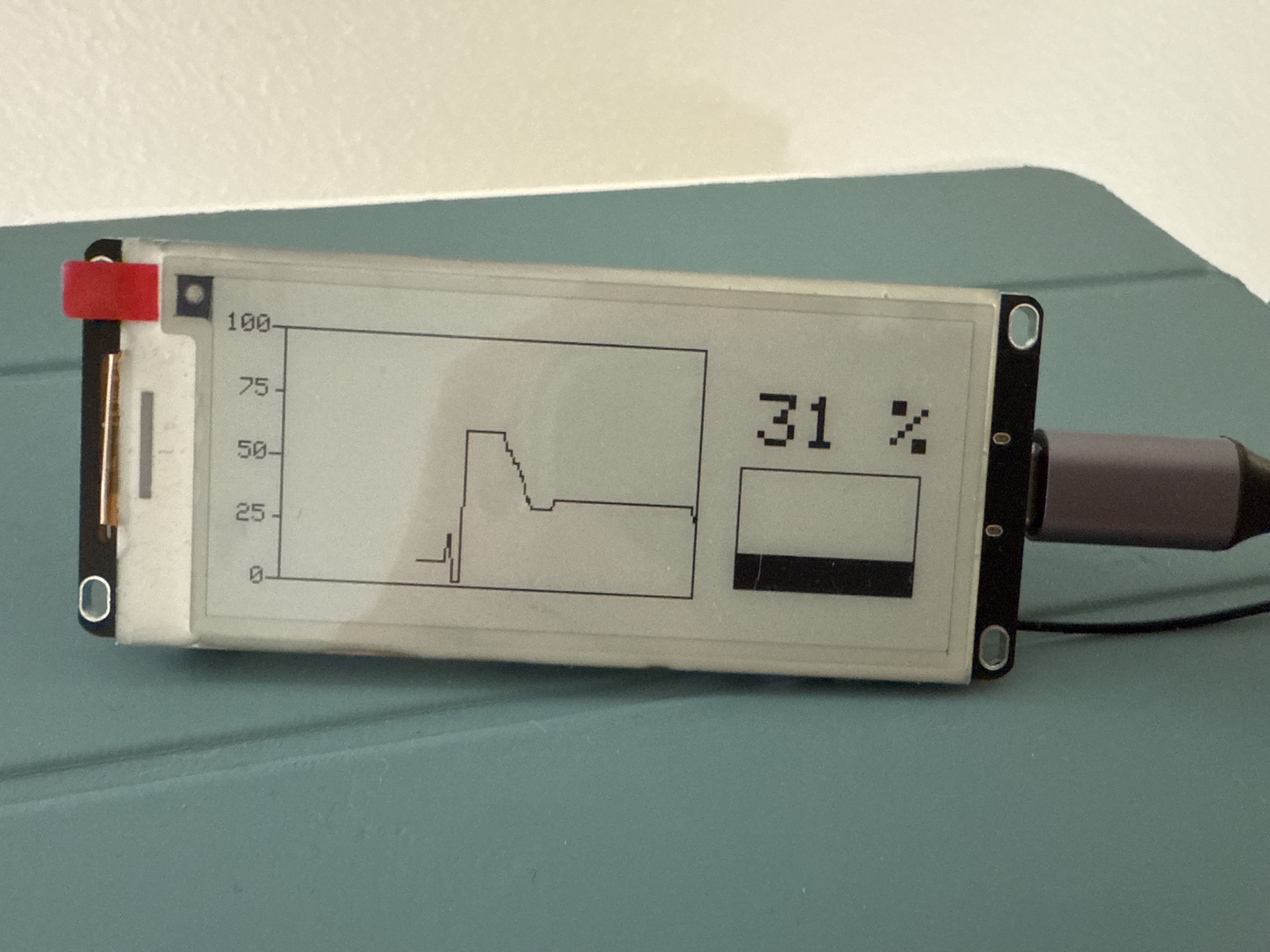
I wrote a little something to monitor sensor data and display a history. Now I'm wondering, are there better libraries for this? It's an ESP32, so I might even do it in micropython which could make use of the time information.
Anonymous
7/21/2025, 10:44:14 AM
No.2933043
[Report]
>>2933058
>>2929443
>front electrode to dissipate the charge
You mean the aquadag coating? This tube was a 1930s demo piece so I'm guessing that aquadag was either not a thing back then or they didn't bother because it was just a demo tube.
>Man I want to make a vector display
If you want to use a CRT it's pretty simple if you're willing to work with high voltage. Picrel was my setup before I dismantled it. I plan on coding an mcu to connect to the drive circuitry so I can play pong on the CRT in the near future so I may post here if I get around to it.
Anonymous
7/21/2025, 12:45:24 PM
No.2933058
[Report]
>>2933180
>>2933043
>aquadag
Yeah, though I didn’t know it stopped short of the phosphor. Guess the electrons can still move to it after striking the screen. Bet if they put an ITO layer under the phosphor too you’d get less static buildup.
>MCU for pong
Cmon man, pong is the perfect project for a diy analogue computer. Can probably make it in 40 ICs or so.
Anonymous
7/22/2025, 12:02:09 AM
No.2933180
[Report]
>>2933058
>Analogue computer for pong
To be fair I find this idea appealing and was initially going to go down that route since I prefer hardware over software but I have my hands full with other projects at the moment and it should probably be possible to write the program for it in a single day. I've already prototyped one deflection plate amplifier and it works fine at low frequencies. I didn't have any high voltage BJTs so I had to improvise and use IRF740s (not suitable for use in their linear region, I know) but even with those MOSFETs the deflection plate drivers are probably more than fast enough for pong. I've built up another amp to go with the first one so I can have independent control over X and Y deflection but I haven't tested the second one yet.
Anonymous
7/24/2025, 11:07:45 PM
No.2933911
[Report]
>>2933956
Micropython, I kneel. Why didn't I try this before? It's so much easier in the field than getting my laptop with esptool, platformio or the Arduino IDE.
Anonymous
7/25/2025, 2:35:05 AM
No.2933956
[Report]
>>2935746
Anonymous
7/31/2025, 8:38:26 PM
No.2935481
[Report]
>>2935565
How did ARM manage to make the MRC and MCR so completely retardedly over-complicated and unintuitive? Every time I'm trying to wade through their shitty docs and try to match these psychopathic IDs I want to kill myself. Fuck ARM.
Anonymous
8/1/2025, 6:16:54 AM
No.2935565
[Report]
>>2935593
>>2935481
Take the RISC-V pill
>>2935565
RISC-V has a similar mechanism, but instead of a tuple of 5 names, each register has only one name. One potential mistake they made when they defined the ASM language is how each register has an actual name, instead of specifying it as number. Now you need an updated toolchain each time you want to access a newer CSR.
Anonymous
8/2/2025, 2:41:06 AM
No.2935693
[Report]
>>2935686
Seems to have a very low number of system registers, not like ARM ("it must be extensible until the heat death of the universe and even after aliens enhance our brains to think 6-dimensional") or RISC-V ("I will design it to be extensible with random shit until I leave the industry")
Anonymous
8/2/2025, 5:50:55 AM
No.2935745
[Report]
>>2935593
> how each register has an actual name, instead of specifying it as number
On Isreal Inside(tm) I’ve stopped using RAX and, instead, use R0. To prepare for amd128 which is in the works, which will, again, double the register file cardinality.
Do likewise, gents.
Anonymous
8/2/2025, 5:56:02 AM
No.2935746
[Report]
>>2933956
It’s taking a toy language, making another, superficially similar language, but one that hardly does anything that the original one does making it more of a toy. The only thing left is some of python’s worthless syntax. And by worthless, I actually mean that it’s a blight on the industry.
Anonymous
8/2/2025, 6:00:41 AM
No.2935748
[Report]
>>2935686
Super H is a reasonable choice, however ARM already stole one of it’s main features: code density. In ARM this manifests as the Thumb and Thumb 2 instruction sets. Without that, the roles of SuperHitachi and ARM would be reversed and we’d be living in a utopian society.
Anonymous
8/2/2025, 12:30:58 PM
No.2935795
[Report]
>ARM has 4 instruction set encodings
Or was it 5?
Anonymous
8/2/2025, 10:10:59 PM
No.2935852
[Report]
>>2941253
What's a good j-link clone?
I'm trying to build a tachometer to use with a nodemcu, the issue is I want to use interrupts to count the pulses, but when the edge falls, it triggers hundreds of interrupts.
I tried a low pass filter and it still didnt work
Im having this issue with both optical and magnetic sensors
I do not have an oscilloscope
>>2935943
RC low-pass filter followed by a schmitt trigger. And twist your wires together, maybe even add a ferrite, since automotive environments can be electrically noisy. Could add some dead-time before you re-enable interrupts too.
>>2935948
>RC low-pass filter followed by a schmitt trigger.
that wont work very well, as OP has found out
3 things that will work
- integrator (diode, cap, resistor) followed by schmitt trigger
- non-retrigerable monostable, such as a 555
- SR latch
for more, do google image for ''switch debounce''
not having a scope means you should go with a method that doesnt use RC time constants as you'd be adjusting them blindly
Anonymous
8/3/2025, 8:03:16 AM
No.2935953
[Report]
>>2935952
forgot one:
since you're using a 'puter, you can debounce in software
wont work if you insist on using interrupts, tho
Anonymous
8/3/2025, 8:08:15 AM
No.2935954
[Report]
>>2936514
>>2935952 (You)
forgot one:
since you're using a 'puter, you can debounce in software
wont work if you insist on using interrupts, tho
or maybe it can
after you get a first interrupt, disable that interrupt for the next 15-20 msecs, creating a dead zone just like a monostable would
Anonymous
8/3/2025, 8:11:36 AM
No.2935955
[Report]
>>2935952
>integrator (diode, cap, resistor)
>diode
Those sensors generally don't have push-pull outputs in the first place, so the diode is probably superfluous. It should pull the output down fast, and the pullup resistor and cap will make for a slow rise.
Anonymous
8/3/2025, 4:54:44 PM
No.2936051
[Report]
>>2936182
>>2935948
weird thing: I connected the same sensor to an arduino uno and the interrupt works correctly, but the same setup on the nodemcu makes it trigger like 4k times when it should trigger once
digging around online, this seems to be a weird issue with the nodemcu, apparently it is too fast and if the step rise is too slow, it registers several times. still, over 4k is way too many times
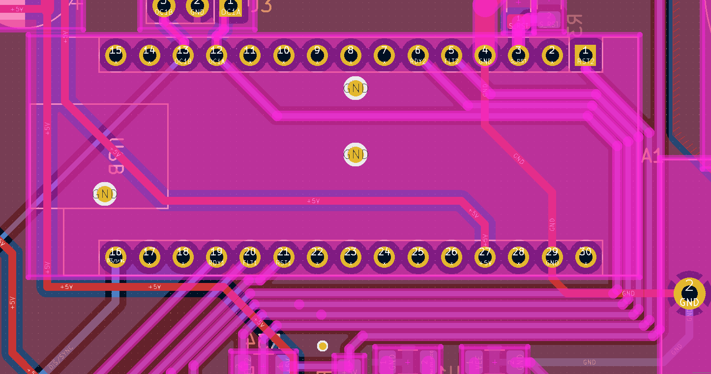
wassup my niggas I am back
the news are:
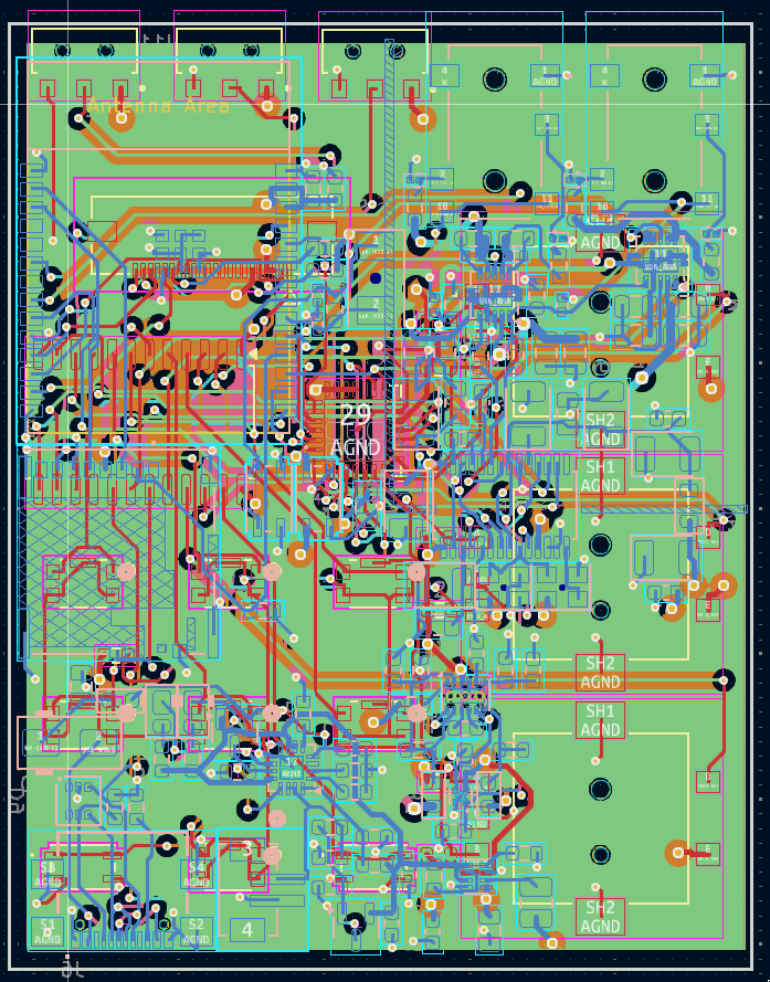
-I have finished the PCB design: i just need a review and then order prototypes.
-for some reason i don't fucking know what's the problem with my bill of materials n shit.. i can't order this thing on JLPCB
-my depression got way worse so I may not be working on this a lot but i'll try my best
-my new goal in life is to get in a nursing home and live the rest of my life sedated until either big oof or euthanasia
btw the repo is still here if u wanna fuck around (maybe you'll find out) github com/hydrastro/owo
Anonymous
8/4/2025, 2:03:04 AM
No.2936154
[Report]
>>2935943
as the prior anon said, use a schmit trigger. ESP interrupts need sharp edges. Had my fair share of problems trying to use those cheap rotary encoders
Anonymous
8/4/2025, 4:09:04 AM
No.2936182
[Report]
>>2936252
>>2936051
Sounds like it’s spending too much time in the 25-75%Vcc range or so where logical 1 or zero isn’t defined. You need a Schmitt trigger or a few microseconds of delay before you enable interrupts again. A low-pass filter will only make the problem worse, but might still be a good idea to remove some noise if the other methods don’t work fully. You may also be able to improve the response speed by using a lower-value pull-up/down resistor on the sensor.
>>2936145
I may check later if I remember, but are you using the JLC fabrication toolkit addon for KiCAD? And adding the LCSC PART # or whatever in KiCAD’s BOM tool as the extension instructs? You also have to watch out for SOT-223s and other asymmetric footprints, they often come out off-centre by default.
Anonymous
8/4/2025, 10:04:40 AM
No.2936252
[Report]
>>2936322
>>2936182
>but are you using the JLC fabrication toolkit addon for KiCAD?
uuuhh no
didn't know it existed lmao
>And adding the LCSC PART # or whatever in KiCAD’s BOM tool as the extension instructs?
not really
though I have all the parts in a list on DigiKey
>You also have to watch out for SOT-223s and other asymmetric footprints, they often come out off-centre by default.
wtf why? damn that would suck
i'll try to check things out
thanks!
>>2929798
>is embedded dev like this
if you only know how many times I've been in the lab after 3 weeks of dispair only to realise all my problems stem from a single most stupid mistake.
It doesn't get better.
Example: The company pulled an old prototype back out. I was told to set it up and get it running. It had some combined multicore MCU FPGA unit on it. That thibg was somehow modified and some of the boot jumpers were on the prototype board but it wasn't clear which etc. The thing also had SD and two partitions. Flashing firmware would work in that usual way: Flash to the secondary partition, boot into there, if that works copy to primary partition. Reboot from there.
So I just configured some stuff for it ran it through buildroot set some boot jumpers and hoped for the best.
No boot. Try things, eventually boots. Erratic behaviour. Absolutely clueless.
Turns out I confused the mapping for the two partitiond and the SD. So when I went to change something and flashed it something that may or may not be from earlier booted or not and if it booted it would copy something from somewhere to primary and the whole boot jumper situation didn't make it any better.
Such a trivial mistake and I went stupid levels of deep into what is happening. And it ends up being duh.
It just bever gets better.
Every day is the same.
Leave your RS232 in the lab, a colleague needs one real quick but with a modification, modifies your adapter, doesnt tell you, you look dumb again.
New PCBs delivered, nothing works. Everyone looks dumb. Why? Is there a mistake in the new production files? Check everything for two days while someone probes everything to find out whats wrong.
A colleague is like 'that feels slimmer than usual'.
Fucking PCB place simply FORGOT two internal layers.
It's an endless series of events like this.
Anonymous
8/4/2025, 5:29:53 PM
No.2936285
[Report]
>>2936313
>>2936145
hmmm maybe my clearances are too tight? 0.1mm
idk
Anonymous
8/4/2025, 9:03:06 PM
No.2936313
[Report]
>>2936285
Also i'm not sure that I placed the SD slot in the right direction
whatever i should just kms
>>2936252
>DigiKey
You are trying to get JLC to solder it all for you, right? They have a list of parts that they stock that are basic parts and have no fee associated, mainly passives and jellybean parts, plus a few “preferred extended” parts that also have no fee associated. Ensure as many of your components are from one of these lists as possible. Then for a small fee per part they can get stock from the main warehouse of LCSC, because they’re the same company, you’ll likely have to do this for more specialised parts like MCUs and motor drivers and such. This can all be done as you generate the quote. Parts in other LCSC warehouses need to be ordered in before you generate the quote into your personal parts inventory, and there’s a significantly higher fee for this. I imagine the same applies for getting parts in from other vendors, DigiKey included, but I’m unsure of the ordering process.
LCSC has a really shitty parametric search function (JLCPCB’s search is even worse, which is where you see the basic/preferred extended labels) so I sometimes find myself using a 3rd party webtool for browsing their parts instead. There’s a hackaday article about it.
Also note that while SMD parts are cheap to get soldered for you, THT parts are not. If finding SMT versions of parts isn’t feasible, I’d recommend just leave them unpopulated and solder them yourself once they arrive.
>damn that would suck
After it confirms the BOM and placement files it asks you to confirm the component placements with a view of the parts on their footprints, so it just takes a minute to scan through that and pick up any issues. If you miss something they’ll probably email you and ask if it’s correct, but I wouldn’t bet on that unless you’re paying extra for inspection. They emailed me about footprints they thought were backwards, they weren’t though.
>>2936278
>FORGOT two internal layers
Not getting that flying probe test?
Anonymous
8/5/2025, 1:05:20 AM
No.2936368
[Report]
>>2936373
>>2936322
You are trying to get JLC to solder it all for you, right?
yes
>They have a list of parts that they stock that are basic parts and have no fee associated,
ehhh FUCK
i just found this out when I finished the PCB
but i guess i can find alternative components
>Then for a small fee per part they can get stock from the main warehouse of LCSC
yeah I mean apart from common passives I am using few ferrite beads and few oscillators ad specific frequencies
then i also have some mosfets
and the "main" things which are the DAC, the MCU (esp32-c6-wroom) and some amplifiers from texas instr/analog dev.
then i have: rotary encoders (through hole), buttons (soldered), switches (i forgot lmao), usbc port, SD card slot
most of the things are surface mount when possible
my idea was to have the whole PC assembled by them
i have zero soldering experience though I do have a hot hair solder available and I can order shit and try to do stuff
what should I do? do people let JLPC manufacture everything? or do they also get their hands dirty?
by the way.. when I was choosing the parts on Digikey I was always making sure there where in production and in large quantity in stock!
anyways, thank you a lot, your feedback is really helping me!
Anonymous
8/5/2025, 1:29:39 AM
No.2936373
[Report]
>>2936458
>>2936368
THT rotary encoders will be very simple to solder with a soldering iron, no hot-air necessary. Assuming you have good thermal reliefs. I’d want things like rotary encoders and other parts that might need to match up to a faceplate to be through-hole anyhow since surface-mount alignment is never perfect. There’s also the matter of strength for parts that have humans applying force to them.
I’m not sure about the WROOM module, using castellated vias on a module that itself has solder on it may mean it has to be hand-soldered, which isn’t as trivial as a through-hole encoder. Well I’d go through the quote and see what they charge to solder the ESP32 and decide for yourself if that sounds reasonable. The alternative is to put the ESP32 chip itself on the PCB, alongside its supporting components.
>c6
Based RISC-V enjoyer.
>>2936322
>test
idk but they mounted everything on there. 3 digit ICs, a huge ass ceramic filter etc.
why would yomeone be 'getting that test'
why would the customer pay for the supplier to make sure their work is okay
the contract says you get delivered what you ordered, if that's not the case there is no fulfillment
if the reliability is that low it's in the suppliers interest to test
>>2936373
>THT rotary encoders will be very simple to solder with a soldering iron,
nice
>Assuming you have good thermal reliefs.
i have no idea what are those
> other parts that might need to match up to a faceplate to be through-hole
the buttons are surface mount... because through holes would have eaten out too much space on both sides of the board.. and the design is already pretty small
>Based RISC-V enjoyer.
hell yeah. the software part of this thing will be fun to do
>>2936389
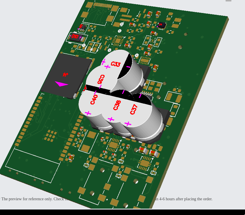
on jlcpcb some components are wrong
in picrel you can see the SHIT i am talking about
>>2936458
idk about jlpcb or any other chink supplier for business
i use those for my private project
but i'm plenty sure boss would rip me another one if I ever put something like that in a product
and if they have certifications and what not theres definately someone who is going to doubt it
idk if they know how NDA work
>had traumatic flashback today
just to add one to the list if what makes embedded so painful
we run the products in the lab alot without the enclosures lid because youre probing and modifying and what not all day anyways so why ever replace the lid
one day we had a fault that bamboozled everyone and also seemed to be sporadic and was impossible to reproduce etc etc.
long story short:
the lid coupled some noise from one location to another fucking things up and all that
just one of those youre chasing the fault for a week and at the end you look very very dumb went through all the datasheets, measured everything, called apllication engineers and so on and someone goes 'huh... if I put the lid on and press down in thos corner it changes, aint that odd? '
Anonymous
8/5/2025, 6:44:15 PM
No.2936500
[Report]
>>2936502
>>2936469
>but i'm plenty sure boss would rip me another one if I ever put something like that in a product
if you ever "put" those intersectinc capacitors?
>idk if they know how NDA work
what do you mean?
btw this is my own project, open source, done entirely be me
hmm maybe you are relpying to the wrong person? idk
Anonymous
8/5/2025, 6:52:21 PM
No.2936502
[Report]
>>2936536
>>2936500
idk this is an imageboard in the style of furaba for a reason but if we wanna (You) alot:
Someone, I suspect (You), was like
>>2936389 (You) #
on jlcpcb some components are wrong
in picrel you can see the SHIT i am talking about
here
>>2936458
and that sort of sounds like they (You) are suggesting for me to use JLPCB or something similar at work.
But placing an order there would probably be the last day I have work because a) that would mean leakimg company secrets and b) that would. also. mean I unironically intend to incorporate items of dubious origin into critical infrastructure which might make the customer (state) a wee bit mad.
Anonymous
8/5/2025, 8:13:41 PM
No.2936514
[Report]
>>2935954
>since you're using a 'puter, you can debounce in software
this is the way. sample on a timer interrupt and debounce/filter inputs.
>wont work if you insist on using interrupts, tho
tying interrupts to real-world noise is a good way to produce interrupt storms
Anonymous
8/5/2025, 8:21:57 PM
No.2936517
[Report]
>>2936520
>>2936469
>idk about jlpcb or any other chink supplier for business
Somehow foxconn's customers get by.
I haven't used jlcpcb yet but I figure I might on a personal project to see how it goes.
Any of you have suggestions for quick-turn fab and assembly shops that will sign an NDA? They don't have to be cheap if they're fast and good.
Anonymous
8/5/2025, 8:50:09 PM
No.2936520
[Report]
>>2936672
>>2936517
for private projects they are good I also can recommend pcbway, excellent speed.
Regarding work I could only name some. that are national / local to me and so most likely of little use to others. It's hit and miss, we had a time at work where every non critical mini-project, time and quality wise, would go out to a different new supplier, only so we could evaluate service, speed, quality etc.
Anonymous
8/5/2025, 11:11:10 PM
No.2936536
[Report]
>>2936458
Thermal reliefs are the gaps in your ground plane around pads that make the pads easier to solder.
I ordered a bunch of RISC-V chips myself, the CH32V series, but I’m too retarded to figure out a toolchain on my frankenstein’d arch install.
>>2936502
No I think the was confused and was assuming you were already using JLC. As for NDAs, I doubt the chinks have time to reverse engineer every damn project you put through them, especially if you don’t tell them to upload the firmware too. But I guess it wouldn’t be a YouTuber sponsorship read without some sort of caveat. Still wouldn’t use them for important production runs, just prototyping.
Anonymous
8/6/2025, 1:25:30 AM
No.2936560
[Report]
First time posting in this board.
Stupid thought went through my head and idk where to post it: What if I made a 68k computer?
OK, I thought for a moment and typed up this
CPU:
>68060 @ 50MHz
Memory:
>2MB Flash ROM
>16MB RAM expandable to 128MB
Video:
>8MB of VRAM
>OpenGL 1.x 3D acceleration?
>Resolutions of up to 1080p
>16.8mil colors
Audio:
>8 stereo PCM hardware channels at 44.1kHz
Storage:
>microSD support
I/O:
>4 USB2 ports
>HDMI ports
Expansion:
>4x 16-bit ISA slots
>2x 32-bit PCI slots
Thoughts?
Anonymous
8/6/2025, 3:50:33 AM
No.2936578
[Report]
>>2936567
24bit colour * 1920 * 1080 = 50Mb = 6.2MB
You probably want at least twice the VRAM for a single framebuffer so you can write to one frame while the other is being displayed. It's a pretty esoteric project in general, I wouldn't even know where to begin. Are you going to design a graphics card?
Anonymous
8/6/2025, 1:17:18 PM
No.2936643
[Report]
>>2936567
>Thoughts?
years worth of effort for little gain
because anything you wanna do with it, you'll have to write the code for it
every tiny little thing
a keyboard routine, with roll-over, which is no easy feat
RS-232 code
video code
audio code
a monitor, editor, assembler, compiler
but before any of that, months of building and debugging the hardware
which is gonna be so slow, even Pong will lag
or you can skip all that BS and go straight to coding applications with a $5 ESP-32 board with 10x the power
Anonymous
8/6/2025, 4:59:55 PM
No.2936671
[Report]
>>2936567
It would be fun if you have no other hobbies and don't plan to have any other hobbies. But what software would you run on it? If you ported a unix, it would just be a slow unix machine.
I've always thought it would be fun to have a really loaded big box Amiga around but I got over it some time when Bill Clinton was still president.
Anonymous
8/6/2025, 5:05:45 PM
No.2936672
[Report]
>>2936703
>>2936520
I've heard of people sending board files out by 5pm friday west coast time and getting boards back from China on Monday. Not for cheap. Not sure if they could get them assembled or how long that would take. Would be nice to have a known good supplier dialed in like that - that's how you hit 2-3 week cadences.
Anonymous
8/6/2025, 8:01:04 PM
No.2936703
[Report]
>>2936709
>>2936672
Yeah I did that a few times in uni. You know. Fuck about with your lab partner all semester, last week for the project: Oh shit oh shit.
PCBway does their thing, meanwhile code shit. Have chatgpt document it all. Done.
Anonymous
8/6/2025, 8:13:07 PM
No.2936709
[Report]
>>2936703
Yeah PCBway is a little lower end than I was thinking but might work. I was thinking who can send by overnight courier for reliable Monday delivery.
Anonymous
8/7/2025, 10:23:06 AM
No.2936836
[Report]
>>2936943
Is it possibleon 328p to configure phase correct PWM in such a way that ONE of the two signals is inverted?
My manual says to set the COMnx1:0 bits to achieve the desired non-inverted or inverted output.
So setting COMAx1:0 to 3 (set if count > ref)
and COMBx1:0 to 2 (clear when count > ref)
should lead to the desired behaviour, right?
Like say BOTTOM was 0, TOP was 1024 and I set both compare regs to 512 I'd get a 50% differential signal?
>>2936836
Me again.
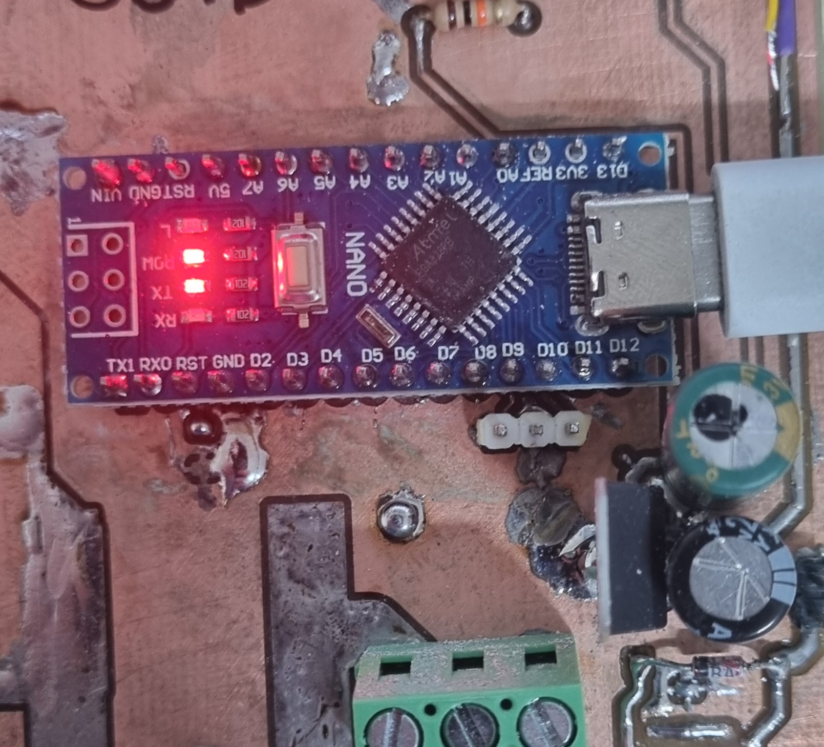
It's a chinese board. Took it out its bag and soldered it straight to board without testing (tested another one from the same batch).
TX light is on. Serial seems gibberish but might be encoding / rate issue.
Upload stuff:
Input/output error
not in sync
resp=0x00
Awesome. Not sure if I can get it off the board also I am absolutely sick of working on this shit. What do? How to nuke the ROM? Anything else im overlooking?
Anonymous
8/7/2025, 10:39:38 PM
No.2936950
[Report]
>>2936960
>>2936943
If you don’t have a USBasp, use an Arduino as ISP, where you program an arduino to be an ICSP programmer that you connect to the 6-pin header on the target you want to program. Then you burn the bootloader. FYI you’ll probably need to add a capacitor from the programming Arduino’s reset pin to ground once it’s programmed.
Anonymous
8/7/2025, 11:23:04 PM
No.2936960
[Report]
>>2936962
>>2936950
its all so tiresome.
USBasp
but another ome from the same batch programmed fine via usb
Anonymous
8/7/2025, 11:40:22 PM
No.2936962
[Report]
>>2936987
>>2936960
same batch
behaves normal
this board got fucked up in no time
it was supposed to be an improvement over the last proto but whatever
Anonymous
8/8/2025, 2:22:31 AM
No.2936987
[Report]
>>2937039
>>2936962
your mistakes were:
>not just putting the mcu and supporting components on the board directly
>trusting chinky arduino clones enough to not test each board first
>not mounting the icsp header
>using hacky usb serial bootloaders in the first place
Anonymous
8/8/2025, 11:05:17 AM
No.2937039
[Report]
>>2937046
>>2936987
well it works now
regarsing the ISP id just solder wires when needed
pls give me a rundown how to use 2 nanos in a fashion where i get around that serial on the underside of the board
Anonymous
8/8/2025, 12:02:10 PM
No.2937046
[Report]
>>2937219
>>2937039
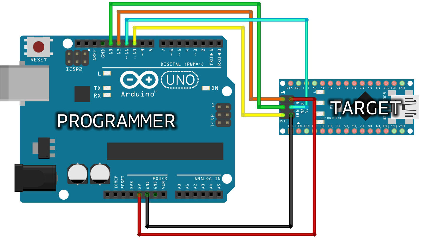
>pls give me a rundown how to use 2 nanos in a fashion where i get around that serial on the underside of the board
Just follow any Arduino as ISP tutorial:
https://docs.arduino.cc/built-in-examples/arduino-isp/ArduinoISP/
Pic especially related. All the same data pins (D10,11,12,13) still go to the ICSP header on the target. The only difference when using a Nano instead of an Uno as the source, is that you probably need a capacitor from the source's reset pin to ground. 1-10uf should be good, only add the cap after you've written the sketch onto the source arduino. If you plan on doing this a lot, I'd recommend soldering a ribbon cable to the host machine with 2x3 IDC connector on it.
The missing IC is the USB-to-serial converter (and the voltage regulator, in case you're running on 7-15VDC input). Without the IC you can't program it via the USB port, or send serial messages over the USB port.
Anonymous
8/9/2025, 6:47:24 AM
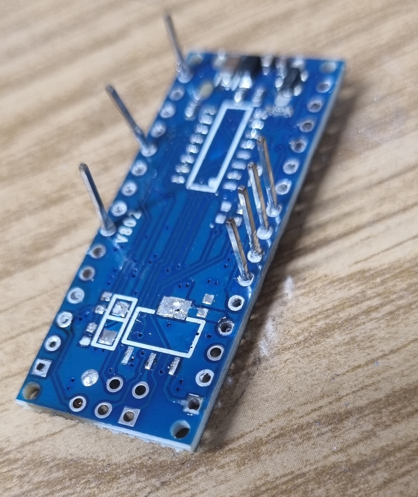
No.2937219
[Report]
>>2937046
I got a lot of boards, uno nano mega due
so. if you say use uno for it ill use uno for it
>missing IC
heh
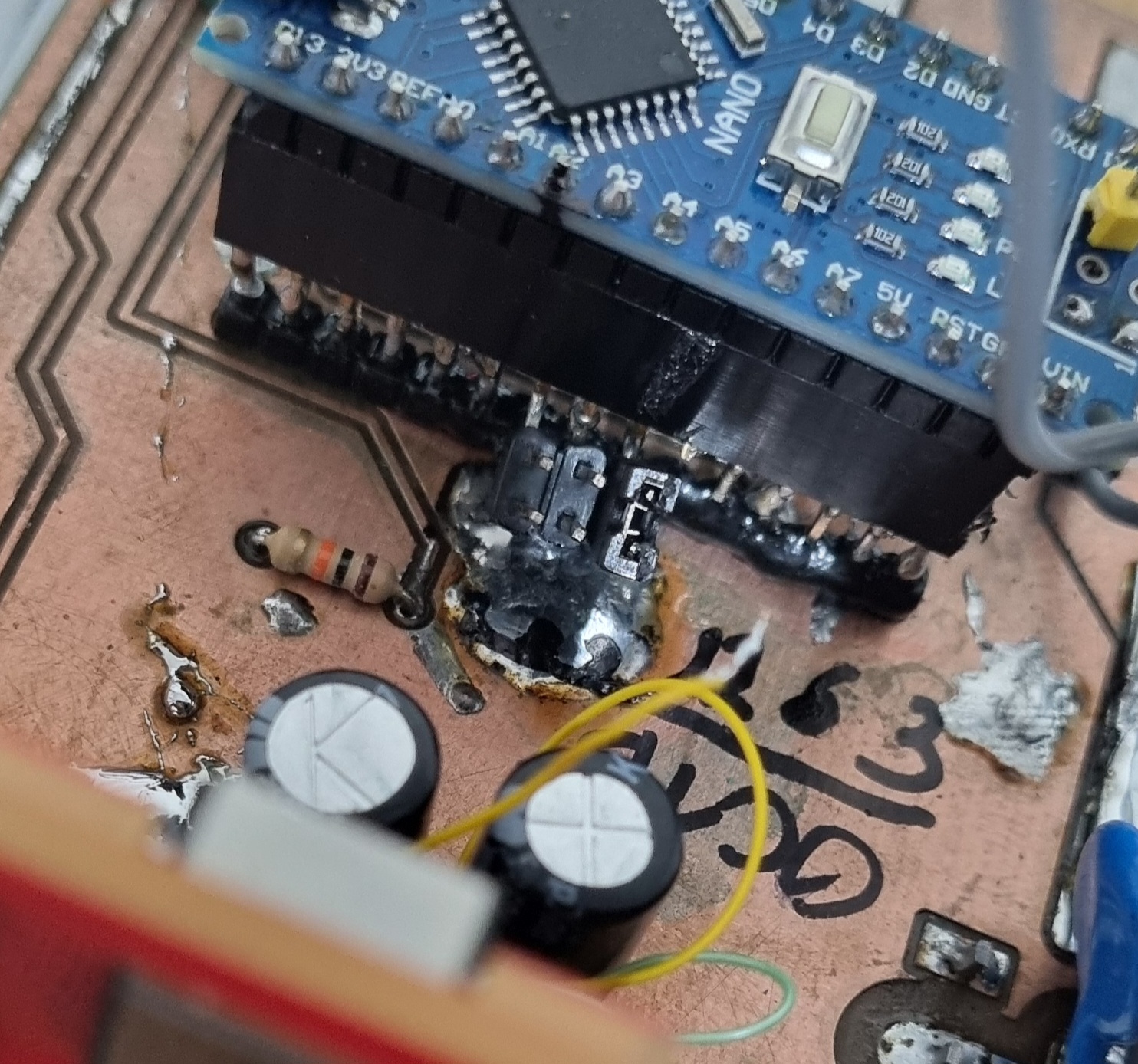
I sure know what a USB serial converter is and what it does. I mean after all thats what you see when you plug an arduino into your computer.
The reason it's 'missing' is because I desolered the whole lot and generally speaking desoldering things with many pins and lots of masse with just iron and air leads to things like picrel. At least you get a free ch340 and linear reg. Would probably cost more than a chink nano if you bought them like that.
Anonymous
8/12/2025, 11:07:16 PM
No.2937938
[Report]
>>2937956
>>2937981
Hiya!
So I have a 328p on a board and it functions as a source for PWM, either phase correct or up counting depending on mode of operation.
My development process requires me to gradually hike the PWM up after making changes to a board, because an unpredicted element or any error and the whole thing will break.
I can also not allow glitches here. It's a high EMI environment once the PWM is on.
Low or zero value PWM is inconsequential. Accidentially high duty is bad.
I want to hack something on to my board that lets me speed this up without having to reprogram.
My thoughts how to do this are as follows:
I will run code to adjust the PWM once in the setup() function and not update it during runtime. This is to make sure EMI does not fuck with the reading. I will place a row of jumpers that encode the desired setting. The jumpers will pull down as to defeat EMI and loose jumpers. A jumper being placed leads to the duty to increase. So again: This is meant to lead to a safe design, where a loose or forgotten jumper is not catastrophic.
I have plenty of open pins on the board.
So assuming I want 8 bit resolution I plan to reserve 8 pins (17, 18, [22,26], 28) for this, first set them to input, active pullup, delay, and then read each pin and shift it into a byte. When done pass this byte to the register like OCR1A.
Then main empty while(1)
What could go wrong? Is there a better way to do this? I want discrete steps and a low impedance environment. Again: I think a pot is too risky. I might even make entire 8 bit jumpers and key and mark them as to not make mistakes.
>>2937938
>those pins
I’m not sure what pinout chip you’re using, but shouldn’t it be a full port? Like PB0-7 or PC0-7. That way it’s trivial to read all the pins at once e with a port read, and just save that to the timer/counter register. But I’d ensure your reset button/switch is actively pulling to a rail in normal operation, and only being pulled weakly via resistor when it is being reset. I assume all output pins turn hi-Z when reset is a logical high.
Instead of jumpers you could use a pair of hexadecimal rotary selectors.
For safety I’d tie LEDs to the jumpers/switches so you know they are in the right state when you toggle them. Or even better, have the MCU spit out the jumper setting somehow and ask you to confirm before it goes into the main loop. It could confirm with parallel LEDs, or with a digital output to a computer (galvanically isolate your signal), or to an I2C screen if you want. You could even just set the PWM value by comms from a computer and do confirmation the same way right afterwards. Ethernet comes to mind as it’s inherently isolated at both ends, but do whatever.
You’re the EDM anon aren’t you?
>>2937956
I'm thinking a bit like this:
void setup() {
int pinsInputPullup[] = {17, 18, 22, 23, 24, 25, 26, 28};
for(int a = 0; a < sizeof(pinsInputPullup)/sizeof(int); a++){
pinMode(pinsInputPullup[a], INPUT_PULLUP);
}
char A = 0b00000000;
for(int a = 0; a < sizeof(pinsInputPullup)/sizeof(int); a++){
A &= digitalRead(a);
A << 1;
...
OCR1A = A;
}
>>2937956
>but shouldn’t it be a full port?
Luckily I'm dealing with an MCU and not some ASIC here. So I get to do whatever I want in the software, right? And the thing is on the board now and some lines taken. Why 'should' it be a port? I get it's convenient and saves a few cycles KEK. This runs once and the ALU idles after setting up its PWM.
>use a pair of hexadecimal rotary selectors
I dont have any. Also why hex?
>have the MCU spit out the jumper setting somehow and ask you to confirm before it goes into the main loop
I should also note that there is a requirement where this gets done today and doesnt consume any amount of ressources, as such there will be no shopping and not much effort.
>galvanically isolate your signal
Same issue: No transformers. Optos might be too slow for serial but too much effort and potential pitfalls anyways.
>set the PWM value by comms from a computer
the lack of isolation is why I am currently stuck in a cycle of unplug MCU, take to desk, upload config, plug back in. The very cycle I'm looking to speed up.
>Ethernet
See above. It's obviously a nano. Not writing and debugging drivers that abuse an ethernet port in such a ways today. I should mention my programming sucks and is slow.
>You’re the EDM anon
You're the EDM curious anon. Latest purely qualitative measurements imply we do now have bipolar behaviour. KEK. It's not intentional but rn it looks like that. And the measurements check out when compared to each other. Obviously the voltage on the output side can only remain the same if no charge leaves through the gap or go up if charge is transferred into the output ...
Anonymous
8/13/2025, 12:21:54 AM
No.2937963
[Report]
>>2937995
>>2937956
>>2937962
...
The output does exactly that. Dampened oscillation for ~ 3 periods during the discharge. The current waveform or first derivative thereof mirrors that.
I wonder where that comes from. With the last board I sometimes felt like it's trying to do that. But there was no inflection points, not even real saddle points. Now since the inductor has a core (but same inductance), the power is up by quite a bit and the coupling cap is several times greater. I suspect one of those changes did that.
Only remaining question is: Is that really beneficial, or not and what's exactly going on.
Anonymous
8/13/2025, 12:27:51 AM
No.2937964
[Report]
>>2937981
>>2937962
Just assume I put the ~ there to account for the pullup logic
>inb4
>wanted to create a simple remote control
>chatgpt told me to get an STM32 Nucleo and CC1101 RF module
>ok done
>ask it to walk me through setting up a simple blink program to get going
>need to create 4 different files with hundreds of lines
what the fuck did i get myself into? i dont remember arduino being this difficult
Anonymous
8/13/2025, 2:04:23 AM
No.2937981
[Report]
>>2937983
>>2937938
SHIT! There only really is 3 pins on that side. Well I guess its going to be a 3 bit setting.
Cant be fucked. After all thats 9 power levels and if something is wrong I get to see that on the first, generally.
Also
>>2937964
not ~
its !.
Like I said my programming sucks.
Anonymous
8/13/2025, 2:13:58 AM
No.2937983
[Report]
>>2937987
>>2937981
int pinsInputPullup[] = { 17, 18, 19};
for(int j = 0; j < sizeof(pinsInputPullup)/sizeof(int); j++){
pinMode(pinsInputPullup[j], INPUT_PULLUP);
}
uint8_t A = 0;
for(int i = 0; i < sizeof(pinsInputPullup)/sizeof(int); i++){
A &= ~(digitalRead(i));
A <<= 1;
}
What am I doing wrong? It looks like pins 18 & 19 come back 0. I've confirmed they are all being pulled up.
Anonymous
8/13/2025, 2:36:16 AM
No.2937987
[Report]
>>2937983
Solved.
>my programming sucks
mistakes were made.
Naturally I wanted to
A |= digitalRead(pinsInputPullup[i]);
Also A<<1 on top of the loop as it doesnt hurt on the first time but would double the result on the last round when it's at the bottom.
Now, with 2 random leads shorted to GND, it goes:
00000000
00000001
00000011
nice.
>>2937962
>Why 'should' it be a port?
Because it tickles my autism, and makes it easier not to program it wrong. Which might be pretty useful judging by the subsequent replies. But your method is more free to the rearranging of pins, so I guess you’re not making a new circuit layout and are somehow using existing pins to add these jumpers?
>why hex?
Because an 8-bit binary number is the same as a 2-digit hexadecimal number. With 8 pins you get the full 256 different combinations. Decimal selector switches on 4 wires each would only give you 100 combinations, plus you’d need to do the decimal-to-binary division.
>Optos might be too slow for serial
Just use a slower baud rate. Or even just flash a single LED at the set duty-cycle and measure it with a photodiode (read: another LED) and your oscilloscope, or even just look at the brightness with your eye. That will be enough to avoid sudden increases of duty-cycle.
>bipolar
Is the voltage going low enough to get a spark jumping in the opposite direction? Hmm, maybe going without the capacitor is the way forwards…
Also you’ve successfully convinced me that ECM is the better way to go if I just want subtractive machining of metal parts on the cheap. That still needs reverse feed-rates for short-mitigation though, so I’m waiting to see what your sucky coding (your words not mine) can do about that.
>>2937963
Mutual capacitance to the inductor core? What core material are you using anyhow?
>>2937977
Shoulda used an ASIC, like an HT12E.
>>2937995
It aint pretty but it works. That goes for the hard- aswell as the software.
We had a little explosion along the wax and half the time went into fixing that.
Guess I shouldn't always use the transformer soldering gun.
Works as advertised. Placing the jumper adds time to the on period as youd expect from binary, 1T, 2T and 4T or combinations of those.
>the explosion
I always thought those glass diodes were nothing but MELFs on a stick? And I thought the appeal with MELFs is the deterministic failure mode? Anyways I had a glass diode go short. B170 or whatevs I just used any. It blew a trace under a cap, what a bitch to find and fix it was.
Anonymous
8/13/2025, 3:56:10 AM
No.2938000
[Report]
>>2938003
>>2937999
fun time debugging this shit
Anonymous
8/13/2025, 4:23:37 AM
No.2938003
[Report]
>>2938007
>>2937999
That's why you should always route pads for each of the unused GPIO pins, at least whenever there's room. Some spare GND and VCC too, though in this case GND is covered for you. You never know when you're gonna need extra pins.
Also not liking that solder blob bridging that trace on the left there.
>>2938000
Brutal, what caused the diode to blow?
Anonymous
8/13/2025, 4:46:10 AM
No.2938007
[Report]
>>2938003
Well I spilled a whole lot of solder across the entire board. It fell off the tip. So I used a big glob of flux and flowed everything out, so I thought. Must have forgotten a few spots. So just a random short on the power for the DC-DC, not the high power section but not the digital either. I think that's literally the best outcome. On the high power section god knows how big the hole would have been, on the digital it would have gotten the regulators and such, maybe. The DC-DC power: Just that diode that I thought would fail open beyond 1A but it failed short.
>Pads for extra stuff. Yeah good idea but then again soldering gun goes brrrrr.
>not liking sold... - ACK
soldering gun goes BRRRRRRRRR
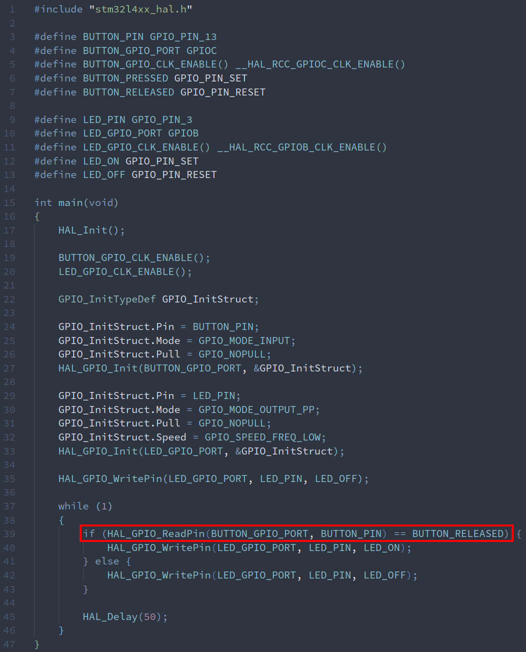
>>2937977
Can someone explain this shit? Pic related works as expected; LED is on when button is released, and turns off when button is pressed.
When I invert the highlighted if to say != BUTTON_RELEASED, the LED just stays off regardless of the button being pressed/released. What the fuck?
>>2937995
>Shoulda used an ASIC, like an HT12E.
I don't even understand how to use that. My goal is a programmable 318MHz remote control to open a garage door.
Anonymous
8/13/2025, 5:57:41 AM
No.2938013
[Report]
>>2938015
>>2938012
Oh. The button electrically shorts the LED to ground when it's pressed. Why the fuck
Anonymous
8/13/2025, 5:57:46 AM
No.2938014
[Report]
>>2938078
>>2938012
Well what happens if you yet it to equal and stick the negation onto button released?
But I guess it wont work. You'll probably have to look into how button released works internally.
Anonymous
8/13/2025, 5:58:47 AM
No.2938015
[Report]
>>2938078
>>2938013
LMAOOOO
better safe than sorry huh
Are there only enthusiasts here or there are actually people who work as embedded developers?
Anonymous
8/13/2025, 1:07:39 PM
No.2938054
[Report]
>>2938098
>>2938050
>here are actually people who work as embedded developers?
Yes.
>>2938012
There were other weird issues where my code wouldn't flash and I had to unplug & replug the dev board for whatever reason(took me way too long to figure out). But I've got a good starting point now: I put the dev board on a breadboard with a button and LED, and all works as expected. Plus, I set up UART for bidirectional serial console communication so I can actually debug shit and send commands to the board without wiring up a bunch of buttons. Working on the CC1101 but crimping duponts is a pain in the fucking ass so I'm waiting for the female to male jumpers I ordered.
Does anyone know if there's an "adapter board" for a 2x4 pin layout to a 1x8 breadboard-compatible layout so I have something a little more rigid?
Thanks for reading my blog posts!
>>2938014
>>2938015
Turns out that button is a RESET, it's only labeled B1 on the board for whatever reason.
>>2938050
>there are actually people who work
lol
lmao
Anonymous
8/13/2025, 8:39:58 PM
No.2938098
[Report]
>>2938054
did until spring this year
no one on the team had a very specific position like 'embedded' developer. Everykne was just development engineer and the tasks reflected that. I mean we had guys who werw more or less on one or another side of things and they'd do the respective tasks. But in reality when you're responsible for a few products you get all sorts of work, some hw, some fw, some sw, general design and integration and testing things, compliance and what not.
Anonymous
8/13/2025, 10:02:13 PM
No.2938112
[Report]
>>2938134
>>2938050
I'm not working for much longer lmao
Anonymous
8/13/2025, 10:56:03 PM
No.2938120
[Report]
>>2938121
>>2938078
>I set up UART for bidirectional serial console communication so I can actually debug shit
You’re using a nucleo board, its built-in programmer is also a debugger that can pause the MCU and read out its registers, use GDB for this if you want proper cycle-by-cycle debugging.
Anonymous
8/13/2025, 11:02:38 PM
No.2938121
[Report]
>>2938120
>its built-in programmer is also a debugger that can pause the MCU and read out its registers, use GDB for this if you want proper cycle-by-cycle debugging.
Thank you! That's great to know.
Anonymous
8/14/2025, 1:14:33 AM
No.2938134
[Report]
>>2938112
You're just feeding them while they can't stop laughing and assume you're literally retarded because no mstter how many times they fuck you over you still support them.
Anonymous
8/14/2025, 2:04:22 AM
No.2938138
[Report]
>>2938078
>CC1101
Can't get it working. I can initialize it and put it in RX mode, but it just picks up constant garbage instead of an actual signal.
Using CC1101_ReadStatusReg (with 0x30-0x3B addresses):
PARTNUM (0x30): 0x00
VERSION (0x31): 0x14
MARCSTATE (0x35): 0x01
RXBYTES (0x3B): 0x00
TXBYTES (0x3A): 0x00
Configuration registers:
FREQ2/1/0: 0x0C 0x2E 0x8B
Anonymous
8/16/2025, 2:54:21 AM
No.2938447
[Report]
>>2938463
>>2937999
I’ve been thinking about a bootleg reverse g-code alternative for clearing short-circuits. If a short is detected by a comparator or whatever, an arduino could then pull a pin low to tell the mainboard to halt it’s g-code execution, and another pin to stop the EDM machine from pulsing. Then the MCU would send its own step/dir commands to the Z driver to move upwards, until the short is cleared. Then it would move downwards either until it reaches its original position or until it detects a short again and has to move upwards. When it’s moving up the EDM pulser is disabled, when it’s moving down the EDM pulser is enabled. Once it gets back to its old position with no shorts, the pin goes high again and the mainboard resumes g-code execution.
I was reading a GitHub post and the guy was saying you want variable feed-rate with feedback to your spark voltage, for ECM I guess you could do the same, but I don’t believe Marlin or GRBL have the capability to do adaptive feed-rates. Maybe LinuxCNC can. I think GRBL can do g-code halting, I suspect Marlin can too but I’ll have to look into it.
Anonymous
8/16/2025, 6:32:15 AM
No.2938463
[Report]
>>2938466
>>2938447
What you described neither needs G-Code, GRBL, a stepper controler, steppers or any of all that since you're describing a ome axis machine 'sinker EDM' or 'ram' where the reversal of movement is trivial. If it's working in the - Z direction reversing to clear shorts means +Z.
>variable feed rate
Yes you can do that. Especially since that is a very common feature on all sorts of CNC machines, where the UI often includes a rotary encoder or pot that can be used to overwrite speeds and feeds.
But the case where this actually is non-trivial, idk if it was ITT, an earlier one or an entirely different one, but I have alluded to that before, is 2D movement, like it is commonly associated with WEDM or any other EDM process that actually requires a toolpath. Suddenly clearing a short is non-trivial and requires at least understanding of the current movement vector at the time of the short occurring or actual memory of the toolpath leading up to the short.
Luckily this has been solved by Roland of the G-EDM project, who rewrote GRBL do do exactly that.
Anonymous
8/16/2025, 6:49:36 AM
No.2938466
[Report]
>>2938469
>>2938463
My suggestion would still work fine for side-milling so long as the tool has no concave geometry. Not for a slitting saw, but yes for an end-mill. Sure it would be inefficient to go all the way up out of a deep cut to clear a short instead of just backing off a quarter mm, but it should work. Hope it wouldn’t get caught on the way down again.
>Yes you can do that. Especially since that is a very common feature on all sorts of CNC machines, where the UI often includes a rotary encoder or pot that can be used to overwrite speeds and feeds
No I mean adaptive speed changes, where the machine detects the load on the cutting bit and adjusts the speed accordingly via some sort of feedback loop.
>G-EDM project
Oh I should look into that.
Anonymous
8/16/2025, 7:10:49 AM
No.2938469
[Report]
>>2938480
>>2938466
I don't think you're getting what I wrote. It is a standard feature on NC controllers to have an input for adjusting speeds and feeds on the fly. The input is a defined interface, it does not care if an actual rotary encoder or pot is connected to it, only that whatever is connected to it acts or looks like it and thus conforms to the interface.
>>2938469
>The input is a defined interface, it does not care if an actual rotary encoder or pot is connected to it
Ah, I see what you're saying. I assumed there'd be a separate input for a manual control compared to an automatic control. Because the automatic control is part of a feedback loop, it should increase the feed-rate until the voltage passes a threshold. If it's just expecting a potentiometer then you'd need an external error amplifier, which is ok, but then if you also want to be able to automatically set a different voltage threshold for roughing and finishing passes you need a DAC. Anyhow, does GRBL or Marlin do that?
Hope that GEDM project will be applicable to ECM.
Anonymous
8/16/2025, 4:50:29 PM
No.2938531
[Report]
>>2938654
>>2938480
>>2938480
I omdont want to offend but I think you're a bit all over the place with your thoughts and also more concerned with what could be done instead of what is sensible to do.
Like having two MCUs and have one take control from the other and hand it back without having a real interface and protocol for that... it doesnt make too much sense.
Meanwhile the speed overwrite input: It's just that. Input that overwrites speeds. And its got a nice interface, you know, voltage, or pulses.
>you need a DAC
you never really 'need' anything digital. Yes there's reasons why we like to do things digital and avoid analog as much and as long as we can.
Also switch that either puts another R in series or parallel with that signal source or biases it by various means if one really insisted on jogger rigging something like that onto a preexisting input of that kind.
>Does controller firmware do that
Yes absolutely. Besides the fact that you can always write a simple M code, marlin for example is already equipped out of the box to toggle a digital pin on any board that you have a HAL for.
But if you ask me: Just use the S parameter? I dont expect you to have an actually rotating spindle. And your gap voltage is probably the best analog. So instead of not using the S parameter at all just define it as an proportional to gap voltage. If you insist on a hacky solution feed a diff amp of that and the gap voltage into the speed overwrite? Tada theres your thing.
Anonymous
8/17/2025, 12:55:06 AM
No.2938654
[Report]
>>2938531
>I think you're a bit all over the place with your thoughts and also more concerned with what could be done instead of what is sensible to do
I’m just spitballing for now, trying to see what is doable, then narrowing that down to what’s sensible, then narrowing that down into something I should make. My aim is <0.1mm accurate parts made of metal for cheaper and quicker than getting them milled or 3D printed overseas. Wire and sinker processes are useful for specialised geometries, but I’m just after bulk roughing out of billet, so a square-nose cylindrical end-mill is probably the way to go for me. EDM seems both more difficult/expensive to make, while being slower and more prone to tool wear.
>S
Ahh, that’s a very nice elegant method with a pulse frequency output that’s easy to turn into a DC voltage. If I have to use Marlin or GRBL it’s worth keeping in mind.
But that G-EDM project looks promising enough I probably won’t have to use stock GRBL or Marlin, and I think I have all the stuff lying about to get it working, sans the screen. Wish it had better documentation, but it’s a relatively new project so we’ll see.
Anonymous
8/21/2025, 7:00:07 PM
No.2939743
[Report]
>>2939771
Is there any way to use the counters in a 328p so that there is an output that is centrally aligned to an edge of the other output?
Like imagine one output toggles but just before every falling edge the other output turned 1 and back to zero after the falking edge. So it's like the phase of one outpur was aligned to the edge of the other.
Anonymous
8/21/2025, 10:18:17 PM
No.2939771
[Report]
>>2939775
>>2939743
Maybe if you could use a single timer with one compare channel in phase-correct-PWM mode and the other output toggle-on-rollover mode, but I suspect you cant have two different waveform outputs in a single timer. Worst case you just synchronise two timers I guess. There’s probably a smart way of synchronising timers with interrupts but I never tried.
Anonymous
8/21/2025, 10:34:00 PM
No.2939775
[Report]
>>2939848
>>2939771
I think I have now settled on just cycle counting and probably hard coding a few modes. The thing is I dont need anything besides the setup and then the timers. So for the time being I can just keep cycle counting indefinately without ever handing over or overly complex flow.
And afaik... idk 4 cycles for a noop? I think it was something lile that, I need microseconds so that should be well within reach and precise to some digits too.
>inb4
yes single micros not multiples of 4 plus minus
Anonymous
8/22/2025, 3:01:24 AM
No.2939848
[Report]
>>2939942
>>2939775
I would have just delayed the other output (assuming trailing edge) and sent the output through a pulse stretcher using some discrete logic.
Helps if you have access to a 2x freq clock.
Anonymous
8/22/2025, 4:39:13 PM
No.2939942
[Report]
>>2939954
>>2939848
the board is as is I can only change software at this point.
>which is better:
i could make a simple blocking delay function that takes one argument, uS, multiplies it and loops through as many noops and call this at several points in an eternal loop
Alternatively I could reset a timer and block using a while(timer register < xxx) {}
and reset the time every time
that way it wont ever overflow and I dont need to add previous elapsed time
Which method to prefer and why?
I'm bad at programming and I think I'm experiencing paralysis by analysis
>>2939942
Is, in the arduino environment, this
void loop() { do stuff}
any different from
void loop() {while(1){do stuff)}}
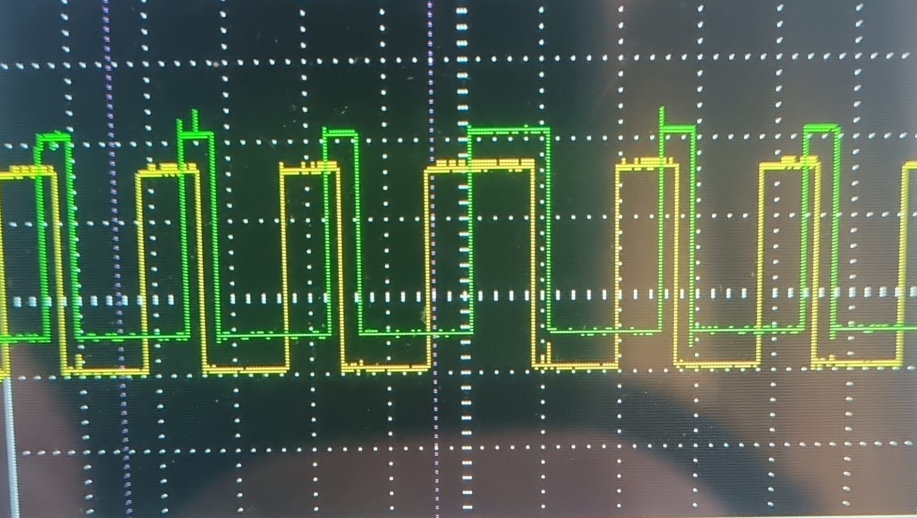
?
I have just written my stuff using delayMicroseconds which is bad as it again has a resolution of maybe 4 uS but i wanted to get out of paralysis quick
I've then caught a glitch. See picrel.
I was concerned over arduino related stuff like watchdogs or similar fucking my shit up.
So I tried while(1) to prevent it from ever handibg back and I havent been able to catch another glitch which doesnt mean there is none.
Glitches would be bad.
Anonymous
8/22/2025, 7:01:11 PM
No.2939974
[Report]
>>2940007
>>2939954
I'm now also thinking:
no interrupts might be a good idea anyways but also:
Is there anything in an otherwise empty 'sketch' that could trigger interrupts
Anonymous
8/22/2025, 7:50:46 PM
No.2939985
[Report]
schematics for burst emitters ?
jammers also plox
Anonymous
8/22/2025, 9:29:44 PM
No.2940007
[Report]
>>2939974
This seems to work oksi
[code]
void microsecondsDelay(uint8_t uS) {
uint8_t count = uS * clockCyclesPerMicrosecond() / 4;
uint8_t i;
for(i =0; i<count; i++){
asm volatile ("nop\n\t"); }
};
[/code]
[code]
PORTB = 0b00000000; //Idle
microsecondsDelay(1);
PORTB = 0b00000010; //Charge
microsecondsDelay(1);
PORTB = 0b00000110; //Connect gap
microsecondsDelay(1);
PORTB = 0b00000100; //Discharge through connected gap
microsecondsDelay(1);
[/code]
I figure a nop is 1 cycle but the loop itself is more like 4 cycles because the incrementing and comparing and all that? idk? is it? it looks kinda good and I'm just going with the inaccuracy as long as I get the precission.
Like yeah sure figuring out count every time takes some cycles too.
Anonymous
8/23/2025, 2:14:22 AM
No.2940048
[Report]
>>2940127
>>2939954
> glitch
Interrupts disabled?
Anonymous
8/23/2025, 2:58:04 AM
No.2940051
[Report]
>ardushitto
>>2940048
Yes I have disabled interrupts for the critical part. I'm curious regardless, suppose you did not, what is there in an otherwise blank 'sketch', when n there is no comms and nothing, to trigger interrupts?
Anonymous
8/23/2025, 10:48:44 PM
No.2940219
[Report]
>>2940226
>>2940127
The USB serial bootloader
Anonymous
8/23/2025, 11:27:44 PM
No.2940226
[Report]
>>2940240
>>2940219
wouldnt that onyl trigger shit when comms are happening?
Anonymous
8/24/2025, 1:24:28 AM
No.2940240
[Report]
>>2940242
>>2940226
Only happens at boot / power-on-reset, regardless of whether there's serial comms, not sure if there's actually an interrupt going on but it sounds likely.
Anonymous
8/24/2025, 1:32:50 AM
No.2940242
[Report]
>>2940245
>>2940240
Mhm shitty situation, since I need to be sure and I have nothing to trigger on pulse length x
id have to make a counter
Anonymous
8/24/2025, 1:36:04 AM
No.2940245
[Report]
>>2940354
>>2940242
it's only there on the boot period anyhow
if you're worried just wipe the bootloader and use an icsp programmer instead, bootloaders were a mistake anyhow
Anonymous
8/24/2025, 12:31:26 PM
No.2940349
[Report]
>>2940127
You wouldn't have to ask this if you didn't use arduinos ridiculously shitty framework.
Anonymous
8/24/2025, 12:47:09 PM
No.2940354
[Report]
>>2940479
>>2940245
nah thats ok first thing I do is bring everything to a safe state
then set everything up
and only before entering the loop all safeties come off
the one I caught did occurr in the main loop
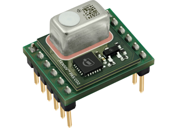
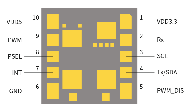
>>2928655 (OP)
hello mcg, stupid question since i am new to this.
how are chips attached to eval boards like picrel? does it have to be soldered if you want it to stay fixed in place?
if the latter, could you not just solder on some wires yourself and skip the eval board altogether?
i have the chip, but not the board.
https://www.mouser.com/new/infineon/infineon-xensiv-pas-co2-5v-eval-board/
Anonymous
8/25/2025, 12:01:36 AM
No.2940479
[Report]
>>2940490
>>2941373
>>2940354
There might be other interrupts coming from arduino functions though, like analogRead, delay, or serialPrint. You should avoid these and directly address the registers if you're unsure.
>>2940438
What do you mean by "chip"? The IC? The metal can? Or the surface-mounted BGA(?) board that contains the IC and the metal can? The lower board that the surface-mounted board sits on looks to just be a breakout board for prototyping, so you should be able to do without that.
Anonymous
8/25/2025, 12:36:29 AM
No.2940490
[Report]
>>2941373
>>2940479
I did not use any of those and only used direct port manipulation and register read writes. Idk how to use all that I only work with the 328p and AVR reference. Thanks for the heads up, all spunds like I expected.
>>2940438
You have many options. In production, if all the products are configured the same, it is not uncommon to solder directly. So either you have 1mm holes for the 0.64mm pins and mount it THT or you can even save yourself the pin headers and aolder vias to vias directly. Depends on if and what there is on the underside and if you can have a cutout in the board etc.
It's also possible sometimes to mill the contour of a board like that so the outer vias are disected. You then have really nice exposed features to solder SMD style.
You can ofc always mount a female header of varying quality or use ribbon cables. This depends on space, the need for customization or replaceability, shock and vibration rating, current rating and RF performance. You can sometimes run two grounded pins on either side of your RF pins, it sometimes helps.
Anonymous
8/26/2025, 5:11:47 PM
No.2940941
[Report]
>>2940944
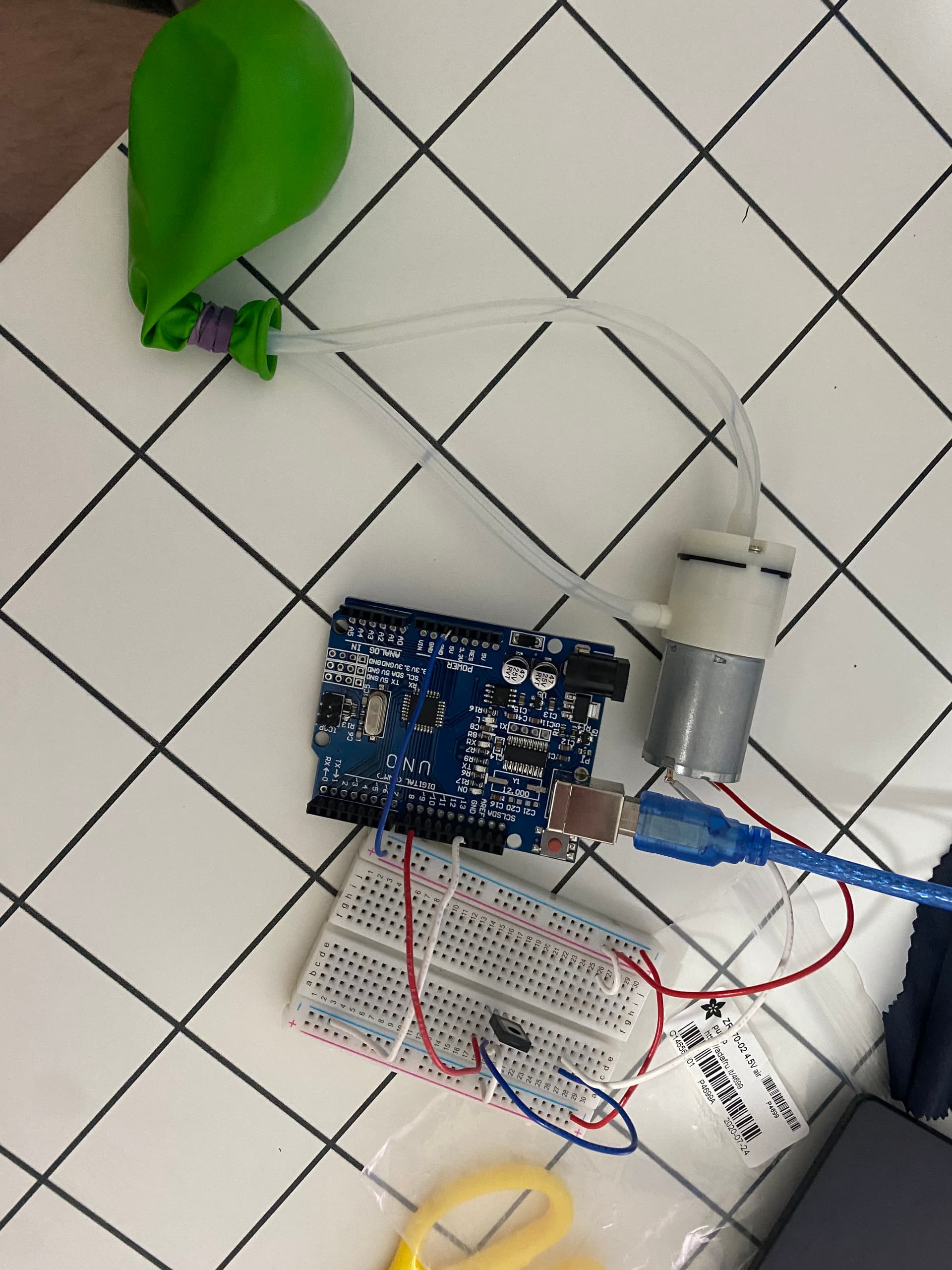
Alright MCG I am reusing a vacuum pump that has an air pressure sensor and a mini dc pump (yb370) I originally used it to vacuum seal filament bags, and SMT pick up tool once in a while, however I wanted to make some changes to work with a foot pedal and a solenoid.
What I have got right now is a 5A pwm controller that has a resettable fuse.
>https://www.amazon.com/dp/B091SHPR6L
2v025 solenoid 12v
>https://www.aliexpress.us/item/3256805024070436.html
air pressure sensor hp203n (reused)
arduino nano
OLED screen
lm2596 or mp1854n 12v -> 5v for motor and nano usb powered
logic level shifter for hp203n operates at 3.3v
Now my question is, how should the motor behave? Should I just have it continuously running even when air flow is block (picking up smd chip with blunt needle) or would I want the motor to stop when it reaches a certain negative pressure, and turn back on when it loses *insert epsilon value* kpa/pa?
To me it seems option 1 would wear the motor out or ruin the motor while at the same time maybe not, while option 2 also seems like it would ruin the motor and the reason for that is because the pneumatic connectors I currently have suck apparently since I cant hold a seal when suing any of them.
pic not mine just found online.
Anonymous
8/26/2025, 5:22:56 PM
No.2940944
[Report]
>>2940950
>>2940941
just run its what units sold as lab equipment do to
and it makes sense
vacuum pumps are designed to reach a certain vacuum at which the lack of gas to pump will automatically let them shed load. Usually mmvacuum pumps are rated to run under those conditions indefinately. You see unlike a pump providing positive pressure vaccuum has a limit and the work doesnt get harder, it gets easier.
Anonymous
8/26/2025, 5:34:42 PM
No.2940950
[Report]
>>2940956
>>2940944
>vacuum pumps are designed to reach a certain vacuum at which the lack of gas to pump will automatically let them shed load.
When I powered the motor directly it was 5v @ 0.7a this probably explains when it dropped to 5v @ 0.4a when I blocked the tube.
the pwm controller seems to have limited the current to 50ma and would shoot up to 200ma when I blocked the tubing, I guess I would just discard using the pwm controller and just power it @ 5v then?
Anonymous
8/26/2025, 5:59:29 PM
No.2940956
[Report]
>>2941020
>>2940950
Yeah, vacuum pumps (and your household vacuum cleaner) use less current when blocked.
But a pump like in picrel is not long for this world, so you want to minimize the on time, and also minimize heat buildup.
Anonymous
8/26/2025, 10:48:52 PM
No.2941020
[Report]
>>2940956
Well from your comment and the other one, it sounds like I should just grab the old pcb that was controlling it, and modify what I can, the manufacturer didnt put any markings on the main IC, and it a pain in the ass so many of the pins are on ground, some pins I manage to figure out but damn I wish I could look up IC by pin placement, and ic-type or whatever ssop and others like that are called.
Anyways thanks, I was hoping to power this from a power supply but I cant seem to find out if this non used solder points P+ and P- are meant for another version of the vacuum pump that can be directly powered from a power supply, but I guess I will find out.
Anonymous
8/27/2025, 10:20:44 PM
No.2941253
[Report]
>>2945394
>>2935852
just get a j-link edu, if you only use it from your private network.
Olimex also has a cheap open-ocd debugger.
Anonymous
8/28/2025, 9:03:58 AM
No.2941367
[Report]
i want to turn wireless debugging on to use Shizuku on my Android phone WITHOUT using any wi-fi connection ("wireless debugging" requires this and i can't find any way to bypass this without root and i don't want to root rn) or any device to set up a local hotspot.
apparently, this isn't possible, so the next best option is to get a the smallest, most portable router for a local hotspot.
is this $4 USB pocket wifi modem i intend to use unSIMmed the best option or could i get a cheaper microcontroller to program a start/stop local hotspot routine?
>second phone
don't have one.
>captcha: KMSWR
Anonymous
8/28/2025, 9:56:47 AM
No.2941373
[Report]
>>2941476
>>2940479
>>2940490
late reply, sorry
>surface-mounted board that contains the IC and the metal can
this sounds about right
picrel is the underside (14 mm wide)
if i buy the breakout board, would i *have* to surface solder the "chip" for it to remain in place? would it be viable with some jank alternative like electrical tape to make it not fall off? rigidness is not too important.
i only have breadboards, so option 2 would entail soldering free wires directly onto the "chip" which then go to the breadboard. but that sounds risky given the size. will an inexperienced solderer not just mess that up and damage the sensor?
Anonymous
8/28/2025, 10:14:29 PM
No.2941476
[Report]
>>2941506
>>2952151
>>2941373
Pressure-based mounting might work if each pad was connected to with something compliant (e.g. pogo-pins), but just taping down one board onto some other surface, even with solder bumps, likely isn’t going to work at all, at least not reliably. Soldering wires onto the pads is the other option, but if you tug on the wires it might rip pads off, and the pinout doesn’t seem to describe what those central pads are for.
Have you already bought the module without the breakout board?
Anonymous
8/29/2025, 1:09:20 AM
No.2941506
[Report]
>>2941476
>Have you already bought the module without the breakout board?
yes. i made a mistake
>Pressure-based mounting might work if each pad was connected to with something compliant (e.g. pogo-pins)
seems unlikely to be the case here, so i think wire soldering is the best option then. i'll probably do it with some female dupont headers. thanks
getting this thing to work will be an excuse to get into soldering, i don't mind desu
I'm a software engineer but just finished an arduino course and now want to build a digital wrist watch. I'm trying to pick out hardware, and the Cortex M0 looks promising as a core. I've narrowed the MCU down to either STM32L0 or TI's MSPM0L (both ultra low power devices). I'm slightly preferring the TI because it's smaller (I'd eventually like to minitiarize the watch as much as possible), newer (although this might be a bad thing), and looks like it has better docs (STM's website is a mess but maybe I'm just too stupid to navigate websites properly). Additionally, as a software guy who's completely comfortable working with code/bits/memory/etc, I found the "hand-holding" of Arduino IDE a bit patronizing, and it seems like there's lot of that in the STM32 ecosystem (although I'm sure there's ways to cut through all that). Would choosing the TI chip be retarded? ChatGPT is pretty strongly pushing me to the STM32; not sure if that's actually the best choice or just the midwit consensus from the internet hivemind.
Anonymous
8/29/2025, 2:22:04 AM
No.2941527
[Report]
>>2941567
>>2941507
do you really need a 32-bit chip for a wristwatch?
it's not a smartwatch, is it?
an msp430 might be a smarter choice
the stm32 ecosystem is wide, if you learn one stm32 then that's a skill you can apply to a lot of different parts for different applications, but yeah people do have some opinions about their bloated hal
Anonymous
8/29/2025, 2:33:28 AM
No.2941529
[Report]
>>2941567
>>2941507
>Would choosing the TI chip be retarded?
I've never had MSP430 be easy to use unless you're running Windows and have the official TI debug thingy or maybe a hacked up launchpad board.
STM32 you can hack up a GCC toolchain and use a $5 clone STLink to talk to the chip.
It's been more than 10 years, but I remember that MSP430 had some goofiness where the contents of the interrupt vectors worked like a password for accessing the chip, and if you didn't have it right it would erase the flash, including the part of flash that contained factory calibration for the RC clock. There's security and then there's paranoia. (I was able to sort of recalibrate against a 60hz zero crossing detector)
I didn't hate MSP430, it was an okay architecture and even kind of fun, but it was too annoying to work with when I was no longer being paid to do so with someone else buying the tools including an IAR compiler. On the other hand, my STM32 experience let me use a Bule Pill board with no problem.
One anecdote is when there was a bug in the Mac version of the debug driver, TI fucking held the patch back because they insisted on their development package being all the same version number and they weren't ready to make a new version even to fix a bug.
Yeah, this was the TI of 10 years ago, but I haven't seen much excitement for them since then. I did eventually get one of those old MSP430 wristwatch kits a few months ago, but way too much other stuff to do for now.
>>2941527
>>2941529
I did consider the msp430, but it seems like TI has bet its future on ARM with the mspm0c/l/g. I'd also rather work on ARM because it provides an easier pathway to BLE if I ever want to support that (with nrf52 or something like that). Since ultra low power consumption is basically the same between msp430 and mspm0, I don't really see a compelling reason to go with msp430 unless it's vastly simpler (but sounds like it probably isn't).
Question then becomes which vendor do I choose, TI or STM? I think TI looks interesting, but I could easily get annoyed if they force me into using shitty tooling. There definitely seems to be a strong "bare metal" STM32 community, so I would have a lot of resources to help me figure that out which I may not have on the TI side. STM32 definitely seems like the safe choice, but the only thing holding me back is that the STM32L0 is 25mm2 in area vs 16mm2 for the mspm0. And as an American, it might be better for my career to be on an American platform vs European, but who knows.
Anonymous
8/29/2025, 5:30:08 AM
No.2941569
[Report]
>>2941605
>>2941567
>ultra low power consumption is basically the same between msp430 and mspm0
Oh that's impressive. I bet they'd sell a lot more to hobbyists with an open toolchain and open-source hardware for the programmer, but TI doesn't seem as into that as Microchip or STM.
>TI or STM
I'd go STM. While they don't encourage people programming it bare metal, plenty of people do, and there's lots of 3rd party development environments to choose from. The programming hardware is also dirt cheap. People clone those chips too, with things like the GD32. I think you can also use the same programming hardware and software for their smaller STM8 chips, probably for ST's ASICs with an ARM core inside (e.g. motor drivers, power management chips, etc.) too.
Anonymous
8/29/2025, 5:47:05 AM
No.2941573
[Report]
>>2941605
>>2941567
>an American platform vs European
Nobody with any sense calls STM32 a "European platform".
Anonymous
8/29/2025, 9:29:03 AM
No.2941580
[Report]
>>2941605
So the recommended method to handle multiple SPI slaves is to share the SCK, MOSI, and MISO pins, and use a different SS pin for each. But then you go into the datasheet of an MCU like the 328P and find it only has one hardware SPI SS pin. What the hell is the point of that? Do the tarduino libraries just bit-bang SS synchronously to their SPI hardware communications calls? It’s not that big of a deal since there’s no DMA, but it feels kinda silly. I could also apparently use the USART hardware as SPI, though I doubt existing libraries would know how to work with that. If you do set some random GPIO to be SS, what happens to the actual hardware SS pin? If it’s set as an output pin, does it toggle alongside your software defined SS pin?
Anonymous
8/29/2025, 12:19:39 PM
No.2941593
[Report]
>>2941605
>>2941507
>arduino course
>asking chatgpt fort advice
Is there a better general, board, or website, where I don't have to see this clown shit?
>>2941569
Thanks for your help. I'll probably go with STM32 and see how that goes. This stuff is complicated enough as it is, I'd rather not trail blaze on a relatively new platform.
>>2941573
I never claimed to have any sense, but STM is definitely a Euro company. Probably doesn't matter, but if I ever want to sell electronics in the USA, it could be easier to get government gibs if I used TI.
>>2941580
The datasheet labels PB2 as a "slave select pin" which is only applicable when SPI is enabled as a slave. When SPI is configured as a master, I don't believe there's no special relevance to the PB2 pin (maybe aside from some arduino lib internals). And yes, you need 1 pin per slave (any gpio pin works) and need to manually pull it low before transmitting SPI, but I'm sure there are libs available to make this more ergonomic. I'm a noob, so maybe get some verification on all this, but that's my understanding.
>>2941593
Sorry to offend you, fren.
>>2941605
>When SPI is configured as a master, I don't believe there's no special relevance
That's probably how it works. The SS pin only matters for a slave device. Otherwise any old GPIO can work as a select.
I've been doing some 68HC11 stuff lately, it seems to be the same, and that era was the OG of SPI.
>>2941567
> bet it’s future on arm
No, msp430 is just their 16-bit platform.
If you are coding it in assembly, this is the one you want. It was designed for that.
If you’re loading python on it, you’re going to want something with x1000 more power, and that’s going to be a 32-bit arm based core(s).
Although, you’d still be able to get more compute done on the 16-bit MSP 430 than the ARM.
“Loading python on it” is code for “doing anything other than machine-level programming”
… and ARM really sucks for low level stuff. And has gotten worse. I think you can find ARM cores that potentially have around 1200 instructions now.
Anonymous
8/29/2025, 8:59:39 PM
No.2941679
[Report]
>>2941678
>… and ARM really sucks for low level stuff. And has gotten worse.
Lolwut? You want to use python instead?
Anonymous
8/29/2025, 9:35:35 PM
No.2941683
[Report]
>>2941684
>>2941626
> been doing some 68HC11
Sounds interesting. Using real 68hc11s or is it a second-sourced core?
I see 8051 cores being used to glue analog radio to I/O sometimes, running at 50 MHz/1 clock/cycle…
… more than anyone really needs.
Anonymous
8/29/2025, 9:42:22 PM
No.2941684
[Report]
>>2941765
>>2941683
>Using real 68hc11s or is it a second-sourced core?
Why would I use core shit when there are plenty of 68HC11 chips in user-friendly DIP packages?
I have thought about a digital dumb watch that has a calendar snooze. I dont really care about the heart beat feature. Also maybe have it tell you when it’s going to rain. What else.
Anonymous
8/29/2025, 11:32:06 PM
No.2941708
[Report]
>>2941762
>>2941763
>>2941605
>>2941626
Ah I see, you’re right. You can set the SS pin as an input or output when in master mode, and as an output it works as any regular GPIO pin without being connected to internal SPI hardware. When used as an input it actually acts a bit like an SS pin of a slave device, if it’s pulled low it interrupts the transmission process.
Damn this is the kind of stupid question that GPT or whatever would probably help with. I should investigate running deepseek or whatever locally. Maybe an American model too so I can ask it about what happened in Tiananmen Square.
>>2941678
>> bet it’s future on arm
>No, msp430 is just their 16-bit platform.
I don’t see how that’s a contradiction. MSP430 is their 16-bit MCU series thats often used for low-power and has been around for decades. MSPM0 is their ARM M0 core 32-bit MCU series that they’re pushing hard because it’s more powerful and can have just as low a quiescent current.
>python
Ok I get that they disincentivise writing for ARM chips in assembly, and they may even not have very good documentation for those who write C without their bloated HAL, but there’s still a long jump between using their HAL and using Python, your superlative is unfounded. The MSPM0 ARM chip isn’t even supported by micropython. HALs should still compile down to be about as memory and clock efficient as bare C, and pretty close to assembly, while Python is nowhere near as fast or as dense.
>>2941686
Ionising radiation detector, be it ion chamber or SBM21. Also make it collect time information from outside, be it wifi, GPS, those radio broadcasts in some countries, whatever works. Ideally it automatically handles daylight saving time.
Anonymous
8/30/2025, 4:12:05 AM
No.2941762
[Report]
>>2941708
> ARM M0 core 32-bit MCU series that they’re pushing hard
Not sure why. I just spent a bunch of tine researching the M0s. These are chinese arm slop cpus they’re selling. They even left chinglish in the data sheets. I doubt TI even fabs them, None of them have FRAM, and the ADCs are very different. In fact, *everything* is different. So different that, after reading the migration guide, you basically have to throw everything away and start again.
> because it’s more powerful and can have just as low a quiescent current
That is not clear. They both do around 80μA/MHz but the msp430 does more useful stuff in 1.3 μΑ low power mode, and they both have multiple LP modes.
The average M0 user is not likely to be sophisticated enough to effectively use those those modes anyway and will likely use 100 times the amount of power transferring all the data internally as yaml.
If you need 32 bits for a watch, that’s your problem, not mine.
Anonymous
8/30/2025, 4:12:13 AM
No.2941763
[Report]
>>2941767
>>2941686
Yea, I'm doing the dumb watch thing too. Putting a nice digital display into a fake nautilus case for phase 1 of the project. Would like to hook up the crown to some type of rotor control to set the time, but we'll see. Any ideas on how to do that? Btw, hoping to get 5+ years of battery life on this with a coin cell.
>>2941678
I mean I could code it in assembly, but not sure I want to. Like
>>2941708 said, C should be just fine, no one is talking about python lol. Question, are STM32 HALs mostly just a collection of macro definitions? On Arduino, looks like a lot of the "digitalWrite" etc methods actually incur a runtime memory/perf cost, but if this HAL bloat is really just zero-cost abstractions in the pre-processor, I'd be much more amenable to it. Would still need a register level understanding of everything, but wouldn't mind importing some HALs to make life easier.
Anonymous
8/30/2025, 4:15:38 AM
No.2941765
[Report]
>>2941849
>>2941684
> core shit when I have DIP?
Good point.
MSP430s also have DIP, I didn’t see any M0s in dip (might exist, who knows)
Anonymous
8/30/2025, 4:20:02 AM
No.2941767
[Report]
>>2941763
> zero-cost abstractions in the pre-processor
You have to look at the generated machine code.
There is a bunch of shit written by retards that do processor checks and case statements in the code and they’re not just #defines.
In almost all cases, it’s easier to init the cpu, ports and peripherals in machine code.
Anonymous
8/30/2025, 4:12:37 PM
No.2941849
[Report]
>>2941906
>>2941765
The only DIP ARMs in a long time were a couple of NXP chips, and they were low pin count too, no 40-pin monsters.
You could probably put a QFP on a breakout board, but at that point you might as well take the Blue Pill and add the crystal and some jumpers.
Anonymous
8/30/2025, 8:56:18 PM
No.2941906
[Report]
>>2941849
Carriers are the way.
I think now the epoxy packaging (and the process to make *any* chip) is the bulk of the cost for high-quantity production parts)
Anonymous
8/30/2025, 11:52:42 PM
No.2941933
[Report]
>>2936943
select old bootloader
I have a question, I am reusing a pcb to control a vacuum motor and that turns it on / increase pressure limit. To turn it on its a button press that shoorts gnd pin to another pin,if I wanted to simulate this on a esp32 cant I just solder wire too the non ground pin and then have esp32 make that pin from low to high or high to low to think the pin go shorted to ground or would I need to use djt/transistor whatever according to my google results to achieve this?
Anonymous
9/1/2025, 11:03:38 PM
No.2942290
[Report]
>>2942247
Generally, yes if both are using the same power supply.
Output pins have a fan out rating that lets you know how many inputs can be driven with that output.
You might want to put a resistor between them though, just in case.
Anonymous
9/2/2025, 1:15:10 AM
No.2942314
[Report]
>>2942329
>>2942247
To be safe I'd use a logic transistor to pull it down instead. That way you don't have to worry about power rail timings or voltages. By logic transistor I mean either a small-signal Nch MOSFET with a low enough Vgsth to turn on easily from the ESP's 3.3V signal (probably also a resistor from gate to ground), or a small-signal NPN bipolar transistor with a series base resistor. All of these methods assume a shared ground rail, which is usually a safe assumption.
If everything is on the same 3.3V supply then using a GPIO should work fine. If you keep the button in place, ensure that the MCU can never pull high hard, only ever with a pullup resistor (if not just go hi-z by setting it to an input and using the existing external pullup resistor), to ensure you don't get the fault condition whereby the ESP is pulling up while the button is pulling down. A series resistor is a hacky workaround, as it might not result in the signal being pulled low enough.
Anonymous
9/2/2025, 2:25:16 AM
No.2942329
[Report]
>>2942354
>>2942314
> fuck around with transistors
No need with TI’s “little logic” line. Use a buffer or inverter as appropriate, or use the line level translator series in picrel.
Anonymous
9/2/2025, 4:40:40 AM
No.2942354
[Report]
>>2942329
We want something that actively pulls down like a button, regardless of what voltage a resistor is pulling it up to, and actively pulling up is detrimental if he's keeping the button in place for manual use. You could get a level-translating buffer with an open collector output, but a transistor is both easier to wire up and cheaper. Especially if you get a logic transistor with built-in resistor(s).
If you use no transistor or logic and wire the MCU pin directly up to it, you also get the benefit of being able to sense whether the button is being pressed. I'm designing such a PFET power latch button circuit as we speak.
Man, my DHT11 is giving me false readings half the time. I’m using an ATMega328P’s internal 8MHz oscillator so it could be that the clock isn’t accurate enough, but I measured a tone output and found it to be within half a percent of what it should be. Guess I’ll flip it back to a crystal oscillstor and see if that helps. Damn “one-wire” sensors are stupid.
Anonymous
9/4/2025, 11:13:43 AM
No.2942865
[Report]
>>2942736
Clock stabilisation was not the issue. Hmmst.
Anonymous
9/5/2025, 11:35:40 PM
No.2943149
[Report]
>>2943155
I was thinking about implementing a humidity/temperature lookup table for a sensor with interpolation, but then I realised I’d be much better off just calculating a sufficiently matching polynomial.
Anonymous
9/5/2025, 11:48:11 PM
No.2943152
[Report]
Anyone ever messed with ESP-NOW protocol?
Anonymous
9/5/2025, 11:58:29 PM
No.2943155
[Report]
>>2943186
>>2943149
That’s fine as long as you don’t want to recalibrate it over time and/or different temperatures, and your μC has ultra-fluffy things like hardware multiply.
Interpolation is an add and right shift p.
Anonymous
9/6/2025, 2:21:05 AM
No.2943186
[Report]
>>2943307
>>2943155
Well I’ll be collecting humidity-temperature values together, so it would be a bilinear/bicubic interpolation that takes temperature into account anyhow. I’m pretty sure the curve will be pretty simple, like an exponential or logarithm or whatever, without inflection points. The sensor varies its capacitance with temperature and humidity, and I’ll be measuring it’s capacitance as the C in an RC oscillator. I’ve got a datasheet for a very similar part with a dense lookup table in it (though it doesn’t go into the high temperature range I plan on using the device in), but besides that I can only do some pretty coarse humidity calibrations myself. Using sealed containers and saturated salt solutions. So it will be important to get an idea of the trend from the datasheet values, normalise them if needed to my values, and extrapolate them to the extremes.
I don’t actually know how I’d compute a Taylor polynomial for a 2-variable system.
Anonymous
9/6/2025, 8:44:52 PM
No.2943307
[Report]
>>2943315
>>2943186
> I don’t actually know how I’d compute a Taylor polynomial for a 2-variable system.
Last time I did something like that I just made a guess-and-check loop converging the chosen coefficients towards making tests on the curve against data points more accurate (maximally accurate, in fact).
Took less time than finding my old textbooks and whatnot.
Anonymous
9/6/2025, 9:59:50 PM
No.2943315
[Report]
>>2943307
Sounds like something I’d do, I passed a physics paper using euler’s method for my integrations after all.
So if I understand, I not only have X, X^2, X^3, and Y, Y^2, Y^3, but XY, X^2Y, XY^2 terms to guess through, right? Seems like the extra dimensionality will hurt, but I’m thinking I can match just an X cross-section with X terms, just a Y cross-section with Y terms, and then use the XY terms to make the rest of the graph fall into place.
I have a specific thing I want to create, a multimedia knob with 1 in and 2 out. one to my headphones and one to my speakers. I want to quickly be able to switch outputs, control volume, and mute, ideally with as few buttons as possible: spin the knob to control volume, press it to mute, and press+turn to switch outputs.
what do I need to study to know how to make this? where do I start?
>>2943333
The easiest thing to do would be to make one that does this as an analog device.
If you want to make it digital, and you’re using a PC
obviously you can make something that emits keycodes over usb that can do everthing,
My keyboard already has a big volume dial and mute on it.
Anonymous
9/7/2025, 3:48:04 AM
No.2943394
[Report]
>>2943333
>>2943368
Doing it all digital would mean a USB device that does both audio and HID. You might be able to program that all on one MCU acting as a virtual hub, but I’d probably use an actual hub IC and wire it up to a TI USB audio codec and a shitty USB MCU running the keybinds.
If you don’t mind two cables, having the HID device on USB and the audio stuff on 3.5mm would be easier. You could change volume and maybe do the other fancy stuff without any USB interaction, but then you’ll have PC volume control be seperate to the device’s volume control, which is suboptimal.
Anonymous
9/7/2025, 4:02:39 AM
No.2943397
[Report]
>>2943419
>>2943368
>My keyboard already has a big volume dial and mute on it.
that's how I arrived at this idea in the first place, I got a keyboard with a volume dial and a mute button in the center. it was super convenient until the volume dial stopped working, it's a common issue with these keyboards. the "fix" is spraying under it with contact cleaner which does work, but only for a few weeks.
Anonymous
9/7/2025, 6:10:18 AM
No.2943419
[Report]
>>2943397
Surely you can just replace the potentiometer / encoder? Assuming it can’t be disassembled and chucked into an ultrasonic cleaner.
Anonymous
9/7/2025, 8:22:25 AM
No.2943446
[Report]
>>2943333
This is trivial to do on Linux with an off the shelf knob programmable via QMK. Just did it today with my new GMK26. I wrote a script that toggles between any number of sinks exposed by PulseAudio.
Anonymous
9/9/2025, 7:23:22 AM
No.2943886
[Report]
>>2943889
I'm building a kind of not really joke alcohol dispenser and I have a bunch of peristaltic pumps driven by servos.
My lame ass idea is that with the servos I can accurately control dosage of the various liquors.
What shitass microcontroller on a board is up to the task of handling like 16 different servos, and some actual valves that I haven't yet determined what to use. Also shit like 6 switches one for each drink output and maybe some lights.
I have in the past used a stm32 on a different project. It may be wise to for this if I want to do anything with rs485/can
Anonymous
9/9/2025, 7:42:42 AM
No.2943889
[Report]
>>2943941
>>2943886
What sort of servos are they? Common RC servos can't do continuous rotations, I'd probably use cheap stepper motors. As for driver pins, I'd consider just having one driver and using relays to multiplex which motor is being controlled by the driver, assuming you don't need to meter out multiple fluids at once. Or even use a single main motor, plus an additional motor to rotate a camshaft that engages the motor into just one pump at a time.
Anonymous
9/9/2025, 4:18:05 PM
No.2943941
[Report]
>>2944007
>>2943889
Oh uh they are I think, they are 4 wire things, kinda big.
The idea is very much to have multiple at once going. Some are shared between valves. There is like 7-8 bottles and some will have up to 4 pumps to match the flow rate in a 4:1 mix because it's cheaper to buy 4 pumps than a larger one
Anonymous
9/9/2025, 10:37:43 PM
No.2944007
[Report]
>>2944132
>>2943941
Isn’t it easier to just run one pump at a quarter the speed of the other pump? Or is speed a real constraint? Peristaltic pumps really aren’t designed for speed.
Anonymous
9/10/2025, 6:28:09 AM
No.2944123
[Report]
>>2942736
Bugger, looks like the tinyDHT library is just bad, while the floating point DHT-sensor-library by Adafruit works fine. I won't stand for floating point on my 8-bit MCU, I'll have to fix the library.
Anonymous
9/10/2025, 7:22:11 AM
No.2944132
[Report]
>>2944133
>>2944007
Well the pump I selected will do 70ml in ~10 seconds which is an ideal speed for the rig. I would need either a pump that matches that at a staggering 1,6L/min or simply use four.
Don't really want to wait 40 seconds for it to pour out a drink.
Anonymous
9/10/2025, 7:24:01 AM
No.2944133
[Report]
>>2944132
>Don't really want to wait 40 seconds for it to pour out a drink
Fair enough.
Anonymous
9/11/2025, 6:32:15 AM
No.2944317
[Report]
Anonymous
9/11/2025, 12:48:19 PM
No.2944336
[Report]
>>2944342
>>2944344
I'm doing some fixed-point math on an ATmega. I've written a constant value not as 0.00216, but as 142; it's been multiplied by 65536. This is fine, it's a 16-bit number that allows me to multiply it with another 16-bit number, but then I get a 32-bit number that I want to scale back down by a factor of 65536. I know I could use bit-shifts, but these AVRs do one shift per clock cycle, so it's not exactly the fastest option to do 16 of those in a row. I could also just do an integer division and hope the compiler optimizes that out. But something tells me I can use pointers to just grab the upper 16 bits of a 32-bit number, which should only take a few clock cycles. And probably also do the same to write a 16-bit number to the upper word of a 32-bit variable directly, instead of doing a hardware multiply.
Can anyone tell me how to do this?
Anonymous
9/11/2025, 2:24:27 PM
No.2944342
[Report]
>>2944404
>>2944336
Write it in asm if it's time critical and you want it to be guaranteed fast. Then everything should be obvious.
>>2944336
>I know I could use bit-shifts
Wait, are you doing this in C? On AVR? With its 8-bit registers? If it's possible to just take the two high bytes then the compiler will just do that when you ">> 16".
You know how to view asm output from the compiler, right? It's something you SHOULD be doing so that you can understand what's going on. Fuck vibe with an AI, vibe with the compiler is more useful.
Anonymous
9/11/2025, 6:29:12 PM
No.2944364
[Report]
>>2944366
>>2944344
Haha, I’ve been stealing bulk code from C compilers for decades and shoving it in my assembly. Do likewise gents!
Then I usually go through it after the feasibility demo with the CTO (to unlock budgets and funds) and get rid of all the compiler cruft, like their ridiculously inefficient function call semantics and absolutely terrible register use.
Anonymous
9/11/2025, 6:43:45 PM
No.2944366
[Report]
>>2944364
Yeah, let chatgpt convert the C code to asm.
Anonymous
9/12/2025, 12:58:39 AM
No.2944404
[Report]
>>2944406
>>2944407
>>2944342
I know, but I'm an ASMlet AND a tarduino.
>>2944344
Yeah, C on AVR. I could probably find the ASM output, but I decided learning how to do it with pointers is worth doing. Importantly, I needed to do:
>uint16_t *pPSat32 = (uint16_t *)&pSat32;
which I copied from a stackexchange, and then I get
>pSat16 = *(pPSat32);
as the lower half,
>pSat16up = *(pPSat32+1);
as the upper half. No noticeable increase in progmem or RAM consumption.
Feels good to learn something, even if I'll forget it in 2 weeks.
Anonymous
9/12/2025, 1:06:01 AM
No.2944406
[Report]
>>2944465
>>2944404
You will be pleased to learn that this type of pointer conversions is undefined behavior in C.
>>2944404
Just know that you've now become endian dependent. It might not work that way on a different CPU.
Anonymous
9/12/2025, 1:18:35 AM
No.2944409
[Report]
>>2944407
That's the least of his worries.
>>2944406
I don't really care, so long as avr-gcc knows what to do with it, and it works reliably.
>>2944407
Yeah I figured that. Maybe there's a way to decide which way is which, or use an #ifdef or whatever to define the upper and lower halves, but hey I'm happy if it's working for me now.
That said, now I'm getting a probably unrelated multiplication bug. I write:
>uint16_t val1 = 512;
>uint16_t val2 = 514;
>uint32_t result = val1 * val2;
>display.println(result);
And it gives 1024, instead of 263168. It's getting a 16-bit result, despite me telling it that the variable "result" is defined to be 32-bit. I can fix it by defining val1 or val2 to be a uint32_t instead, but why should that be necessary? Are these tarduino compiler optimisations messing with me?
Anonymous
9/12/2025, 12:23:03 PM
No.2944471
[Report]
>>2944465
>I don't care if my code is broken as shit as soon as I use a different compiler or maybe even just different compilation settings
Micropython and Rust were made for people like you.
Apparently they’re still making new AVRs. Like the AVR32EB32, which specialises in motor driving. It runs up to 20MHz, but has an internal PLL that goes up to 80MHz for its 24-bit timer.
Anonymous
9/15/2025, 3:22:09 AM
No.2944957
[Report]
>>2944928
That’s not unusual. MSP 430 has like hundreds of variants.
They’re a little to the motor control party, that ship sailed.
I’m surprised we only have 80 MHz on very simple, single cores.
While I always suspected the frequencies in high-end CPUs are inflated like the fake process “nm” rating, I’d at least expect GHz level μC cores by now, and all at 1 instruction/clock.
Anonymous
9/15/2025, 3:24:37 AM
No.2944959
[Report]
>>2944993
>>2944928
That’s not unusual. MSP 430 has like hundreds of variants.
They’re a little late to the motor control party, that ship sailed.
I’m still surprised we only have 80 MHz on very simple, single cores.
While I always suspected the frequencies in high-end CPUs are inflated like the fake process “nm” rating, I’d at least expect GHz level μC cores by now, and all at 1 instruction/clock.
Anonymous
9/15/2025, 5:45:51 AM
No.2944993
[Report]
>>2944959
The MCU itself still runs at 20M max, it’s only the one timer clocking at 80. Speed has to do with process size I guess, bigger transistors have more capacitance. I assumed smaller processes are significantly more expensive, but it looks like hundreds of MHz are pretty damn cheap looking at the ESPs and such. MCUs probably prefer larger processes, I’d think they’re more immune to electrical abuse.
Anonymous
9/17/2025, 12:32:52 AM
No.2945244
[Report]
>>2945246
>>2944465
>uint32_t result = val1 * val2;
The destination may be 32 bits, but it has no effect on the right side. When you multiply two 16-bit numbers you get a 16 bit result. At least one of the two on the right needs to be casted to 32 bits.
Anonymous
9/17/2025, 12:42:54 AM
No.2945246
[Report]
>>2945247
>>2945244
Seems less efficient, but I guess it saves the result of the multiplication in the same register where one of the factors was stored so it makes sense. But it would still be nice if I could force 32 bit multiplication.
Anonymous
9/17/2025, 12:47:09 AM
No.2945247
[Report]
>>2945254
>>2945246
it's not registers, it's the way the C language works, and I told you how to force 32 bits
>>2945247
>it's the way the C language works
Sounds like a chicken and the egg argument. I assume C works that way in the first place because C was designed to run on CPUs that work that way.
Anonymous
9/17/2025, 1:08:26 AM
No.2945255
[Report]
>>2945254
>I assume C works that way in the first place because
because you're an arduweenie who won't crack open even the most standard of reference books, and depend on forum replies for your clues
Anonymous
9/17/2025, 1:22:31 AM
No.2945264
[Report]
>>2945254
Dumb faggot. You know nothing. Go program in javascript with chatgpt assistance, moron.
Oh this is neat. I wonder if avr-gcc does this too?
Anonymous
9/17/2025, 7:16:34 PM
No.2945394
[Report]
>>2941253
Thanks anon. Yeah, that's what I'm looking at for noodling, but I kind of dig shenzhen clone junk when it works.
I'd just buy a j-link for paid work, because the first unsupported hitch would pay for the real thing anyway.
Anonymous
9/17/2025, 10:37:12 PM
No.2945442
[Report]
>>2945488
>>2945267
this is just integer promotion isn't it. compilers are allowed to optimize machine instructions during integer promotions for size but not signedness and i think most probably would.
Anonymous
9/17/2025, 10:53:43 PM
No.2945446
[Report]
>>2945267
That's not neat. It's commonplace.
Tons of hardware multiplies generate an output that is double the size of their input words otherwise they'd be wasting the bulk of the input bits all the way back to the 6809 and before that in microcode.
Get into using in-line assembly and this won't be surprising.
Anonymous
9/18/2025, 4:06:22 AM
No.2945488
[Report]
>>2945442
Integer promotion is the thing where variables of types smaller than int are implicitly converted to int before arithmetic is done on them. I suppose they cast src1 to int16 first to make sure the compiler gets that the input is 16 bit, and then to int32 to make sure to get the full 32 bit result, all while it's possible that int on this architecture is only 2 bytes (so integer promotion wouldn't make it int32 automatically).
Anonymous
9/18/2025, 4:14:16 AM
No.2945489
[Report]
buy pi pico w pair it with a 6v solar panel, program it to cycle wireless ssid names of choice, encase the hole thing in epoxy, so no one can re-purpose it without destroying it, throw them all around town 20$/each
Anonymous
9/18/2025, 8:02:21 AM
No.2945524
[Report]
>>2945531
has anyone here had success running a microdisplay with something cheap like a raspi pico 2w? im looking at creating a wearable display that shows a TUI and interfaces with a keyboard with another pico inside it over bluetooth. none of the microdisplay sellers ive seen so far have much or any information about their driverboards available so ive emailed one, but i dont have any hopes the docs are in english, if there are any at all.
Anonymous
9/18/2025, 8:44:21 AM
No.2945531
[Report]
>>2945524
id say get a display with a chip that has a lady ada library but last time i messed with her fucking libs tit became a dependency mess that i had to spend hours fixing whatever kike is managing her github is using the code errors to shill all her other overpriced crap
Anonymous
9/19/2025, 10:03:30 PM
No.2945787
[Report]
>>2945868
>>2929798
>>2936278
> Be me
> JR embedded dev.
> Told to write drivers for motor controller
> Took some work but felt great because I was getting everything done without help
> Not getting expected output
> Double check everything like 5 times
> I was measuring at a test point where I was expecting the signal
> Other senior engis don't know what to tell me
> After a day and a half someone casually says, hey why dint you try measuring the actual output pin from the connector instead of the test point
> It was working perfectly, hadn't thought about it because it was a PITA to get to that pin
There was also a sr (then Jr) that was known for having a senior help him debug a board that wasn't being detected when debugging, the first question was if the board was connected and the Jr insisted that it was, after 4 hours they found out that the board was in fact, not connected.
Sometimes it's just what it is.
Anonymous
9/19/2025, 10:11:10 PM
No.2945789
[Report]
What are your thoughts? I want to learn how to build yocto images and have various boards talk to each other using Raspi 4 + ESP32 CAM + STM32.
I was thinking of using a tiny ML to analyze images from plants for pests, watering, etc. Esp for images + network, STM as controller for actuators, fans, etc. and Raspi for orchestration + edge ML.
Anonymous
9/20/2025, 6:16:36 AM
No.2945868
[Report]
>>2946337
>>2945787
That's the beauty of debugging. One time I was working on some low level shit, was stuck and tried to get it to work. I spent days on it. I discussed with my boss about the technical details. He had deep technical understanding of the topic, probably knew almost everything about the hardware at hand. But he couldn't help me either (short of taking over my work and suffering the same process, although he'd probably be faster). So essentially, on my question what the fuck was wrong with it, he told me to find out what was wrong.
You're on your own. There are no magic tricks. Use logic, at one point the universe can't trick you with the "it should work, but it just doesn't" thing. It looks like the CPU should output a signal on this GPIO, but it doesn't work? Measure whether there's actually a signal on the GPIO. The motor still doesn't work? Check the entire damn electrical path.
I want to see the day zoomeroids jump out of the window because chatpgt doesn't know the answer to their problem. Too bad I'll probably kick the bucket a little too soon.
Anonymous
9/20/2025, 5:09:43 PM
No.2945911
[Report]
>>2928655 (OP)
>that crystal+loading cap layout
Absolutely horrific. I will have nightmares
Why is anything embedded and close to the hardware dominated by windows babies? Other areas of software dev don't have it this bad.
Anonymous
9/21/2025, 11:35:36 PM
No.2946181
[Report]
>>2946186
>>2946141
Mb because Windows still has 73-4% market share, so companies develop support for their software for Windows first? Mb it's because Linux has a lot of distros and maintaining support for all of them is development hell and just waste of resources? Mb because Windows already have a lot of industry-grade software many engineers are experts in, while there are no alternatives for Linux and MacOS? For web dev you can use whatever, as software requirements aren't that strict, usually just text editor is enough. As soon as your requirements move to serious stuff...
Overall idk you decide why, but Linux and MacOS still aren't up to Windows gold standards, so...
Anonymous
9/21/2025, 11:59:26 PM
No.2946186
[Report]
>>2947078
>>2946181
>As soon as your requirements move to serious stuff...
Doing anything close to hardware is a fucking pain with Windows and much easier on Linux.
Using Windows is a fucking waste of time. I can see how inefficient windows devs are from how they work. They jump through hoops to do the simplest shit, which is trivial on Linux, and make it more complicated for everyone.
I don't know how web dev is supposed to be different. For a web dev, the main environment is a web browser and perhaps a web server. For the embedded dev it's a cross compiler and a bunch of UARTs.
Anonymous
9/22/2025, 1:17:08 AM
No.2946193
[Report]
never seen a HAL deserving the name and windows will collapse under its weight of pajeetcode, nothing golden about it
Anonymous
9/22/2025, 2:56:35 AM
No.2946204
[Report]
>>2946141
I don’t know, but it doesn’t matter much. Vendor IDEs are always trash and there’s GCC or similar open compilers for basically every architecture out there. Less so for GDB. The other problem is getting drivers for the programming hardware. No clue about FPGAs, but I suspect those guys are Linux nerds. Just don’t pick the wrong family of MCUs I guess.
Anonymous
9/22/2025, 8:08:53 PM
No.2946337
[Report]
>>2946623
>>2945868
I really loved this from my old job. Although I had a not so great experience from 2 overworked Seniors helping me out once.
> Debugging issue that appears only after board goes to low power mode
> Can't replicate it on my debug board so I need to try it on a giant HW simulator, this thing is like 1 cubic meter
> Spend 3 days with the dev I'm helping setting up the environment and replicating the bug and another 3 days trying to find the bug
> Asked the first senior for help finding the documentation for a specific module
> He yells at me for not reading documentation, when he asks me if I even know where it is, I answer no
> "Has the team really become this dogshit since I left"
keep in mind that this team worked on integrating 20+ projects, if I would've asked any other dev, he would just tell me where to find shit .
> Spent almost a year on the same team as him and it seems pretty similar to me
> He kept being a PITA and then pointed me to the documentation, afterwards it took me like 15 mins to find the bug
> Ask another senior for help figuring out how the bug is produced, because by the looks of it it wasn't our jurisdiction
> So if I fix it I can't push it since it will piss people off for some reason
> explicitly told by my boss not to do this, just find a person from the responsible team, tell them what/why to fix it
> Gets upset at me because it is not how he would have found the bug
> Finds the bug I just told him about
> "See it's not so hard, just fix it"
> Fixed and pushed
> I get another rant about wasting his time
Never asked those guys for help again, 1st one thought he was some kind of rockstar but the dude didn't have a life outside of work and whenever we would do team building activities he was a major asshole (pissed on a coworkers car once). The other guy wasn't too bad but, if you didn't do things his way it was wrong. Stuck with the other 2 seniors that were chill AF and would help me solve instead of trying to do it for me.
Anonymous
9/24/2025, 2:35:08 AM
No.2946623
[Report]
>>2947218
>>2946337
Glad I didn't sign that automotive industry job offer, probably would have gotten fired by now anyway because the industry is going down the shitter.
Anonymous
9/26/2025, 6:28:15 AM
No.2947078
[Report]
>>2946186
>For the embedded dev it's a cross compiler and a bunch of UARTs.
Nigga u makin it sound like there's some difference between writing and compiling C code that's basically just toggling some register bits on and off using Windows vs using Linux. It's only really for propietary shit like PLCs and obscure microcontrollers that you really have no alternative to using Windows-based IDEs/build tools.
Also, the main reason why people use Linux for embedded systems programming is so companies don't have to pay for Windows licenses.
Anonymous
9/27/2025, 2:25:23 AM
No.2947218
[Report]
>>2946623
Yup. I really enjoyed my time there but there we're things I hated.
I basically only did 1 year of good solid embedded work and I was there for 2.5 years before getting fired, got a crap load of cash though.
I spent quite a bit of time dealing with autoshit, python scripting and a good ol' 3 months setting up a SDK we were never going to use before spending another 3 months in limbo watching everyone around me loose their job.
Anonymous
10/1/2025, 4:48:08 AM
No.2948087
[Report]
making this tomorrow
Anonymous
10/1/2025, 4:17:04 PM
No.2948144
[Report]
>>2948147
Got a RP2040-Zero from Aliexpress. I have to unplug and plug it back in in BOOTSEL mode every time I want to upload from Arduino IDE - once the first upload is done, I get an error if I try to upload again unless I reset it as described.
Anyone experienced this before?
Anonymous
10/1/2025, 4:41:45 PM
No.2948147
[Report]
>>2948159
>>2948144
>buying chink shit
>using arduino IDE
You deserve it. Let me laugh at you.
Anonymous
10/1/2025, 6:01:39 PM
No.2948159
[Report]
>>2948180
>>2948147
>2012+13
>being elitist
Glad I'm not you, faggot.
Anonymous
10/1/2025, 7:47:32 PM
No.2948180
[Report]
>>2948159
>not being stupid is elitism now
Of course it is...
I just found out that on the Pi Pico in micropython, "interrupts" are not really interrupts but it just schedules a python function to run a bit later.
Can micropython be used for anything serious at all or will people just laugh at me for not knowing C?
Anonymous
10/2/2025, 5:51:05 AM
No.2948301
[Report]
>>2946141
>Why is anything embedded and close to the hardware dominated by windows babies?
It used to be worst.
Ignoring the hobbyst tools, at least STM nad PIC stuff is also on Mac and Linux and you can configure VSCode/Zed/Vim/etc to work well with ARM toolchain. It sucks that uVision is only on Windows though.
>Other areas of software dev don't have it this bad.
There're 3 reasons.
First is obviously the massive market share.
Second, which is a consequence of the first, is that most other engineering software is also only on Windows.
Third, is that most enigneers, who are the ones that tend to use embedded tools the most, aren't really that great with computers.
At least the ones I met.
Mechanical engineers really only know how to use SolidWorks/AutoCad and Office (and barelly).
Electrical engineers are slightly better as they usually can do some coding outside of embedded too, but nothing fancy.
t. System engineer, but I do everything.
>>2948293
C itself isn't that hard.
If you can do python, you can do C by learning on the go.
The harderst part is not really the C language but the library and know how required to use the SoC.
MicroPython abstracts and streamlines the shit out of everything.
There're libraries on C that do that (mbed is one in my experience, but that project is dead).
Regardless, I wouldn't recommend because as you experienced with the interrupt, you really don't have control of the hardware.
For embedded application that you need to know how every register is behaving, it's simply unacceptable.
Anonymous
10/2/2025, 7:32:33 AM
No.2948309
[Report]
>>2948364
>>2948293
IIRC there hardware interrupts are supported on some chips, found mention of it here
https://docs.micropython.org/en/latest/library/machine.Pin.html#machine.Pin.irq
Depends on the context but micropython can absolutely be used for serious projects, but you have to understand its strengths and weaknesses to best use it. Of course it will never replace C for the cheapest of the cheap micros in mass volume items, but it's surprisingly decent in other circumstances.
Of course, you should learn C regardless.
>>2948303
>you really don't have control of the hardware
Common misconception. Micropython gives you full access read/write to the entire address space, lets you inline assembly, compile functions for speed (either before or at runtime, your choice), and even load compiled C modules or embed C extensions into uPy itself. Whenever it doesn't have/you don't want to use abstractions, you always have full freedom to drop to a lower level on the fly.
I also thought it would be a joke because of reduced freedom and speed concerns, but having actually used it now that's simply not the case. It's not a perfect fit for everything, but I think it does still have a place in embedded development.
Anonymous
10/2/2025, 6:44:07 PM
No.2948364
[Report]
>>2948309
While I think there is very little point to using micropython (it only bares a slight resemblance to python)…
Similar things have existed for years, on μCs, like Forth which is interpreted. Also Altair Basic was like 3.7 KB so that was popular even on μCs in the early 80s.
I mean, the interrupts are actually handled by the runtime assembly code, and the drop off data for the runtime to pick up usually (ring buffer).
Anonymous
10/2/2025, 10:52:20 PM
No.2948405
[Report]
>>2948438
>>2948470
>>2948293
Learn C anon, it's really not that bad. Pick up the K&R book and have fun, won't be more than a weeks' study.
>>2948303
>You can do C by learning on the go
The hard part for most is writing good C
>Self documenting code?
>Best I can do is pass unsigned ints in arbitrary order to my function
>I explain in detail what the args "flag1" "flag2", and "flagb" do in the docstring, you see
>Oh woops, forgot to add a docstring actually
>Error handling?
>I'm just opening a file, what the fuck are you talking about?
>Null checks?
>But this pointer is always instantiated wherever I use it. When could it possibly be null?
Anonymous
10/3/2025, 12:57:57 AM
No.2948438
[Report]
>>2948519
>>2948405
> Self documenting code
Everything is relative.
My code is self documenting to experts in C89 and 8051 machine code, support chips (A/D converters and RS485) and to engineers in the fields to which our products are applied.
It’s not going to be self documenting to some intern foreign exchange student that surveyed python indentation methods for their phd thesis at an online university i never heard of because hr didn’t look into it.
Anonymous
10/3/2025, 5:59:46 AM
No.2948470
[Report]
>>2948405
>Learn C anon, it's really not that bad
It is scary for Python babbies who have never had to manage memory and have everything abstracted away for them
>>2948438
No disagreement there. "Self documenting" is a general heuristic and can look wildly different depending on end user.
More broadly I'm talking about variables named "q", "a0", "var1", "myString" etc, using primitive types for switch expressions instead of spending 30 seconds writing an enum, etc.
Feels silly to complain about it but people really write this stuff after 4 years of college. Debugging even a 20 line method that someone checked in becomes a fun little puzzle.
Anonymous
10/3/2025, 5:40:10 PM
No.2948534
[Report]
I fiddled around with a Arduino Nano at work during downtime (I'm an automation techie in the maintenance department of a factory) and my boss saw it. He's now asked me to make a system for his pellet boiler silo so it'll tell him when it's low.
Guess this is how it starts.
Anonymous
10/3/2025, 6:11:32 PM
No.2948538
[Report]
>>2948600
>has one job
>fails
Anonymous
10/3/2025, 11:02:00 PM
No.2948600
[Report]
>>2948613
>>2948538
If you try to power one of those from a USB brick and want to get 5V from it, it's not gonna work because it wants to run it through the regulator.
I have so many 5V bricks and would rather use them than trying to dig up a 9V adapter all the time. I usually just cut up a "bad" USB cable and solder the power wires to a couple of header pins.
Anonymous
10/4/2025, 12:03:25 AM
No.2948613
[Report]
>>2948614
>>2948600
I’m pretty sure 5 v usb adapters are already regulated (more or less). When i test the voltage coming out of them, it’s like 5.0 or 5.1 V.
On the other hand, testing old wall wart adapters are always over voltage by a few volts at least.
Anonymous
10/4/2025, 12:05:15 AM
No.2948614
[Report]
>>2948618
>>2948613
The problem is that those breadboard things are wired to always run the power through a regulator and you can't change them. Trying to put 5V into a 5V regulator does not give you 5V at the output.
And I have many many more 5V power supplies than I do 9V, so I'd rather not have to dig up a 9V.
Anonymous
10/4/2025, 12:16:39 AM
No.2948618
[Report]
>>2948619
>>2948614
Perhaps you can replace the regulator with a LDO version.
This, of course, will probably cost more tgan the whole unit, lol
Anonymous
10/4/2025, 12:21:03 AM
No.2948619
[Report]
>>2948618
The entire point of getting one of those chinkshit things is not having to fuck with it.
If I first have to reverse-engineer it to figure out how to fuck with it, that's even worse.
Anonymous
10/5/2025, 6:47:54 AM
No.2948864
[Report]
Well I am nearly done with this thing, I have been using a vacuum pump I found to reseal 3d filament spools bags and on occasion used it as a smt vacuum pickup tool. Anyways I wanted to add some stuff like a solenoid, and wanted to turn it on remotely which I can with esp32 and checks voltage of led that illuminate on which pressure threshold triggers the motor if it falls below that pressure.
I couldn't come of with a housing model in CAD, so I just printed a honeycomb storage wall panel to throw together and mount it on my hsw for now, may move it to the back so I can still turn it on through esp32 webui.
Anonymous
10/6/2025, 4:41:11 PM
No.2949115
[Report]
>>2949122
Let me guess, you need more?
Anonymous
10/6/2025, 5:00:56 PM
No.2949122
[Report]
>>2949131
>>2949115
Yes, a better antenna.
Anonymous
10/6/2025, 5:37:12 PM
No.2949131
[Report]
>>2949139
>>2949122
That actually works?
Anonymous
10/6/2025, 6:05:13 PM
No.2949139
[Report]
>>2949142
>>2949131
I haven't tried it but apparently so.
https://peterneufeld.wordpress.com/2025/03/04/esp32-c3-supermini-antenna-modification/
The cheap boards don't actually have enough clearance for the chip antenna to work well.
Anonymous
10/6/2025, 6:08:16 PM
No.2949142
[Report]
Anonymous
10/8/2025, 7:04:44 AM
No.2949543
[Report]
>>2949565
>>2948519
>I'm talking about variables named "q", "a0", "var1", "myString" etc, using primitive types for switch expressions instead of spending 30 seconds writing an enum, etc.
Oh shit nigga. I got a temperature and humidity gauge project I'm working on right now, and I've noticed a lot of my variables perform basically the same function except for another "item". For example: I got one variable called temperatureReading and another called humidityReading.
Do you think I should just use OOP or structs/enums to make things easier?
Anonymous
10/8/2025, 9:14:50 AM
No.2949565
[Report]
>>2949593
>>2949543
What’s the processor? If it’s a PC class type deal you could probably get it to work with java.
If it’s an 8051 you use every preprocessor and every pre-computation trick you can and avoid any vtable lookups and runtime shenanigans.
OOP doesn’t have to have any overhead though, and doesn’t need a specific language. You can do oop in assembly.
I use ‘q’ for the destination pointer tracking the source pointer always named ‘p’
R0 is RAX after we dropped that silly self limiting naming convention, although we *might* need to call it Z0 … Z127 under the amd128 architecture.
The other option is just to call it R0 and just know it’s 128 bits, like imagine if LDAA was a 64 bit register load in some enhanced 68HC11 clone.
Anonymous
10/8/2025, 11:28:54 AM
No.2949578
[Report]
>>2949688
>>2949985
Apparently Qualcomm is buying Arduino.
R.I.P.
Anonymous
10/8/2025, 1:08:16 PM
No.2949583
[Report]
>>2949649
>>2936567
Fully updated gentoo has a six hour boot up on an m68k laptop and that’s when the kernel is being configured by a Grey Beard in communion with Elder Gods.
Give up on the past it isn’t there to help you anymore.
Anonymous
10/8/2025, 2:18:54 PM
No.2949590
[Report]
>>2948519
Your code is not professional unless you name your variables myStringFactoryAdapterSingletonBean.
Anonymous
10/8/2025, 3:06:10 PM
No.2949593
[Report]
>>2949661
>>2949565
>What’s the processor?
It's an Atmega328p (Arduinoshit, I know). Last time I checked, I was roughly 85% done and taking up nearly 60% of the program space. I tried commenting out the Serial.print functions and trimmed down the program space from roughly 17kb to roughly 12kb, a slight improvement, although not much. I'm guessing I could probably slim it down even further by using a register-level TWI (I2C) function instead of the Arduino Wire library, but I haven't quite figured out how to do that yet.
Also, a lot of the variables I got are just pairs named X and previousX (for example downButtonPressTimes and previousDownButtonPressTimes) that I'm using to jankily keep track of the number of times that a certain variable was updated (usually, the number of times a button was pressed), under the assumption that the previousX variable will keep the number of times something happened or was done, and that the X variable may be set to 0 when not pressed. Do you reckon there ought to be a better way of handling this?
Anonymous
10/8/2025, 6:54:18 PM
No.2949649
[Report]
>>2949583
> Give up
Before giving up, I go with bsd 2.11 or bsd 4.3 quasijarus. These are common revs to port to beefier embedded controllers.
>>2949593
Where to begin…
There’s never any need to use serial.print, 99% of everything is written on the emu, prod/retail diagnostics are through gpio to a 7 segment led display or morse code on a single led.
Some libraries are dogshit in that they make a *runtime* determination about your processor and have multiple code paths for different cfgs. That’s dead code to you. I find this intolerable.
Making variable names longer doesn’t imply they’re better. Come up with standard abbreviations for things and remove names that don’t add disambiguation or are obvious, or unnecessarily lock you in to a changing datatype. Here’s some standard abbreviations to get you started:
https://www.ibm.com/docs/en/i/7.6.0?topic=keywords-cl-command-abbreviations
>>2949661
>emu
*Emu War flashbacks intensify*
>Some libraries are dogshit in that they make a *runtime* determination about your processor and have multiple code paths for different cfgs. That’s dead code to you.
Duly noted. I'll see if it's possible to replace some of those Arduino library functions with lower-level functions.
From the link you posted:
>DSP means display instead of digital signal processing/processor
>EXT means extract instead of external
>PIN means personal identification number instead of pin (as in, input or output pin)
I don't think it would hurt much to add in a letter or two to the abbreviations to help with disambiguation (say: DISP for display and DSPR for digital signal processor).
Anonymous
10/8/2025, 11:39:33 PM
No.2949688
[Report]
>>2949578
gentlemen, at your discretion >>>/g/106831672
>>2949661
>https://www.ibm.com/docs/en/i/7.6.0?topic=keywords-cl-command-abbreviations
IBM is IBM, take it with a grain of salt.
>>2949666
Nice trips, Stan.
I'm beginning to regret designing something that requires addressing 24 DACs over SPI because 24 chip select pins is a lot
My best idea so far is to propagate a single bit through some shift registers connected to the CS pins, so that I address and update each DAC in turn. What would be the proper way to address this many devices, though? Just use I2C instead?
Anonymous
10/9/2025, 5:55:35 AM
No.2949759
[Report]
>>2949666
> >DSP means display instead of digital signal processing/processor
The point was they were consistent. There’s probably some useful ones in there, but I didn’t know of a comprehensive list for embedded.
Anonymous
10/9/2025, 8:59:28 AM
No.2949784
[Report]
>>2949831
>>2949741
get a bunch of picrel.
a bunch because they come in handy:
I have some from when I made my trans-am look like KITT 2000 and, of course, the original cylons.
Anonymous
10/9/2025, 10:41:22 AM
No.2949792
[Report]
>>2949831
Anonymous
10/9/2025, 12:32:38 PM
No.2949798
[Report]
>>2949804
>>2949661
Arduino seems particularly bad. Who the fuck uses C++ on a 8 bit microcontroller.
Anonymous
10/9/2025, 12:34:01 PM
No.2949799
[Report]
>>2949831
>>2949741
>through some shift registers
Why not? also maybe daisy chain the chips, which has the same effect.
Anonymous
10/9/2025, 1:31:26 PM
No.2949804
[Report]
>>2949798
It's not the "8-bit" that's the problem, it's that most 8-bit architectures are a horrible match for C.
Z80 and 6502 are pretty bad
8051 and 68HC11 are okay
6809 is perfect
AVR is good except for PROGMEM which is a bit annoying
Anonymous
10/9/2025, 6:08:49 PM
No.2949826
[Report]
just buy a STM32 with a few MB of flash and RAM then fill it with spagh00ti from cubeIDE
Silicon is cheap
Anonymous
10/9/2025, 6:57:13 PM
No.2949831
[Report]
>>2949941
>>2949784
>>2949792
>>2949799
The thing that concerns me about using 3-to-8 or 4-to-16 decoders is it will still use up a lot of pins on my microcontroller (Pi pico in this case) for addressing
I thought about the shift register approach some more, and I think it could be viable, especially given that my application has the property that sometimes I'll want to send the same data to multiple DACs and they will always be offset from each other by the same "stride". The disadvantage here is that I need to manage both the serial communication and then separate data/clock lines for the shift registers. But I don't think there's a way to also drive the shift registers off the serial connection without sending unwanted data into the DACs when I want to change the address.
Anonymous
10/10/2025, 4:40:06 AM
No.2949941
[Report]
>>2950001
>>2950002
>>2949831
You could chain a few of 4017s together and pulse it a bunch of times, but I'd worry about getting an off-by-one error creeping in there. Then you have to put in diagnostics and shit.
If you use 3 pins of gpio, you could just do a "triple load" into some flip-flop shift-1 latches to get 9 bits total (only shifting one bit out into the next latch).
It's pretty much what you have in your diagram except using binary so you'd need the decoder at the output of the latches.
How many GPIO do you have?
Aren't DACs expensive? You might want to consider using one DAC and switching the output or something.
I assume you can't do that for some reason.
Oh, most important thing is: don't forget to put LEDs on all the lines it so it looks cool when chicks come over and you turn out the lights!
Anonymous
10/10/2025, 9:33:22 AM
No.2949985
[Report]
>>2950001
>>2949578
Nothing of value was lost. The worst they could do is enshittify the IDE and related platformio files. That or flood the market with really cheap really easy to use dev-boards that can only be used with proprietary software and/or python.
>>2949741
Single DAC with sample+hold circuits instead, if you don’t need the output bandwidth.
Anonymous
10/10/2025, 2:27:32 PM
No.2949999
[Report]
>>2950103
Anonymous
10/10/2025, 3:11:45 PM
No.2950001
[Report]
>>2950075
>>2949941
>If you use 3 pins of gpio, you could just do a "triple load" into some flip-flop shift-1 latches to get 9 bits total (only shifting one bit out into the next latch).
I'm afraid I don't quite understand what you're suggesting... but regardless, I think a solution that requires fewer GPIO pins is preferable, if nothing else because it avoids more wiring. The Pico has 28 GPIO pins and I already have plans for at least 16 of them.
>Aren't DACs expensive? You might want to consider using one DAC and switching the output or something
>>2949985
Single DAC with sample+hold circuits instead, if you don’t need the output bandwidth.
I like the sample and hold idea but I found 12-bit DACs that are about 4 USD each (MCP4822) and S&H will introduce more components and complexity. The 8-bit version will be cheaper, and still appropriate for some uses here.
The plan is for a digitally controlled analog synthesizer, where the DACs control 6 parameters of each note that is being played. Ideally they all get updated at least a couple hundred times per second.
I alternate between days of optimistically thinking it's a good idea and despairing that it won't work. Here's a diagram I drew while far too caffeinated but I think it communicates the general plan? Thanks for coming to my TED talk
Anonymous
10/10/2025, 3:14:34 PM
No.2950002
[Report]
>>2949941
>Oh, most important thing is: don't forget to put LEDs on all the lines it so it looks cool when chicks come over and you turn out the lights!
and yes impressing the ladies is a vital design consideration
Anonymous
10/10/2025, 4:29:27 PM
No.2950014
[Report]
>>2950019
What's a good super cheap chip for doing something like turning a joystick pot into a midi pitch bend and mod controller? I've got a teensy but it seems like massive over kill for the task.
Anonymous
10/10/2025, 4:50:19 PM
No.2950019
[Report]
>>2950021
>>2950415
>>2950014
How small and how much money?
A $3 esp32 super mini will probably do that or perhaps a stm32
Stm is definitely overkill but can be cheap though you will need a programmer for it
The esp has usbc and goes into vscode or whatever you like
I like stm because assembly and cmsis looks nicer to me
Not too sure about the esp, I know it can run arduino and espidf's own c library(?)
But pretty versatile + has a few diff wireless methods built in to the devboard
Anonymous
10/10/2025, 4:51:13 PM
No.2950021
[Report]
>>2950019
Oh and iiirc the esp is <= 240MHz
So in theory, easily fast enough
Anonymous
10/10/2025, 11:26:42 PM
No.2950075
[Report]
>>2950081
>>2950001
Why use 24 separate single channel DACs and not a few 8 channel DACs like the AD5668. I believe sequential use AD5668 and multiplex it. Also I think you'll want to avoid 8 bit DACs for pitch CV, but I'm no expert. I'm building something similar (but less analog) but am still breadboarding the voice (then I'll look into a data bus/multiplexing probably).
Anonymous
10/11/2025, 12:32:14 AM
No.2950081
[Report]
>>2950100
>>2950075
I had become locked in to the idea that all components need to be through-hole (so I can build on stripboard), and I could only find affordable dual channel through-hole DAC ICs. But recently I've broken that rule anyway for a surface-mount voltage controlled filter chip, so maybe I can just go back and look at surface mount DACs too, good point. Those are indeed more expensive though...
You're right about 8-bit being too coarse for pitch CV, but my oscillator pitch will actually be digitally controlled and the DACs are to control things like mixing proportions, loudness of the VCA, etc, all of which require less resolution. Having said that, I think I will need a 12-bit DAC for filter cutoff frequency, because steps in that will probably be quite audible.
Anonymous
10/11/2025, 2:16:27 AM
No.2950100
[Report]
>>2950106
>>2950081
Consider ordering some (assembled) PCBs for the SMD DACs. It’s not economical for one-off boards, but it would be cost effective to make multiples of 5 boards, with pin headers to solder up on stripboard. Put some supporting passives on the board while you’re at it, and arrange the pinout to be most convenient.
Anonymous
10/11/2025, 2:24:02 AM
No.2950103
[Report]
>>2950548
>>2949999
Huh, didn’t know they made nano clones with OLEDs on them. Nice get, and nice Frieren. Just rewatched it all on the BDs, the localisation makes it worse.
Anonymous
10/11/2025, 2:34:15 AM
No.2950106
[Report]
>>2950107
>>2950100
>Consider ordering some (assembled) PCBs for the SMD DACs
man this started off as an idea to connect a Pi Pico to some TL072's and make bleep bloop noises, but it's rapidly getting out of hand
I suppose a possible compromise (what I did for the filter ICs) is to just acquire pre-made surface mount to through hole adapter boards. The next issue I'll be contending with is 10 MHz SPI signals probably not being happy about being sent over bits of wire and stripboard......
Anonymous
10/11/2025, 2:55:04 AM
No.2950107
[Report]
>>2950108
>>2950106
I wish you luck. What filter chips are you using out of curiosity?
Anonymous
10/11/2025, 3:15:30 AM
No.2950108
[Report]
>>2950111
>>2950107
CoolAudio V3320, which is apparently a clone of the older and more famous CEM3320. It's super convenient. The V3320 4-pole low pass filter circuit is on the left here, and it does the same job as the VCF made from op amps and OTAs on the right, plus it has a built-in exponential converter for control of cutoff frequency. It almost feels like cheating to use it lel
Anonymous
10/11/2025, 3:35:01 AM
No.2950111
[Report]
>>2950108
Nice, I think the original CEM versions were used in some of the old Oberheims. I was looking at the SSI2144s, but they only come as SMD as well and I'm shit at soldering those to adapter boards, but I guess I have to get better at it eventually
Anonymous
10/12/2025, 8:46:34 PM
No.2950415
[Report]
>>2950493
>>2950506
>>2950019
>How small and how much money?
As cheap as possible while being sufficient for the job. Doesn't need to be big or have any wireless stuff, since I'm thinking of only using it with the single joystick... It is always tempting to add a bunch of extra pots and faders and shit but I don't really need them and would rather just get the job done than mess around designing things lol. Also intending to do MIDI over USB and not bother with the 5 pin MID connector since I want to use this with VSTs, so USB and Arduino libs would definitely be nice to have.
Anonymous
10/13/2025, 7:14:00 AM
No.2950493
[Report]
>>2950415
Esp32 has a lot of probably excessive extra stuff but only costs a few bucks on ebay/ali/bang or any china "certified" retailer lmao
Can use arduino or freertos/c libraries for it
Plenty of support for that and no additional programmer required since upload works over the built in usb
>>2950415
If you're adventurous, the CH32V003 may be worth a look. Less than 20 cents per chip, more powerful than the ATmega328p (arduino uno), arduino compatible, and pretty sure there's a USB library.
That said, for a one-off there's no reason not to use a ESP32 or RP2040 (my preference since it has more powerful IO). Either one is available on boards for 2 to 4 dollars, integrated USB, and leaves open plenty of headroom to expand your project.
Anonymous
10/13/2025, 10:23:02 AM
No.2950512
[Report]
>>2950524
>>2950506
Huh, hadn't seen these
For 78c I foresee an order in my future
Anonymous
10/13/2025, 12:54:36 PM
No.2950524
[Report]
>>2950506
>>2950512
The V003 lacks native USB, and I wouldn’t recommend trying to bit-bang USB but CNLohr does have a software USB implementation for it if you must. Instead the V203 does have native USB (and specs more like an RP2040 than an AVR), but is more expensive than the V003 at 3 times the price per chip. It also doesn’t come on any compact prototype-ready dev-board, just a bulkier dev-kit for bench-testing, though I think that applies to all of these CH32V chips from what I’ve seen.
Anonymous
10/13/2025, 5:53:56 PM
No.2950548
[Report]
Anonymous
10/13/2025, 6:45:06 PM
No.2950557
[Report]
>>2950506
When will there be a cheap chip with USB 2.0 at least?
Anonymous
10/16/2025, 11:45:53 AM
No.2951118
[Report]
Damn, my isolated USB hub behind my workbench that’s connected to my desktop by a long cable stopped working. I was wondering why my USBasp wasn’t getting detected. Maybe I should get a USB isolator and a normal USB hub instead.
I guess I’ll try and fix it.
Anonymous
10/19/2025, 1:01:29 AM
No.2951626
[Report]
>>2951640
I accidentally connected 24v to my custom arduino board and Im pretty sure the pullup resistors are fried. Would other ports work because everything connected to C isnt working properly.
Anonymous
10/19/2025, 2:49:14 AM
No.2951640
[Report]
>>2951626
Impossible to say. I wouldn’t be surprised if 24V fried the entire thing. Give it a try, but I wouldn’t expect reliability from a half-dead microcontroller.
Anonymous
10/21/2025, 4:18:00 AM
No.2952095
[Report]
>>2952155
>>2952616
I am the anon who wanted to address 24 DAC chips with shift registers, I have come to my senses and of course the better solution is fewer, 8-channel DACs.
Am I going to have a bad time if I try to send SPI signals over wires from a Pi Pico to a number of "daughter" boards, each with their own serial-addressable DAC? I've read that SPI isn't designed to be sent over wires and will be subject to interference, etc, but at the same time, these would be very short wires connecting boards that are all very close together. And I could use a clock frequency as low as 1 MHz.
The alternative is I put all the DACs on some kind of custom PCB so the serial connection is robust, and then send the DAC voltage outputs over wires. But I'd rather not have to order a one-off PCB for the DAC board.
Anonymous
10/21/2025, 5:57:40 AM
No.2952106
[Report]
>>2952273
Found some old arduinos in a drawer from a middle school science fair project. I don't know exactly what happened to them but the ft232rls on both seem to be fried. worth attempting hot air rework and replacing them or just toss? I think the duemilanove at least can be upgraded with an atmega328, the decimila idk. I guess it could also be something else fried (pullup/down). I plugged another ft232 into the tx/Rx pins and they are frantically transmitting garbage.
I know modern arduinos have moved on but it would be cool to fix these since I broke them 17 years ago (holy shit I'm old)
Anonymous
10/21/2025, 12:16:11 PM
No.2952151
[Report]
>>2941476
>the pinout doesn’t seem to describe what those central pads are for.
unused central pads are often used for thermal sinking
Anonymous
10/21/2025, 12:36:21 PM
No.2952155
[Report]
>>2952261
>>2952095
It's not great to send what is basically a high speed TTL signal off-board, but you should be able to make it suck less by using a twisted pair with ground. Maybe you can get some from an old Ethernet cable.
You should probably also try to run the data and clock as a daisy chain instead of three home runs.
You might also be able to use a ribbon cable where every other pin is ground, then you could use headers to make it real tidy. If you're getting PCBs made, you could have the CS be re-routed down by one position on every board. A pair of 2x5 headers on each board would do it.
Also 2 means that you can get 5 of one board made instead of having to get 5 each of two boards.
Anonymous
10/22/2025, 12:26:01 AM
No.2952261
[Report]
>>2952267
>>2952577
>>2952155
On further reflection, I wonder if I can do option 2, but with a stripboard "distribution board" instead of wires. Just have a bunch of female pin socket headers in a row, providing the serial connections, and plug the daughter cards in to that. I understand that I should run each high-frequency line alongside its own return ground.
It would be nicer with a custom PCB but I don't want to have to order the minimum quantity of 10, for something I only need 1 of.
Anonymous
10/22/2025, 1:06:05 AM
No.2952267
[Report]
>>2952261
if you're going to get boards made you might as well take the time to put a proper signal distribution on them, do #2 and route them like this:
pico == B1 == B2 == B3
where == is a 10-wire ribbon cable with 2x5 connectors, five grounds, clock, data, 3 selects, and each board reroutes the other two selects down by one position. It's also easier when you need to scope the thing, just clip to the last board output connector to watch the clock/data.
you might want to use a piece of perf board between the pi and the first connector (strip board is annoying with 2x headers because you have to make a tiny cut between pins instead of just using a drill bit on a hole)
Don't underestimate being able to pull out and swap around the boards easily.
Anonymous
10/22/2025, 1:24:57 AM
No.2952273
[Report]
>>2952330
>>2952106
It would be good for practice or shits and giggles, but Unos are $3 shipped from China so a complete waste of time otherwise
Anonymous
10/22/2025, 5:46:58 AM
No.2952325
[Report]
I have this M33 device (EFR32MG21) that would not show up when I try to connect over SWD (with a blackmagicprobe) UNLESS I hold the reset pin. Is this normal? Does this mean the chip has debug locked?
Never touched this platform before.
Anonymous
10/22/2025, 6:22:34 AM
No.2952330
[Report]
>>2952273
yeah I think these things are fukt
Anonymous
10/23/2025, 3:23:34 PM
No.2952577
[Report]
>>2952261
maybe this is more complicated, but there's also the "backplane" approach where your MCU and DACs are on the backplane and your 3 boards are slotted into the backplane sideways, reducing distance between all
Anonymous
10/23/2025, 6:59:47 PM
No.2952616
[Report]
>>2952095
I got a better idea.
Just use two-tier DACs. Here's your new plan:
Connect your Pico to one "inner" DAC, and using the *output* of that that DAC through a series of comparators to "strobe in" the appropriate "outer" DAC. Instead of binary, or trinary, it's like 256-ary on a single pin.
Genius is a pretty strong word, but I think I can handle it.
Anonymous
10/23/2025, 9:16:24 PM
No.2952648
[Report]