Search Results
6/22/2025, 8:47:03 PM
>>2925895
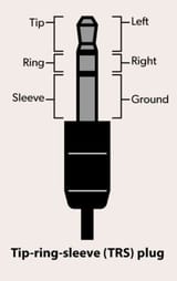
It'll be easier if you don't mind getting rid of the microphone function. Use a multimeter in continuity mode to find L, R, and ground. Plug a 3.5mm patch cable into the jack, place one probe on a contact on the bottom of the jack's PCB, and the other probe on the end of the cable- either tip, ring, or sleeve, and listen for a beep. The tip will be the left channel, the ring is the right channel, and the sleeve is ground. Then solder your left speaker to the tip contact, the right speaker to the ring contact, and both grounds to ground.
If you want to keep the microphone jack, then buy another TRS jack and do the same as above. You'll need to use two separate cables to connect them though.
Page 1