/ohm/ - Electronics General
Thread underwent thermal runaway (that's been used before though) or whatever:
>>2913061
>I'm new to electronics. Where to get started?
It is an art/science of applying principles to requirements.
Find problem, learn principles, design and verify solution, build, test, post results, repeat.
Read the datasheet.
>OP source:
https://github.com/74HC14/ohmOP
bake at page 10, post in old thread
>Comprehensive list of electronics resources:
https://github.com/kitspace/awesome-electronics
>Project ideas:
https://hackaday.io
https://instructables.com/tag/type-id/category-technology/
https://adafruit.com
https://makezine.com/category/electronics/
>Books:
https://libgen.is/
>Principles (by increasing skill level):
Mims III, Getting Started in Electronics
Geier, How to Diagnose & Fix Everything Electronic
Kybett & Boysen, All New Electronics Self-Teaching Guide
Scherz & Monk, Practical Electronics for Inventors
Horowitz and Hill, The Art of Electronics
>Recommended software tools:
KiCAD 6+
Circuitmaker
Logisim Evolution
>Recommended Components/equipment:
Octopart
LCSC
eBay/AliExpress sellers, for component assortments/sample kits (caveat emptor)
Local independent electronics distributors
ladyada.net/library/procure/hobbyist.html
>Most relevant YouTube channels:
EEVblog
W2AEW
Moritz Klein
>microcontroller specific problems?
>>>/diy/mcg
>I have junk, what do?
Shitcan it
>consumer product support or PC building?
>>>/g/
>household/premises wiring?
More rules-driven than engineering, try /qtddtot/ or sparky general first
>antigravity and/or overunity?
Go away
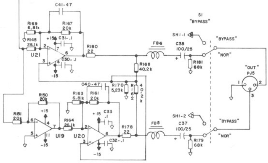
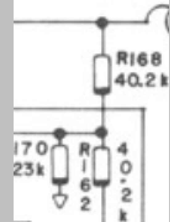
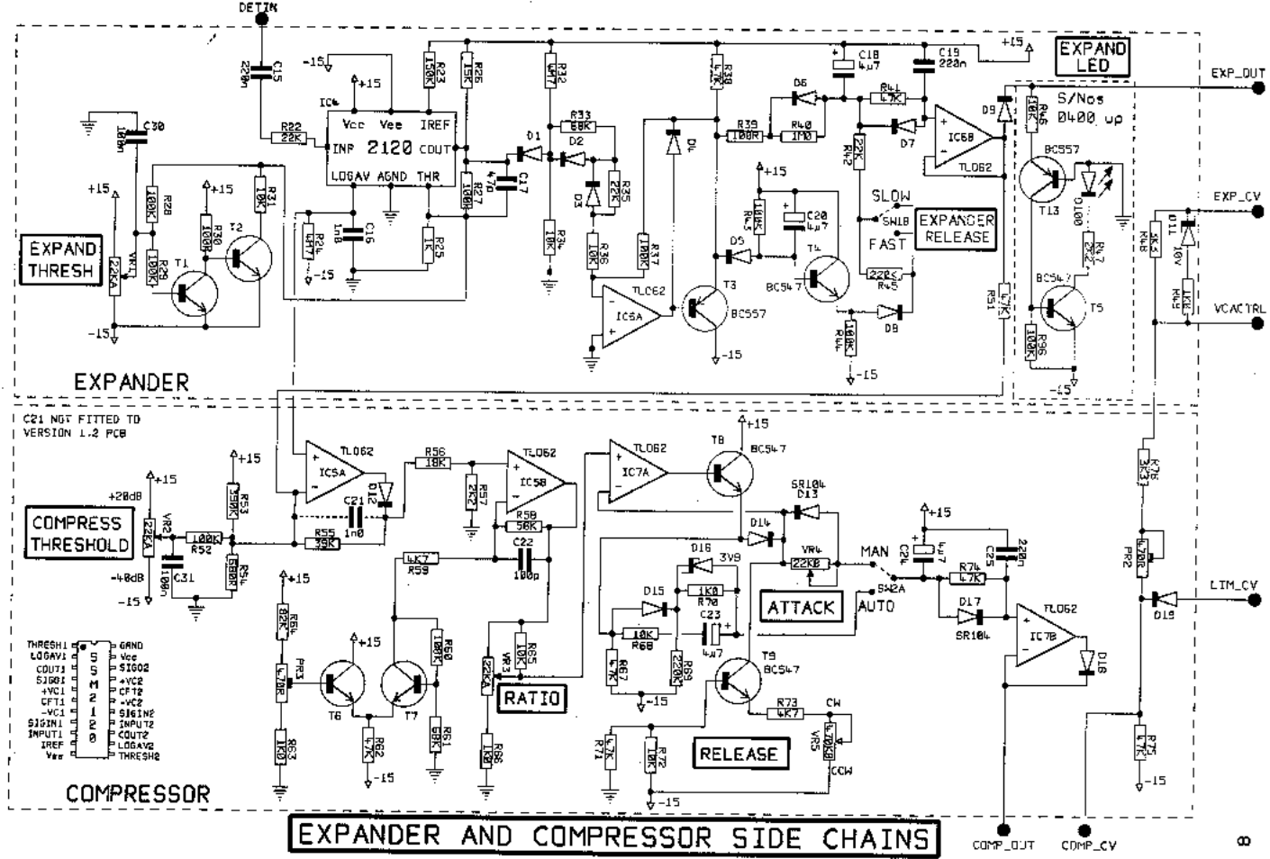
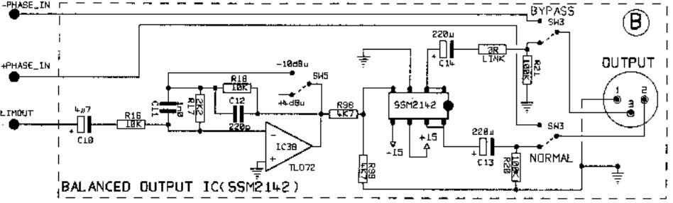
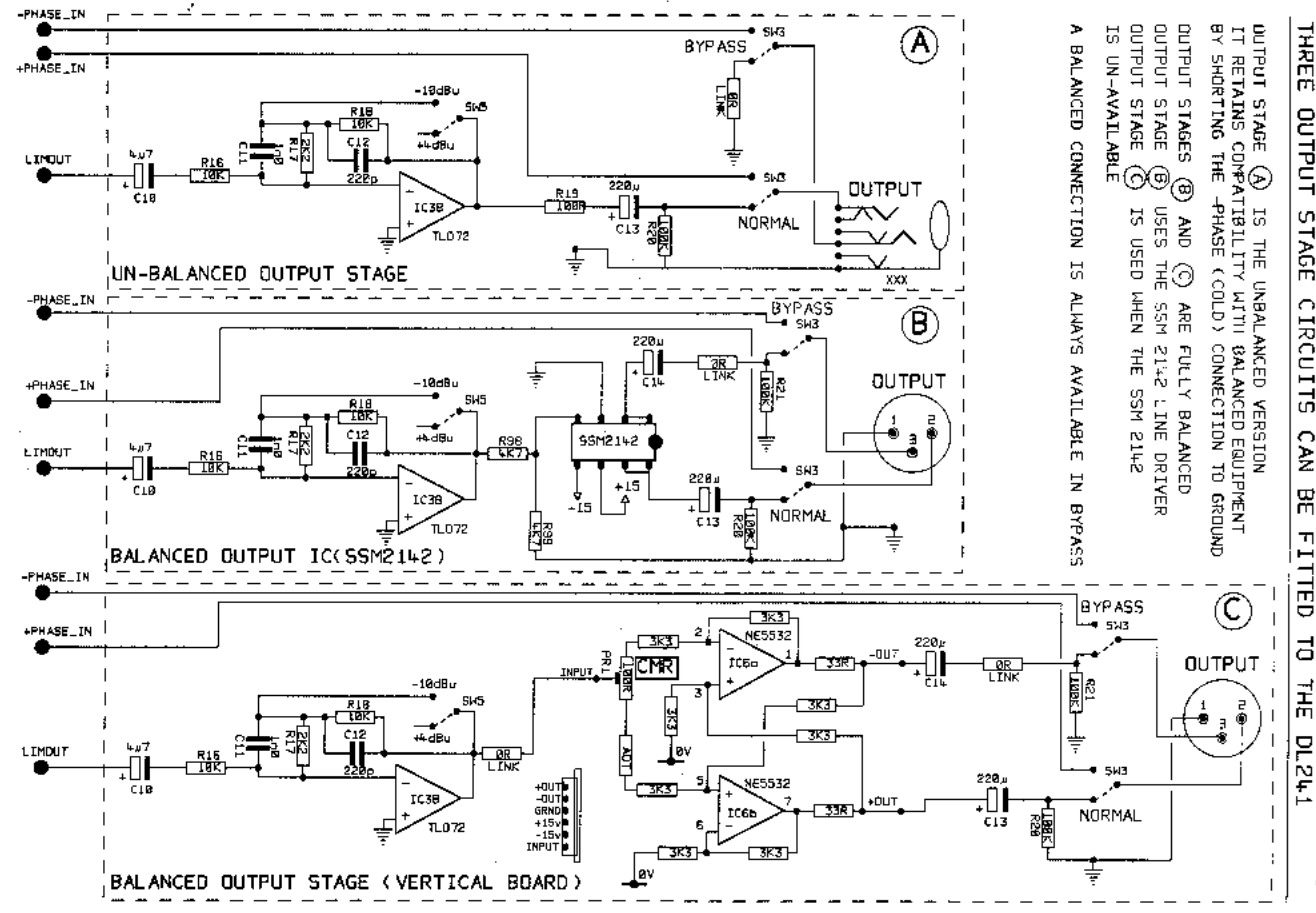
how to calculate the gain of this? i started drawing the circuit on circuitlab.com and they paywalled me!! i would prefer to improve my generalized knowledge and intuition of how it works rather than to just calculate it.
U20 and U21 are cross-coupled (servo-balanced) and the point is that you can connect it unbalanced with one output pin shorted to ground and the gain on the remaining output pin will be doubled to compensate. i don't get the mechanism of how it gets doubled.
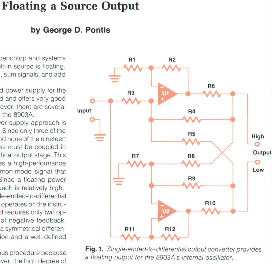
is there any particular reason for why (like DC offset of the U20 and U21 NE5534 op-amps) you would not want the circuit to be like on page 12 here so that the inverting U19 TL074 can be skipped:
https://hparchive.com/Journals/HPJ-1980-08.pdf
Anonymous
5/29/2025, 4:25:25 PM
No.2920502
[Report]
Anonymous
5/29/2025, 4:28:10 PM
No.2920505
[Report]
>>2920514
Anonymous
5/29/2025, 5:04:14 PM
No.2920513
[Report]
>> 2920493
> Buckling spring will probably always be popular
I used original ibm buckling spring keyboards a lot early in my career. I no longer wish to use them, I much prefer the flat square-keyed apple-like keyboards.
Do you know why those keyboard keys looked like that on old keyboards? Secretaries had long fingernails. As far as I’m concerned, all these zoomers coming into the office with their noisy rgb mechanical keyboards is a weird retro cult thing.
No doubt they were durable and reliable, however I remember dropping the buckling spring keyboard off the desk on my AT workstation, and about 80% of the keys flew off… springs and paddles went eveywhere. I damn near has a melt down, and putting back together probably burst several veins and shaved years off my life.
Anonymous
5/29/2025, 5:14:36 PM
No.2920514
[Report]
>>2920622
>>2920498
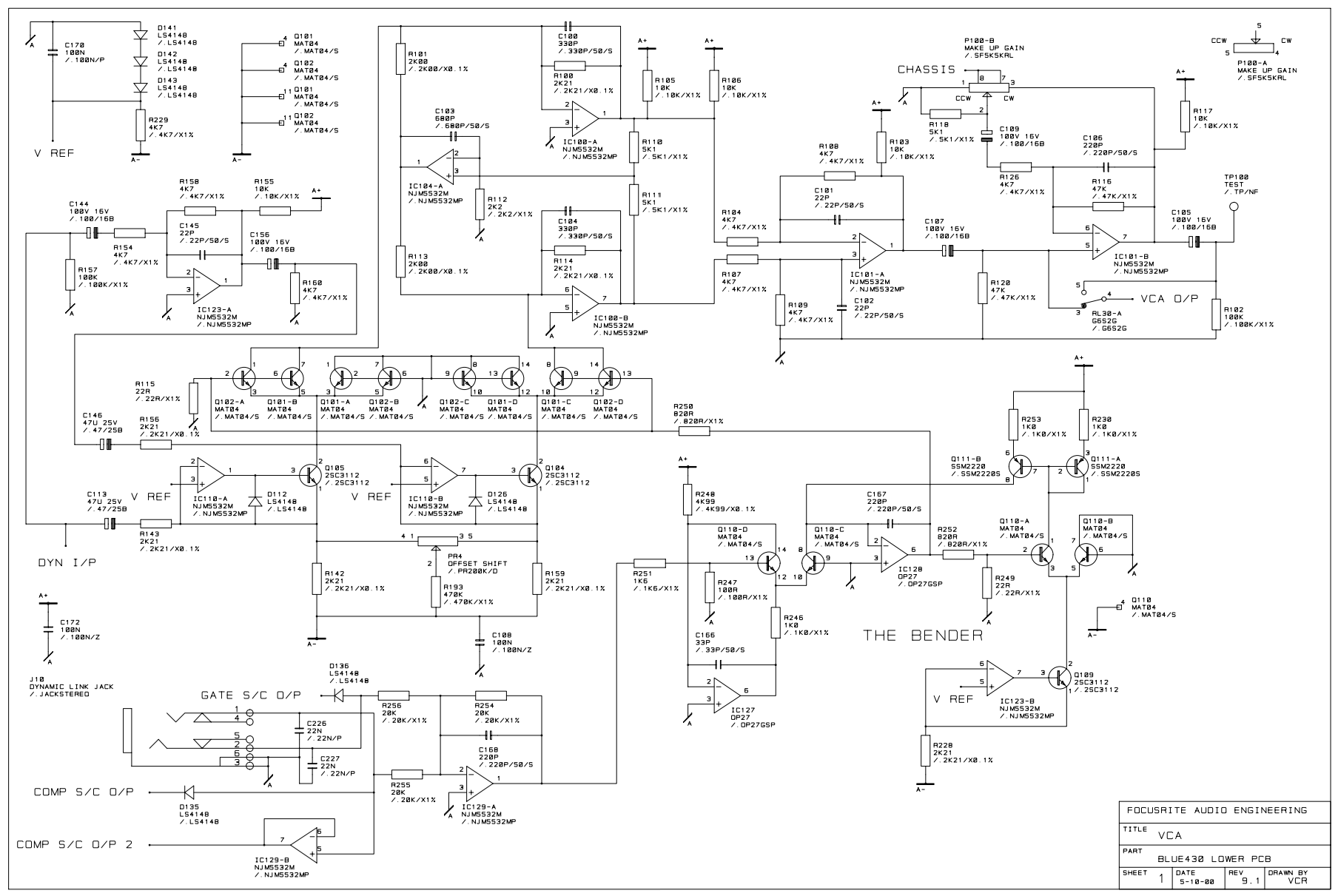
> blurry schematic, hurts eyes like those penthouse magazine pictures that had that blur filter
> inconsistent euro-style (wrong) pictorial depiction of diodes in place of resistors.
>>2920505
This is a nice schematic! One of the best, great attention to detail. I like the way the resistors are slightly thicker than the connections.
Anonymous
5/29/2025, 10:09:33 PM
No.2920589
[Report]
A bit of a niche request: Does anyone know a good resource that outlines all the info an entry level electrician would actually need? V=IR is nice and all, but like actual applicable info like identifying or diagnosing things out in the wild?
I have an interview panel next week and I'm pretty confident in my ability to bullshit through the mechanical aspects, but I don't even know how I know what I do about electricity. I'm getting interviewed by former tradesmen so I know that's their knowledge base
Anonymous
5/30/2025, 12:58:21 AM
No.2920622
[Report]
>>2920701
>>2920498
If you’re curious, I’d put that circuit and the more common 2-op-amp circuit in a spice sim and test the effect of DC offset from the input, as well as input offset voltage and current. If you want to do it analytically instead, you can ignore all the capacitors and chokes, and I suspect it wouldn’t be too difficult, even with the offset values in there. Ask wolfram for help reducing the equations.
To me it looks likely they’re using two inverting stages such that the gain can be lower than unity, but I’m unsure how the feedback loop calculates.
>>2920514
>diodes
Huh?
Anonymous
5/30/2025, 8:56:43 AM
No.2920701
[Report]
>>2920703
>>2920622
>>diodes
>Huh?
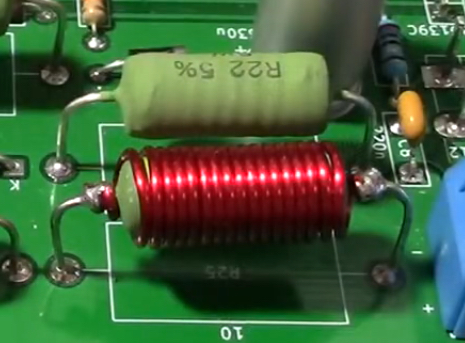
weirdly, some resistors have armbands on them
like they pointing out the jew ones
Anonymous
5/30/2025, 9:15:58 AM
No.2920703
[Report]
>>2920710
>>2920701
Just looking around the board, I suspect those are the tighter tolerance resistors. More compact than writing 1% by each one, but still strange. Never seen that on any other non-american schematic, but I suppose I haven't been looking for it.
Anonymous
5/30/2025, 10:11:42 AM
No.2920710
[Report]
Anonymous
5/30/2025, 11:29:06 PM
No.2920844
[Report]
>>2920853
>>2920877
>>2920495 (OP)
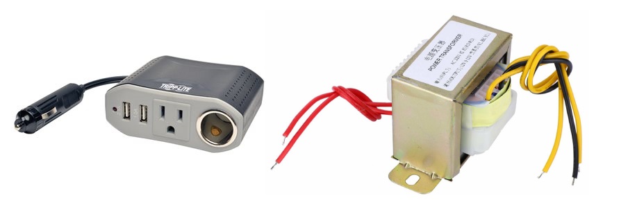
anons how do you measure big transformer that you have no idea where they come from?
like what is the clever way of doing so?
i have some from ups, that i dont actually know if they were 12, 24 or 48v and some other random that my father gathered with the years to use as solid wire rolls, but i plan to actually use them
Anonymous
5/31/2025, 12:55:58 AM
No.2920853
[Report]
>>2921004
>>2920844
>how do you measure
super easy
- make table showing which wires are connected to which
- note DC resistances on table
- assume coil with largest DC resistance is 120Vac - usually true
- using another transformer, apply low voltage AC across various windings
- measure voltages on all other windings to determine voltage up/down ratios
>>2920844
For knowing the VA rating, I suggest you just estimate based on size comparisons to known transformers with similar core materials. Unless you have an oscilloscope and a beefy enough power source to check the saturation curve. A lead-acid battery would probably work, you’d switch it with a beefy MOSFET from your function generator and slowly turn down the frequency to see when the steady current-ramp starts going bad.
Anonymous
5/31/2025, 3:50:19 AM
No.2920887
[Report]
>>2920907
>>2920877
> beefy MOSFET from your function generator
I thought mosfet was for switching not following a sine wave curve
Anonymous
5/31/2025, 6:05:35 AM
No.2920907
[Report]
>>2920887
Don’t give it a sine wave, give it a DC voltage out of the battery. A flat voltage will mean a steady current ramp. But you can’t leave the DC there for too long or it will draw too much current. Hence the MOSFET and function generator, to turn it on for a small amount of time repeatedly so you can get a repeating signal via scope. Slowly tweaking the on-time until you start to see the non linearity in the current curve should be safe.
Otherwise, putting a variable AC load or variable AC supply would work, if you can get a powerful enough one, but that sounds harder than the pulsed DC method, and harder to read.
whats the easiest way to get a standard 12v DC power supply and turn it into 12v AC?
Anonymous
5/31/2025, 7:14:45 AM
No.2920920
[Report]
>>2920954
>>2920909
50/60Hz? A bipolar-output audio amp with a signal generator.
Anonymous
5/31/2025, 8:14:16 AM
No.2920932
[Report]
>>2920962
>>2920909
>easiest way
this would be easiest if you already own these items, which every self-respecting red-blooded straight man in the world should
Anonymous
5/31/2025, 9:03:13 AM
No.2920954
[Report]
>>2920962
>>2920920
> Bipolar audio amp
This is what I’m thinking.
But you’d need roughly a 2000 W amp. That’s going to be expensive.
Plus, most bipolar amps only go up to 60-ish V on the output, you’d need 120 or 240, ideally.
Also I believe something like the most popular bipolar amp is a class AB, and that’s not going to have the greatest efficiency.
But, this would make a wonderful AC power supply for messing around, 20 Hz to 20 kHz, pure sine (or triangle, or whatever you want from your walkman or sig gen) … Three monoblocks would make a great 3-phase AC supply.
Anonymous
5/31/2025, 10:28:49 AM
No.2920962
[Report]
>>2921069
>>2920932
Yeah that’s the quickest way, but not necessarily the most cost-effective or (space)-efficient. I was assuming “easy” wasn’t just “quickest off-the-shelf” but more “pretty quick and good bang for the buck”.
Also you posted an image of a modified sine inverter, they don’t play nice with AC transformers. You need a pure since unit, which are more expensive.
>>2920954
>2000W
Do you actually need that much power?
> you’d need 120 or 240, ideally
The original post calls for 12VAC, not 120VAC. Conventional car audio amplifiers are designed to drive 4Ω loads with a 12V supply, I’m not sure if they’re bipolar but you can always drive two independent channels with opposite phases. Subwoofer amps drive even lower impedances, and can put out thousands of watts if you believe the label. Thick wires though. Automotive amps are also usually class-D too, so pretty efficient.
I tried to design a low-frequency ZVS power oscillator for driving EL wire once (1kHz) but it was unreasonably difficult to get it to oscillate. Big caps required. I bet 50Hz would be even harder.
i thought this guy was mistaken because i tried to decipher the text in the datasheet and i think he might be measuring incorrectly and the behavior of the ESD protection diodes is more complicated than what he expects
>The item is fake or not genuine. The genuine opa1612 ic has to test positive for diode at pins 2 and 3. These diodes are incorporated in the ic circuit as a way to protect against voltage overloads. The opa1612 ics that were shipped do not have these diodes incorporated, so they are not genuine at all.
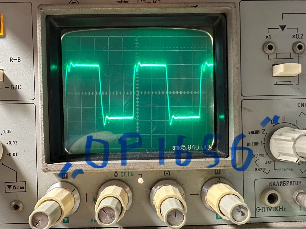
then i saw this guy with a 200hkz square wave on an oscilloscope who also mentioned diodes
>Fake. This is not opa1656, but NE5532, according to the frequency characteristics of the Chinese 5532, even the diodes between the 2 i3 legs are ringing like in the 5532, I do not recommend buying here, 100 percent will be found, think for yourself whether you need microcircuits 10 times more expensive, but in fact the same 5532
so what is this diode thing that apparently can be measured relatively easily to see if the op-amps are crap or not?
btw some of the other sellers are clearly different sellers (not samefags with a different account) and they get good reviews
https://www.diyaudio.com/community/threads/opa1612-from-aliexpress-no-counterfeit-but-why-so-cheap.399994/
Anonymous
5/31/2025, 4:01:40 PM
No.2921004
[Report]
>>2920853
thanks for the detailed instructions
>- using another transformer, apply low voltage AC across various windings
fuck, i am retarded, how i didnt think of this? i was looking into buying a cheapo signal general generator for that...
>>2920877
i have a usb scope, and an analog one that needs repairing, but i am pretty noob with it desu, but at least now i know what to look for.
thanks both of you, i was pretty clueless where to start looking
Anonymous
5/31/2025, 5:22:34 PM
No.2921021
[Report]
btw
>https://www.diyaudio.com/community/threads/opa1612-from-aliexpress-no-counterfeit-but-why-so-cheap.399994/
>Although specifications of OPA1612 (bipolar) indicate they are superior to that of OPA1642 (JFET inputs) in practice OPA1642 performs slightly better. Strange but found too many times to ignore it.
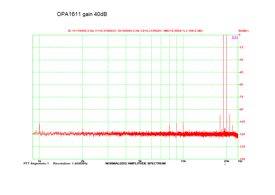
as far as this test is concerned, OPA1611 performs better than OPA1641
https://www.audiosciencereview.com/forum/index.php?threads/measurements-of-19-20khz-imd-of-various-opamps-at-gain-40db.10730/
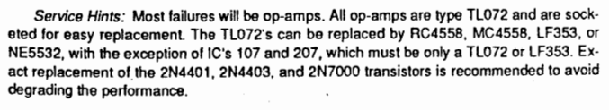
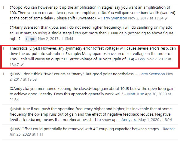
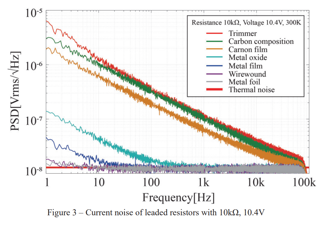
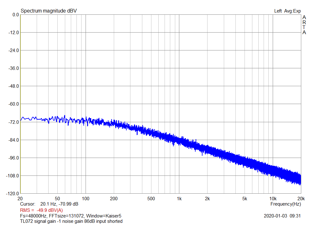
but replacing TL072 with OPA1612 might not be appropriate because of DC offset, input bias current, or current noise vs voltage noise, like in pic related they really don't want NE5532 for all of the ICs
Anonymous
5/31/2025, 5:25:36 PM
No.2921022
[Report]
another thing is that OPA1612 only has 20kOhm differential input impedance whereas OPA1642 has astronomically higher differential input impedance at 10^13 Ohm
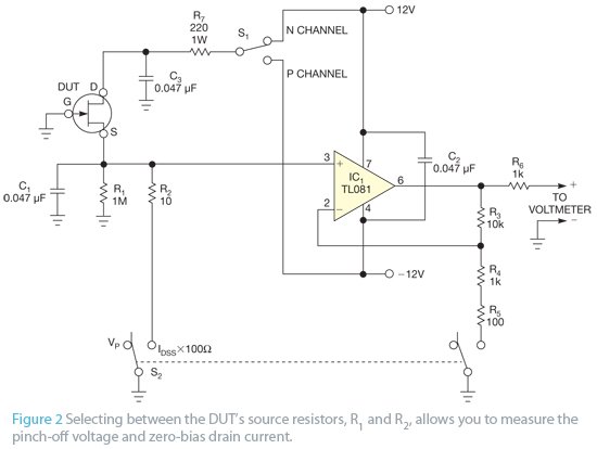
I want to build this circuit in order to characterize some mystery JFETs that are on some board that I'm trying to repair. Would it be possible to use a LF353 in place of the TL081? From what I see the TL081 has a larger slew rate and offset pins that don't seem to be used in the pictured circuit while the LF353 has a high input impedance.
Anonymous
5/31/2025, 5:39:03 PM
No.2921026
[Report]
Anonymous
5/31/2025, 9:31:25 PM
No.2921069
[Report]
>>2921100
>>2920962
>2000W need that much power?
Nice to have. If you want to test transformers properly, you do. You need to monitor the heat output under heavy load over hours. I also test the ability of a transformer to sustain a short circuit indefinitely, but purpose-built safety transformers work a bit like ballasts and are not efficient.
Also, ballast testing :)
> 12VAC
Yeah, the obvious (and cheap-ass, imho) way this is done on UPS systems is a 1:10 step-up transformer with the primaries using wound bus bar @ 100 A. Cars drive 4Ω to get the power up on 12 V i guess.
> class D
I don’t understand how they work, they seem like magic if you ask me, i don’t see how the hell you can filter out the whole pwm signal with a couple of tiny caps, and you’d need a very specific speaker coil/inductor…
> zvs
Seems like more magic, like a tesla coil for current instead of voltage, or a big-ass joule thief.
> zvf, got the frequency wrong, accidentally cooked my liver with radio waves while it was still in my body
Anonymous
5/31/2025, 9:43:17 PM
No.2921075
[Report]
>>2921002
The thing people don’t understand is the difference between packaging and wafer/die production.
TI (let’s say, for example) makes the wafers, and from there, they get sold, distributed, shipped, and contracted to various packagers around the world. Sometimes the wafers are lost, test out of spec, stolen, recovered, re-sold, etc. finally, they get to china (years later), get cut, put on weird lead frames, epoxy encapsulated with whatever markings.
All this can happen, while the die is 100% original authentic vintage texass instruments fabbed in the USA by white people.
Anonymous
5/31/2025, 9:59:05 PM
No.2921084
[Report]
>>2921025
They’re both 25 – 50 cent parts.
I just build them and test it, rather than getting into analysis paralysis and running them on shitty simulators and whatnot. We even just ran into
>>2920498 where it defied simulation.
That said, higher slew rate is generally more gooder in that it can drive more current.
So, if you have a high impedance voltmeter, probably fine. Also you can buffer it with some other random op amp to get a higher current.
Presumably, you are doing comparative characterization, wher you get a feel for a couple of known-good DUTs, the test the other ones relative to the known goods without worrying about the absolute values.
Anonymous
5/31/2025, 10:04:15 PM
No.2921089
[Report]
>>2920495 (OP)
i want to measure a 0-200V DC low impedance source with an ADS1115. i'm running the ADC it at 3.3V so this means 2.048V full scale. i want to measure this voltage differentially. i know that i need to worry about input impedance of the ADC but i'd prefer to have high value resistors due to the source being 200V DC low impedance.
what is the "right" way to do this? obviously i need to divide the voltage down and buffer it for the ADC but i'm getting hung up on wanting to do this differetnially and then converting it to single end for the ADC (or using the ADC's differential input functionality).... and then dealing with op amp offset.
Anonymous
5/31/2025, 10:12:58 PM
No.2921094
[Report]
>>2921025
TL081 seems to have higher slew rate and bandwidth
Anonymous
5/31/2025, 10:29:54 PM
No.2921100
[Report]
>>2921657
>>2921069
Do you know how a buck converter works? Can you see that replacing the diode with a transistor for synchronous rectification also works? There, you’ve got a class-D amplifier. High frequency PWM buffered by a hard-switching push-pull transistor pair, and then filtered by an LC filter. With the right sized filter, any switching noise is well below the audible level. Class-D amps often run open-loop, as in their input voltage is directly proportional to duty-cycle, but there are cases where feedback is used.
Your reference to small capacitors suggests to me that you’re thinking of those filterless class-D chips/modules you get on Ali. They work because magnetic speakers are current-mode devices, it doesn’t really matter if the voltage waveform moves in stops-and-starts so long as the force exerted by the electromagnetic changes smoothly enough. And the momentum of the speaker cone will smooth out the really high frequency noise.
Anonymous
6/1/2025, 1:51:10 AM
No.2921149
[Report]
>>2921163
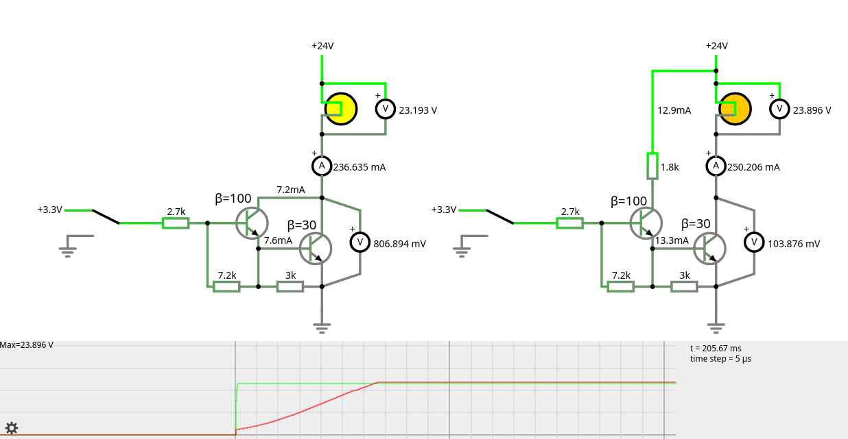
Tying driver transistor's collector to +24 V reduces the saturation voltage across the power transistor wrt. Darlington configuration, but turns the 5 W lamp on slowly (70 ms). Maybe these characteristics could be useful in certain applications.
Man I wish there was a neural network that went through a chip’s datasheet and extracted the pinout and package information to create CAD models. With the nice kind of symbol, where the inputs are on the left, and the outputs are on the right, and the power is on the top and bottom. Not the shitty IC pin order. And even make and verify spice models for simpler parts like transistors.
>>2921002
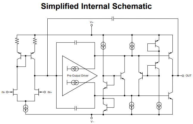
It’s not the ESD diodes, but rather two antiparallel diodes between the inverting and non-inverting inputs. In negative feedback operation, the two inputs of an op-amp must be approximately equal to each other, so the presence of diodes would do nothing here. But operating without negative feedback, or even as a comparator, could easily result in greater than 0.6V difference between inputs. Manufacturers often put diodes between the inputs to prevent their parts being used outside their intended operating regions, which may cause damage to the transistors within. In this case, the OPA1612 should have these diodes (read the datasheet, they’re in the functional block diagram on page 1), so the absence of these diodes suggests a different chip.
I got fake TL072s from AliExpress from a reputable seller, if you think you can get anything more exotic than that you’re just asking to get scammed. Particularly if the price per chip is lower than from the official vendor sites like Digi-Key or LCSC.
>>2921149
Why not a sziklai?
Anonymous
6/1/2025, 6:51:01 AM
No.2921199
[Report]
>>2921213
>>2921163
> Man I wish there was a neural network that…
Man, I wish AI were real, too.
And, if it was real, that it would be put to good use.
>>2921199
AI is the mother of all psyops designed to make you believe that humanity is obsolete and resistance is futile. It's a mind-killer weapon.
"Idols will speak and move about."
Anonymous
6/1/2025, 9:17:59 AM
No.2921216
[Report]
>>2921218
>>2921213
We were cursed to work the land and earn our food. Any idea of post scarcity is ridiculous
Anonymous
6/1/2025, 9:21:20 AM
No.2921218
[Report]
>>2921213
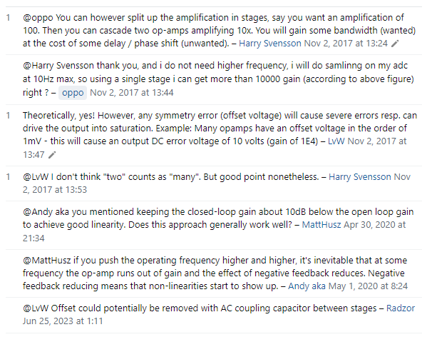
Sorta, but you’re dumping all AI systems into one basket. Language models are what we have the most exposure to, and despite how incompetent they seem real human beings are relying on them more and more. But PINNs and other pattern recognition tools are probably even more impactful. Like alphafold, the one that turned protein folding from some esoteric artform into something we could start relying on. Or reverse kinematics for legged robots on uneven terrain. Extremely narrow neural tools that replace inefficient algorithms are an incredible technology that I can’t wait to see more of. And if summarising documents and rewording text is something that language models continue to improve on, I look forward to lawyers being obsoleted. Nothing of value would be lost.
>>2921216
Agreed. Even if we find ourselves in a landscape where machines have managed to replace intellectual jobs, we’d just become Amish.
Anonymous
6/1/2025, 11:12:31 AM
No.2921233
[Report]
>>2921243
>>2921163
>OPA1612 functional block diagram
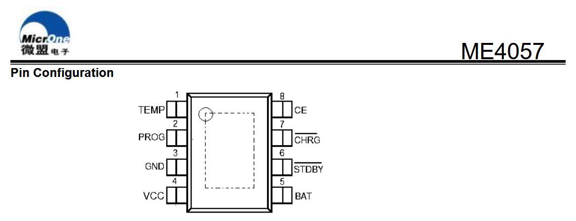
oh i see but what about OPA1642? i don't know how to read pic related lol. why does it look like IN- and IN+ are connected directly to each other
Anonymous
6/1/2025, 12:15:23 PM
No.2921243
[Report]
>>2921233
>what about OPA1642?
Because there are no diodes shown between IN- and IN+ I'd assume there's no such diodes here, but you can also check the specifications for a maximum allowable differential input voltage. It says +/-VS, so it can handle a differential voltage as large as the supply, so there aren't any such diodes. The OPA1612 has no such value listed in its Absolute Maximum Ratings page, but in section 7.3.4 it mentions the diodes for limiting differential input voltage specifically.
>why does it look like IN- and IN+ are connected directly to each other
They're on either side of a JFET long-tailed-pair. Long-tailed-pairs are the backbone of any operational amplifier circuit, discrete or monolithic.
Note that the 1642 is a JFET-input op-amp, while the 1612 is a BJT-input op-amp, so you can expect a lot of characteristics related to their inputs to differ between them. Especially offset voltage and bias current. I would assume the two types of op-amps are intended for somewhat different uses (though likely with significant overlap). Read the application notes and detailed descriptions in their datasheets for more. From my limited understanding, JFET-input op-amps have exceptionally high input impedance, making them better suited for sensing very weak signals like microphone capsules, but there may be more important differences.
Anonymous
6/1/2025, 12:35:11 PM
No.2921247
[Report]
>>2921256
hmm so should i go whole hog with an oscilloscope to test the op-amps properly because it seems that acceptable quality ones can be had on the used market for like $100 or less
or set up a breadboard with a resistor for 1000x gain and measure the frequency response with a sound card instead of an oscilloscope to at least know the tier of component like if it's one of the OPA op amps and not something much older/cheaper
maybe with an oscilloscope i'd be able to distinguish subtle differences between OPA1612 and OPA1642
Anonymous
6/1/2025, 12:48:38 PM
No.2921251
[Report]
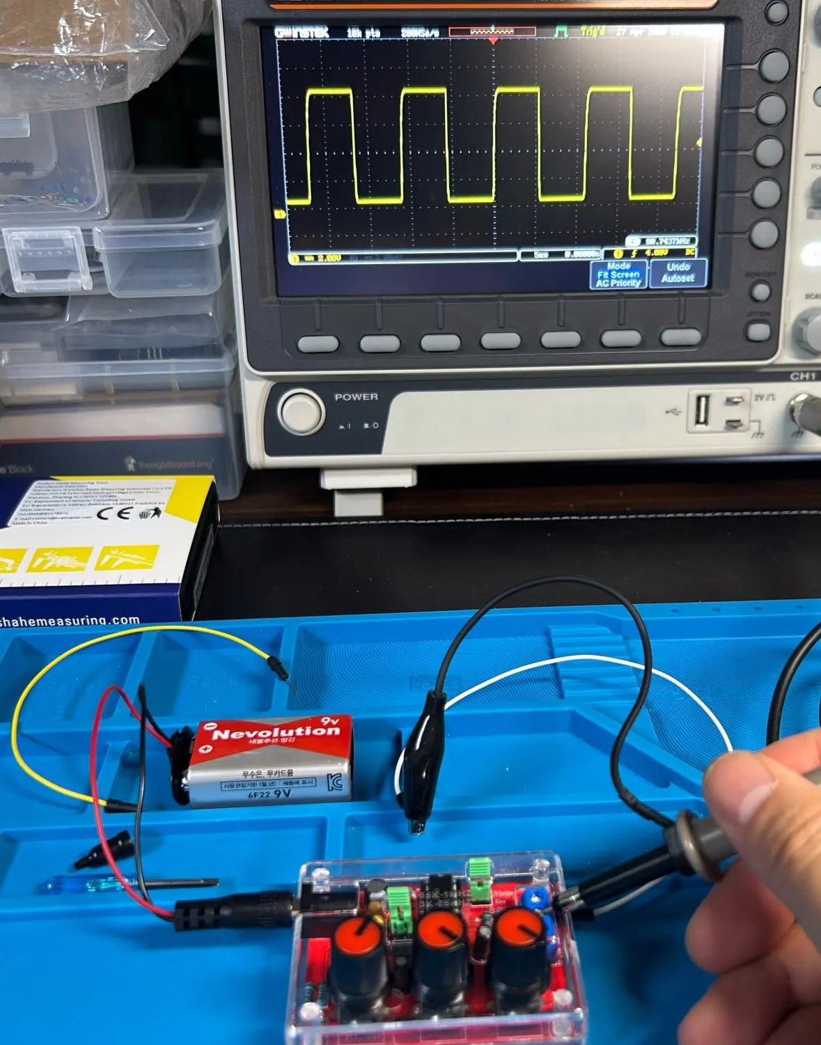
what kind of a signal generator do i need
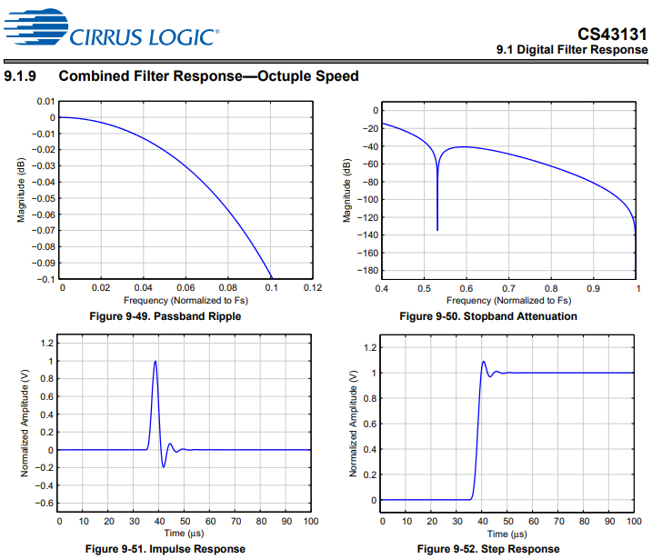
pic related looks weak for octuple speed (392khz) although i don't know how it works like if you feed it a square that's bandpassed in software will it still alias from the response above nyquist (0.5 Fs)
Anonymous
6/1/2025, 12:51:36 PM
No.2921254
[Report]
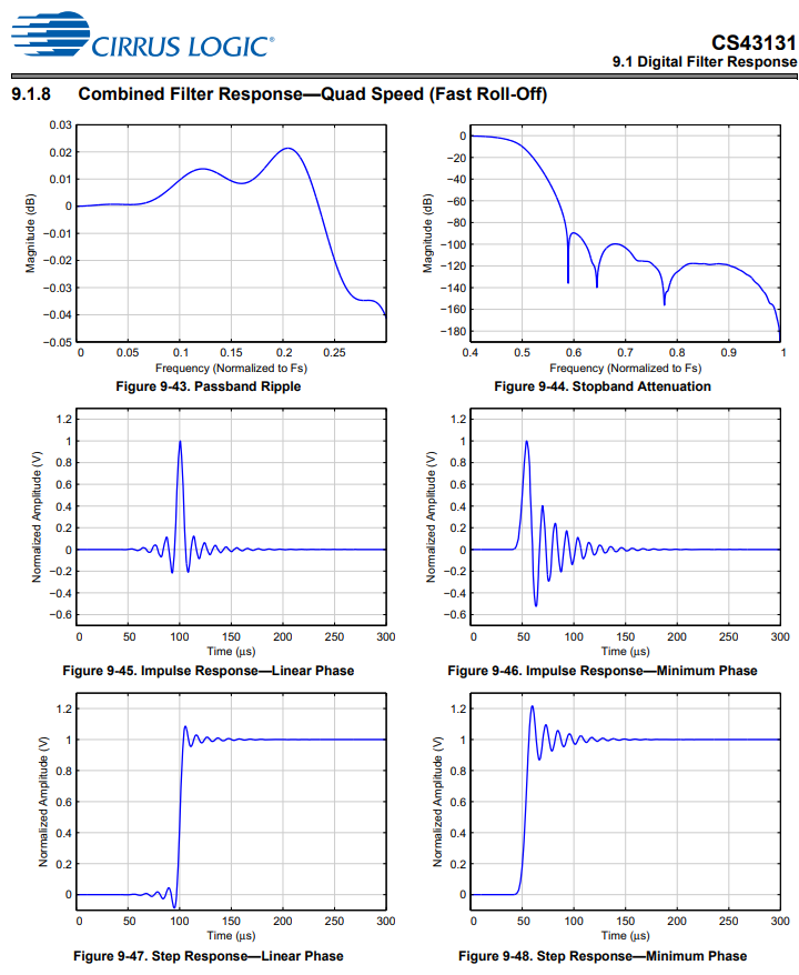
this is for 192khz
Anonymous
6/1/2025, 12:53:56 PM
No.2921256
[Report]
>>2921247
You could definitely measure the difference with a sound card, at least if you gave it a worst-case scenario low-stability high-gain circuit. But that’s not really a useful metric. If your sound-card has high sampling rate you might be able to tell the difference on a normal circuit, and there may be oversampling methods to employ that could net you a higher effective sampling rate from a known repeating signal source, but a scope would be more useful overall. Even some USB or little handheld scopes aren’t bad, but for audiophile uses I’d be looking for at least a 1-2 hundred kHz bandwidth. Storage would be nice, and being able to measure THD in the scope with an FFT would be really handy for audio too, which is beyond almost all CRT scopes.
Anonymous
6/1/2025, 1:00:13 PM
No.2921258
[Report]
>392khz
*384khz
Anonymous
6/1/2025, 1:22:47 PM
No.2921260
[Report]
this cheap PWM generator might be enough to reveal weak op-amps like this pic
>>2921002
it can be set to up to 1MHz
Anonymous
6/1/2025, 1:23:54 PM
No.2921262
[Report]
forgot pic
Anonymous
6/1/2025, 1:28:22 PM
No.2921264
[Report]
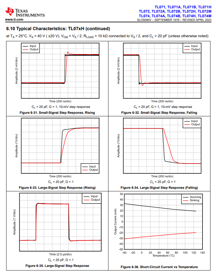
the large-signal step response looks almost square though damnit this shit is complicated
Anonymous
6/1/2025, 1:32:09 PM
No.2921266
[Report]
>>2921268
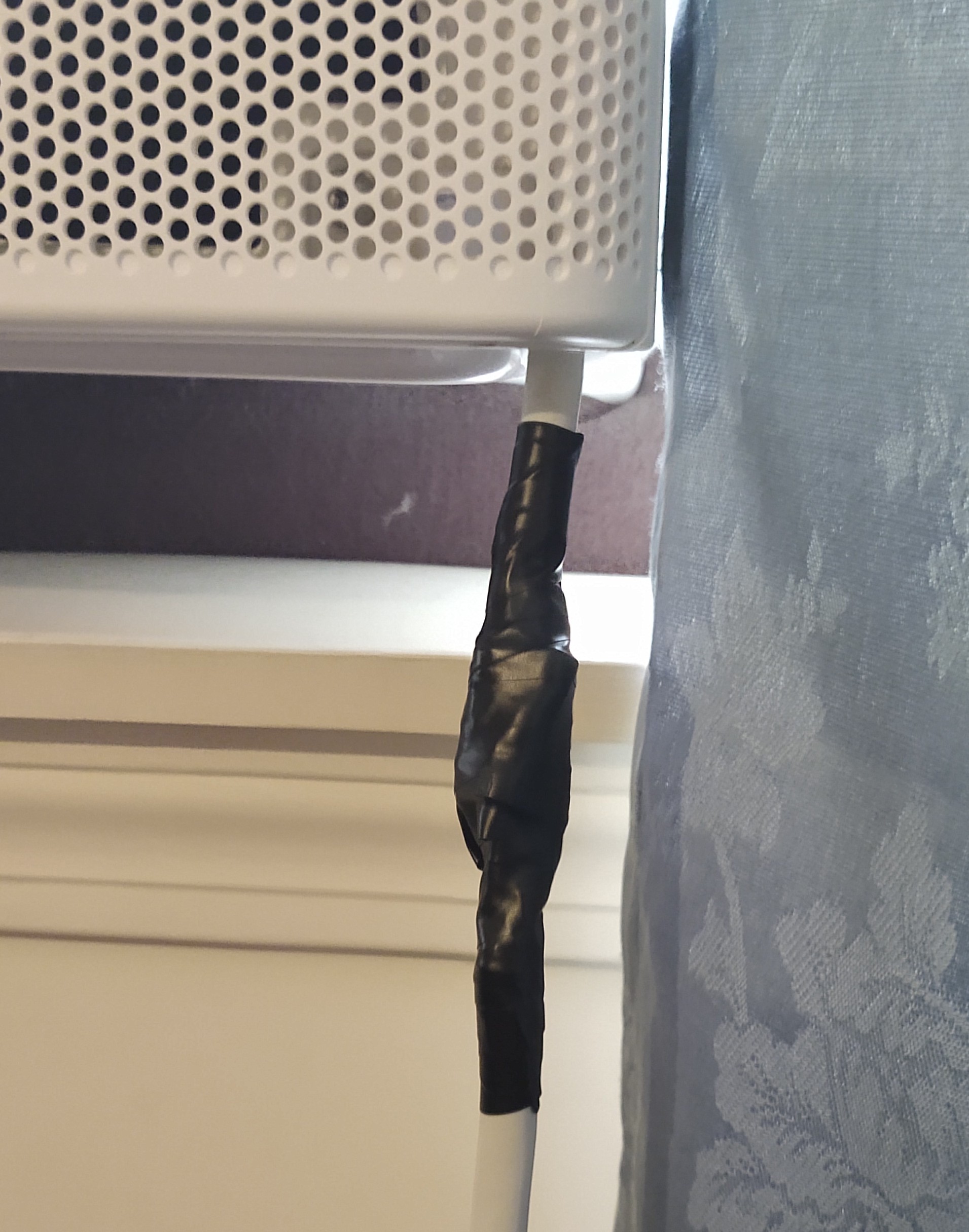
Maybe this is not quite on topic, but it is electrical: I have an irrigation pump with a short cord that plugs into an extension cord from the house. The connection leads of the pump’s cord get hot enough to burn me after running it for a couple of hours. Is there any recommended way to mitigate this, or at least keep it from being a fire hazard? The previous homeowner recommended using the shortest extension cord that will work, which makes some sense to me, but I bet there’s more that can be done.
Anonymous
6/1/2025, 1:53:43 PM
No.2921268
[Report]
>>2921266
Use thicker wires. If that means upgrading the wire built into the pump too, so be it. The connectors often get hot too, maybe try bending the contacts in the socket to put more force on the connection if this is an issue, or just rewire it with a long enough wire in the first place. Consider putting on a higher current connector and wiring it into an appropriate wall socket with the appropriate inner-wall wiring and breaker if you’re extra worried.
Anonymous
6/1/2025, 2:49:21 PM
No.2921275
[Report]
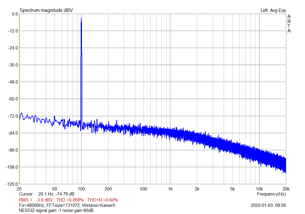
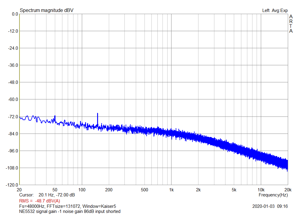
>You can also measure noise: short +IN to ground, (always with the "revealing" 100X attenuation/gain setup), feed output to another 100X gain block, noise will be amplified 10000 times and easily visible on any scope, even a Software one.
the noise floor is like -120dB even at +40dB (100x gain) 3.4V peak to peak output
https://www.audiosciencereview.com/forum/index.php?threads/measurements-of-19-20khz-imd-of-various-opamps-at-gain-40db.10730/
so how does that even add up if you 100x it again it would be 340V or is it because the input is shorted and there are no peaks it can still output the noise even with like a 9V better with voltage dividers for +4.5V and -4.5V
could you do +80dB (10000x gain) in one go like with 100 ohm input and 1M Ohm feedback or do you need at least 1k Ohm input resistor
Anonymous
6/1/2025, 2:50:21 PM
No.2921276
[Report]
>9V better with voltage dividers for +4.5V and -4.5V
9V battery
Anonymous
6/1/2025, 3:59:58 PM
No.2921286
[Report]
???
Anonymous
6/1/2025, 4:10:10 PM
No.2921288
[Report]
two batteries is still pretty easy to set up so it'll be a pretty minimal setup with two resistors with small capacitors, an IC socket and an unbalanced audio out that i can measure the noise level of with a sound card. i'll have OPA1612 OPA1642 etc to compare against vintage TL072 NE5532 etc
Anonymous
6/1/2025, 4:22:49 PM
No.2921289
[Report]
>apply DC to thing I just finished
>doesn't work
>"huh maybe I got the 'odes switched around
>swap wires
>POP
>sizzle sizzle sizzle
>mfw
Anonymous
6/1/2025, 4:34:25 PM
No.2921292
[Report]
Anonymous
6/1/2025, 7:18:11 PM
No.2921333
[Report]
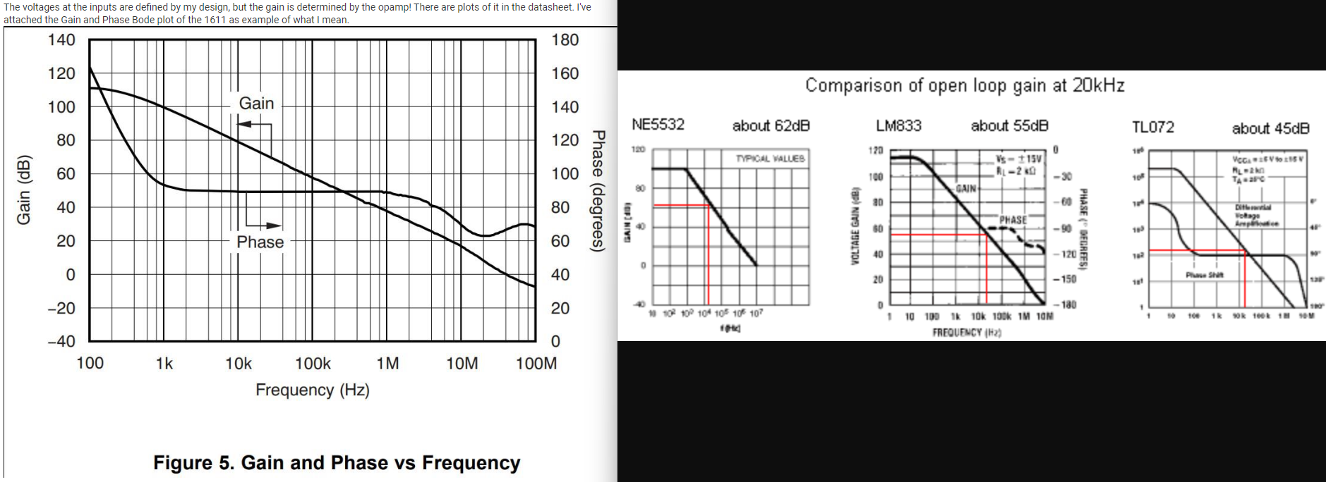
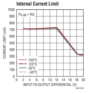
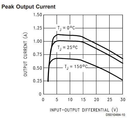
not sure what they mean, the datasheet says 114dB minimum and 130dB typical open-loop gain for a 10k Ohm load but the roll-off in pic related is steep so idk if i can have +80dB gain across the audible frequency spectrum from a single op-amp even if it's just the noise that i'm looking for.
Anonymous
6/1/2025, 7:26:17 PM
No.2921336
[Report]
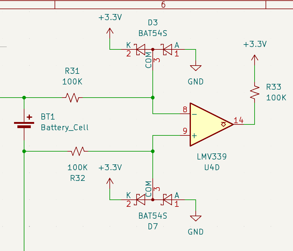
10V DC offset with +/-3V power supply is recoverable with an AC coupling capacitor?
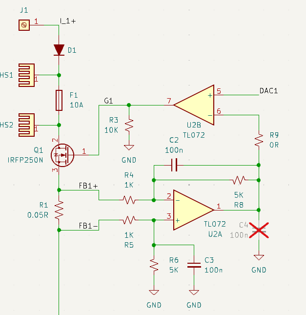
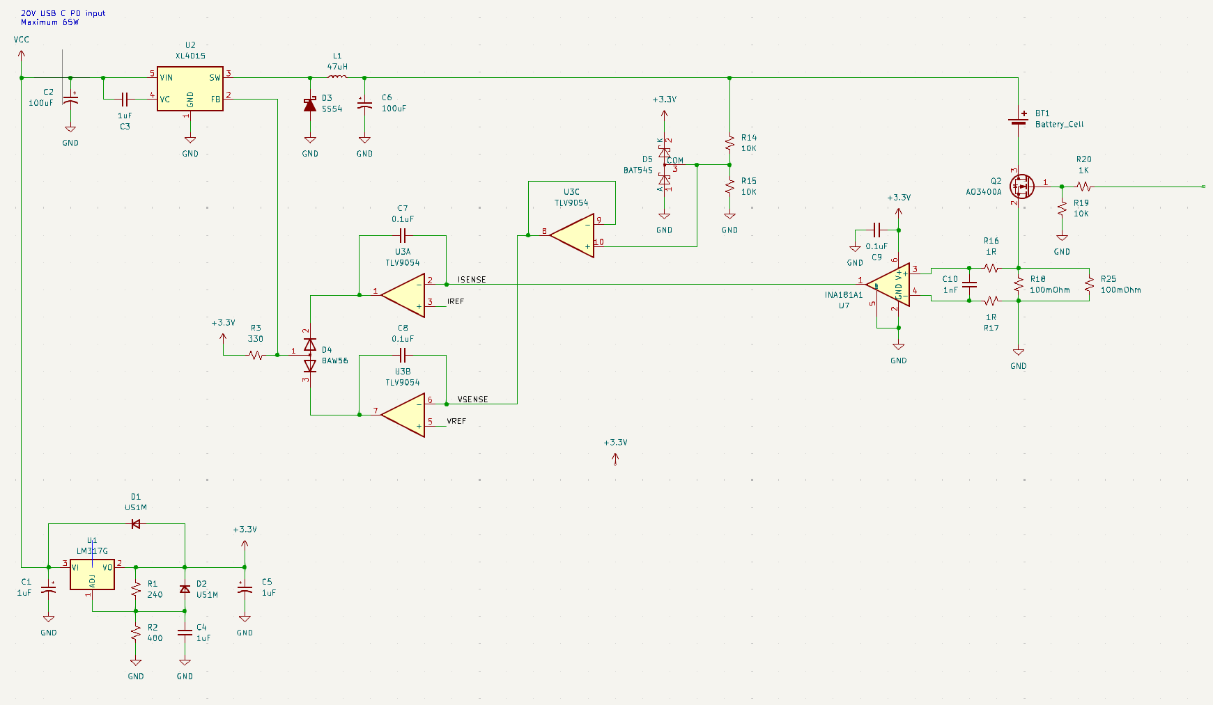
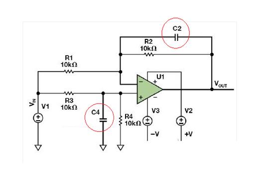
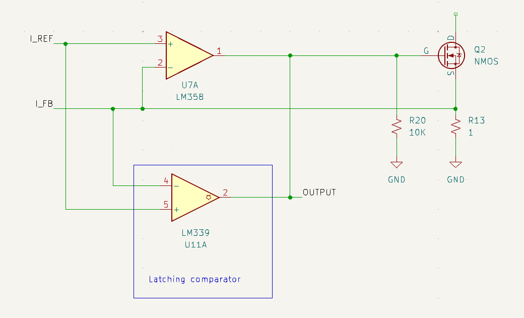
i'm making an electronic load. pic related is the basics of it. the DAC will output 0 to 2.5V. worst case scenario is i'll have -25 mV offset from U2A (5 mV max input offset * 5 gain) which means 1.25 mA of current flowing through R1 while my DAC is at 0V. obviously i can't deal with this in software because my DAC can't go any lower than 0V.
i therefore need to trim the offset and i found AN-31 which lists offset trim configurations.
https://www.ti.com/lit/an/snla140d/snla140d.pdf
do i do the offset at the differential amplifier (U2A)?
or should it be done at the open loop amplifier (U2B)? if so, how do i do this?
Anonymous
6/2/2025, 3:15:08 AM
No.2921425
[Report]
>>2921431
>>2921421
Either use low offset voltage op-amps (CMOS or chopper, not JFET), or add a trimpot somewhere. Probably between the op-amps, it looks like a pain to put one on the sense amp but it’s doable by adding a (buffered) voltage offset to the grounded side of R5/C3.
Anonymous
6/2/2025, 3:41:22 AM
No.2921430
[Report]
>>2921431
>>2921421
Why do the heatsinks need a 10 A fuse between them? HS is heatsink?
>>2921425
i chose jfet because i didn't want to worry about input bias current at low DUT current.
>>2921430
the heatsinks will be bolted to the reverse polarity diode and the mosfet with no silpad for maximum thermal conductivity. the fuse is to protect the DUT if the FET blows. i don't want a battery short circuiting and dumping 100A+ into a flaming FET.
Anonymous
6/2/2025, 7:09:25 AM
No.2921457
[Report]
>>2921431
CMOS op-amps also have negligible bias current. Furthermore, you could use a pair of high-gain non-inverting op-amps to amplify either end of the current sense resistor, both adding their own input offset voltage, then use a low-gain differential amplifier to cancel out the non-inv-amps’ offset while minimally contributing its own. I’d probably just do 5 and 1 for the gains, but 10 and 1/2 or even higher might be stable enough and give even better results. Assuming it won’t hit your rails. Making a discrete instrumentation amplifier may be able to leverage the same offset cancelling, I forget.
Anyhow, the TL072 is not a recommended op-amp for DC uses, shop around looking at datasheets. Do you need to sense down to the 0V rail, or are you running a bipolar supply? Because ground sensing will limit your options somewhat.
Anonymous
6/2/2025, 7:45:53 AM
No.2921464
[Report]
>>2921473
>>2920495 (OP)
Posting here, might need to be in the stupid questions (I feel stupid).
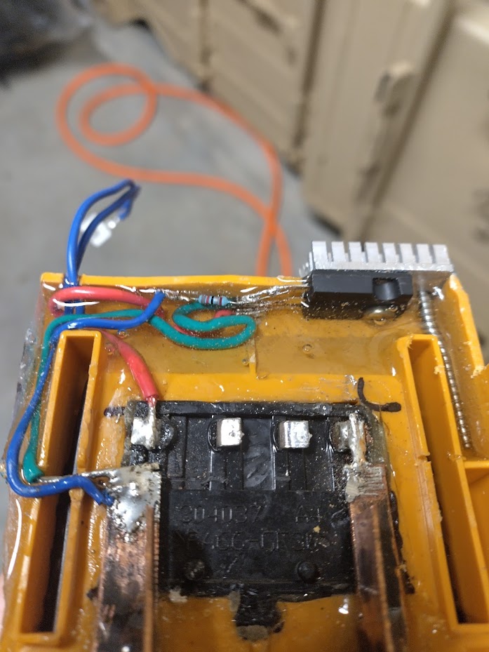
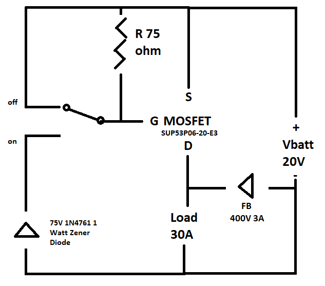
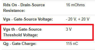
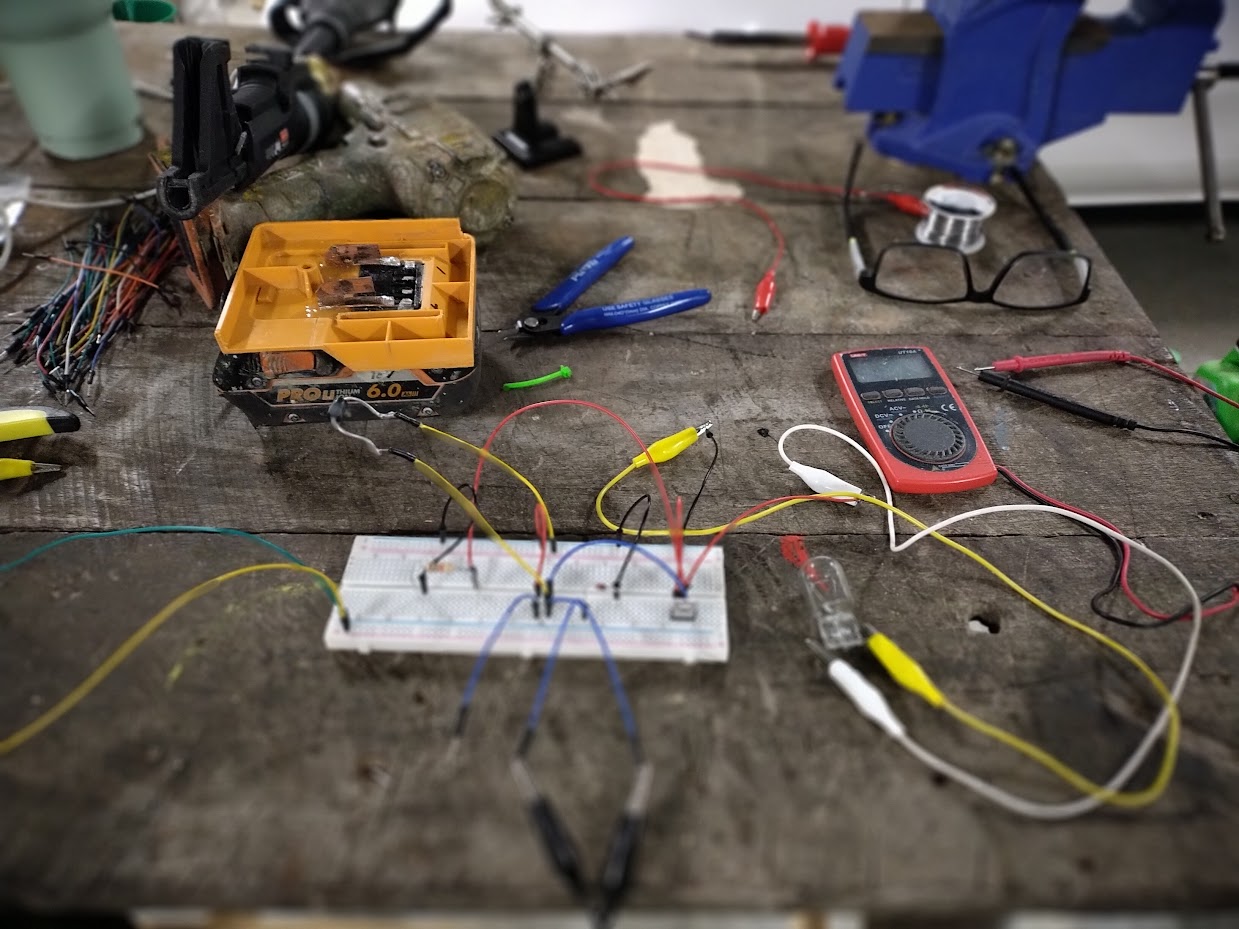
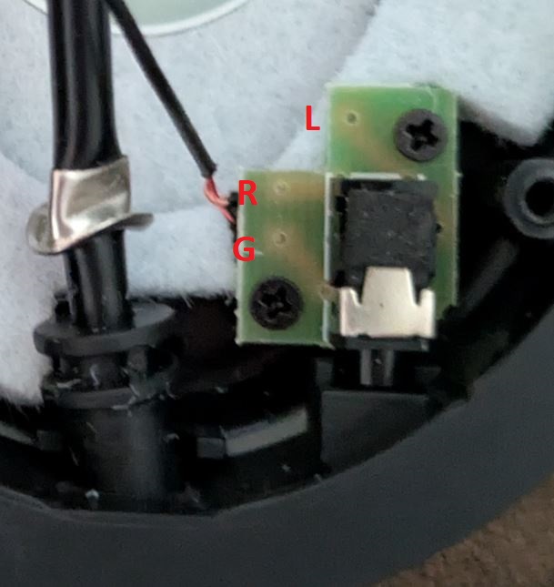
I'm trying to use a microswitch to switch a cordless tool under full load. I assumed I would be able to get an off the shelf transistor to do the job, but when I work out the values it would need It gets pretty hard to find anything.
The battery can output 30A, theoretically, and has a full voltage of 20V. Is there PNP transistors that can continually handle 30A? Should I be using a relay or contactor or something else?
I went to all the trouble of jury rigging a setup (picrel) and it worked, so I potted it and it then proceeded to permanently close circuit at first use. I had incorrectly identified the current at 50%.
>>2921464
You’ll want to use a MOSFET, they drop a lower voltage across their terminals and hence dissipate less heat in the <100A range. If you buy a sufficiently overrated FET (e.g. GL200N06), you’ll be able to avoid needing a heat-sink altogether. Because MOSFETs are voltage-triggered and are usually driven in the 9-15V range, you may need some additional considerations with regards to gate driving. Like a zener diode+resistor.
More importantly though, do you have a freewheel diode to prevent inductive kickback from the cordless tool from frying your transistor? A freewheel diode rated at sufficient peak current, at that. Unless you want to use a dedicated motor driver IC or half-bridge.
Anonymous
6/2/2025, 10:26:00 AM
No.2921494
[Report]
>>2921499
>>2921473
Thanks for the help, I'll read up on mosfet as a switch, adding a couple extra components would be no biggie.
Inductive kickback isn't something I even considered as it is a brushless tool. I thought as it is high frequency/voltage that there would be no feedback from the armature through the brainbox in the drill. I may toss the tool on a test stand and see if I can make current by spinning it. Also this thing is going to be attached to a fully bedded 3" chipboard screw in hardwood when the circuit is broken, there will be no spin-on.
>>2921494
If it’s a brushless tool, suddenly cutting power to it shouldn’t cause kickback as the motor driver should take care of that. Having said that, while I assume cordless tools are electrically robust enough to handle power being disconnected (e.g. their battery being removed), I’m unsure how they’d safely shut off in such a situation. It will probably just self-power from the back EMF until there’s no power left, it will likely never spin fast enough to overvolt the driver as that would mean spinning faster than with full trigger pull.
You may also be able to just send a small low-power signal into the electronics of the tool (especially the trigger mechanism) to tell it to turn on and off remotely, but if your device is replacing a battery and not modifying the tool then that isn’t an option.
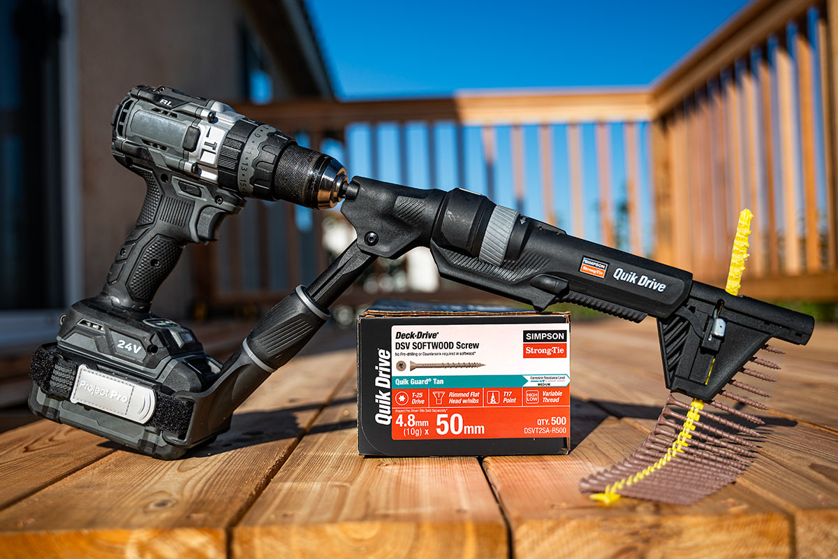
What’s the project anyhow? Some sort of screwing end-stop?
Anonymous
6/2/2025, 4:11:31 PM
No.2921534
[Report]
>>2921499
I considered modifying the tool, but usually the entire internals are potted so I would be tearing down the variable trigger and thereby permanently modding the tool.
Yes, that is exactly what this is. I need to be able to load any fastener of any drive design into a collated driver (in this case the simpson strong tie picrel). The tool relies on driver camout by simply maxing out it's travel. The camout is somewhat acceptable on a robertson bit, getting maybe 1000 drives before replacement (that's about 20 minuites). I need to be able to drive security torx, philips, and potentially tamper resistant, but moreover I don't want to be limited to the handful of options I can get for the tool where I live.
The jury rig I had worked dynamite (until it didn't). Full torque until the switch tripped and instant stop.
Anonymous
6/2/2025, 4:45:12 PM
No.2921540
[Report]
>>2921684
>>2921499
> overrated mosfet
> flyback diode
Both are cheap insurance, if you ask me. Especially if you’re gonna pot the thing under epoxy.
Anonymous
6/2/2025, 7:07:18 PM
No.2921569
[Report]
>>2922276
>>2921421
>TL072
Enjoy your output phase reversal dumping >9000 amps of current into the MOSFET
Anonymous
6/2/2025, 8:07:11 PM
No.2921586
[Report]
>>2921644
>>2920498
Wow that's fucking weird
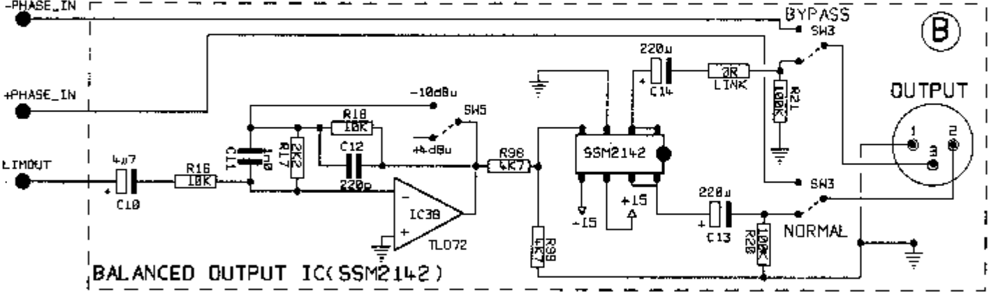
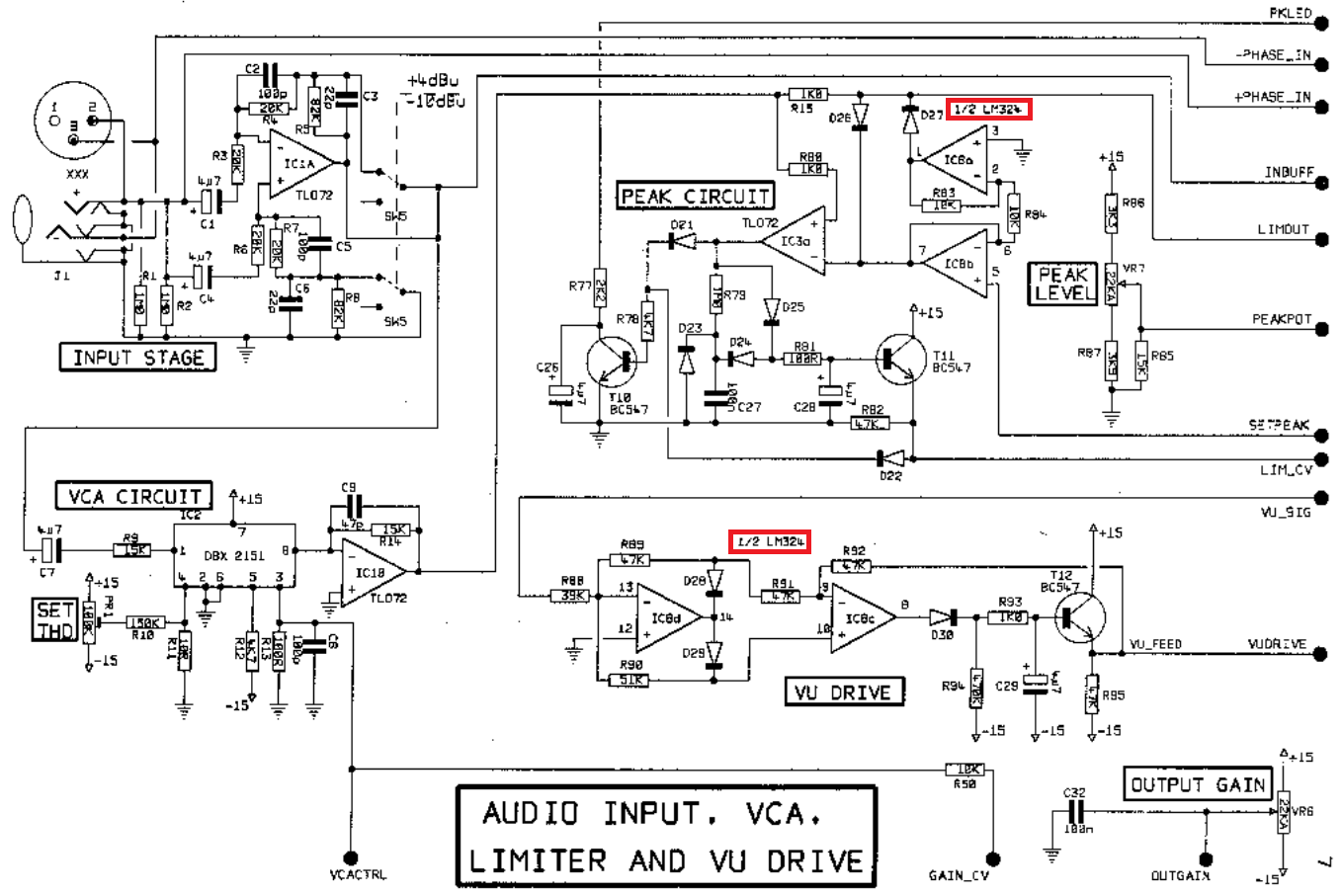
So U21 and U20 seem to be the same, but inverted (by U19). They both share a (+) node so there's some common mode rejection shit going on. And both feed into that 40.2k - 40.2k resister network, so...is the whole point of this amplifier just to have a perfectly symmetric output?
>on circuitlab.com and they paywalled me!!
use LTSpice n00b
>i don't get the mechanism of how it gets doubled.
just basic op amp shit, increase output until reference nodes match
>circuit to be like on page 12 here so that the inverting U19 TL074 can be skipped:
you could, but picrel is cleaner from a design perspective and easier to interpret and troubleshoot
TL074's don't cost shit anyways, so what's the problem
Anonymous
6/2/2025, 11:22:39 PM
No.2921617
[Report]
>>2921620
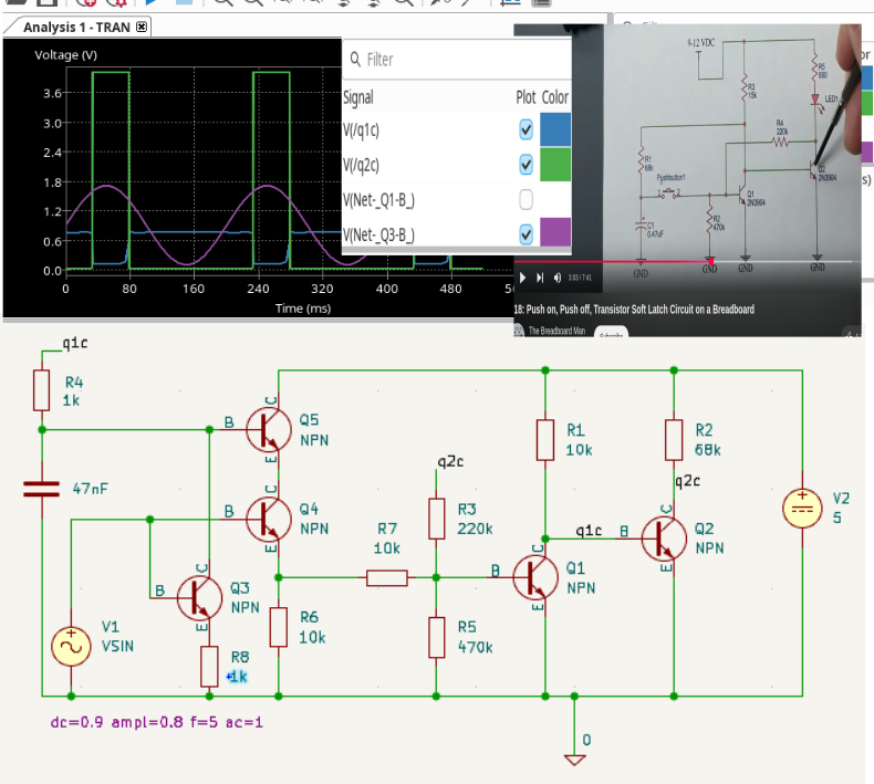
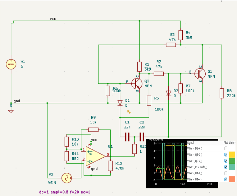
I'm trying to adapt a circuit to take a voltage as input instead of a pushbutton. Directly replacing the switch with a single transistor doesn't work at all and the current simulation has twice as many green peaks as I would like, even though it seems I've replicated the two functions of the switch. Maybe I just need to tune resistor values? Eventually I would use it in a brushed drill battery pack to reverse with every trigger pull.
Anonymous
6/2/2025, 11:36:21 PM
No.2921620
[Report]
>>2921633
>>2921617
Have to ask the dumb question: Why can't you just hook up whatever is generating your "on/off" signal directly to your input?
From what I'm gathering about your use case, I can't see why you couldn't just use a FET to emulate your mechanical switch...
>>2921620
The signal is the same each time but the odd times tell the h bridge to go clockwise and the even times tell it to go counterclockwise. Without the sr latch it can't remember what it was doing so it won't be able to pick the other action.
Kicad's spice has a few different built in fets. I may have tried all of them. I seem to get a 100mV drop across them which might be why it doesn't give the same result as when I use the voltage controlled switch unit, but if I build this I would rather not use a relay.
Anonymous
6/3/2025, 1:29:47 AM
No.2921644
[Report]
>>2921652
>>2921586
>is the whole point of this amplifier just to have a perfectly symmetric output?
yes it's the final output stage
https://technicalaudio.com/pdf/Valley_People/Valley_People_610_Dual_Compr-Expand.pdf
>TL074's don't cost shit anyways, so what's the problem
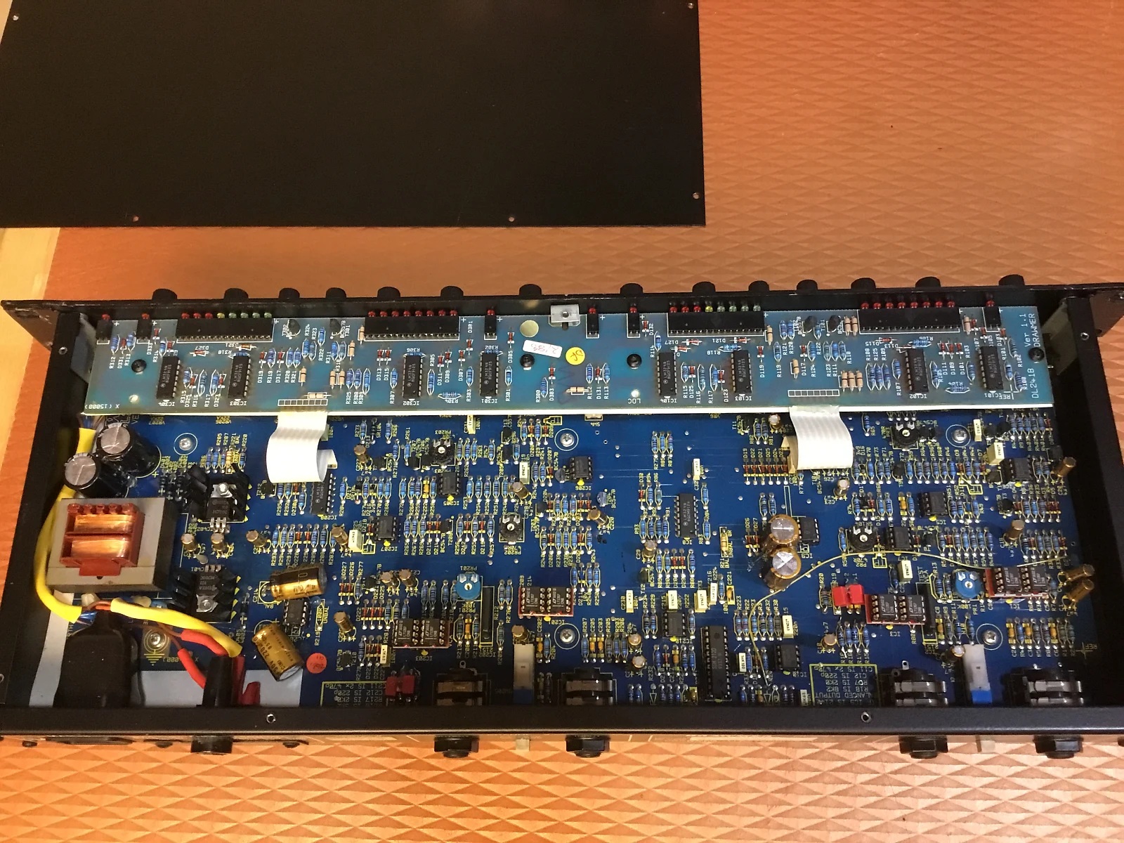
i'm going to upgrade voltage regulators, op-amps and capacitors, the electrolytics might need to be replaced regardless due to age. if the HP design is superior then i thought it might be worth to redo it for marginal noise or THD improvements but i'm not going to bother with it now. for U19 i could use OPA4140 (laser trimmed precision instrument version of OPA1644) to minimize DC offset errors.
now my concern is mainly to check if the new op-amps are legit. i could use two 3V lithium button cell batteries for +/-3V supply to the op-amp, 100 ohm input resistor and 1M ohm feedback resistor for +80db gain (10000x). the input to the op-amp being shorted to ground so that i'm only measuring (low frequency) noise using a sound card to compare against known legit TL074, NE5532, NE5534 etc. with 10000x amplification a 1mV offset turns into 10 volts but i'm hoping an AC coupling capacitor will solve it.
Anonymous
6/3/2025, 1:38:35 AM
No.2921649
[Report]
>>2921916
or does the DC offset come after the amplification, so if the input is shorted to ground and the 80dB gain is done by a single op-amp stage then the resulting offset added by the op-amp is in the order of 1mV or is it 10000mV
Anonymous
6/3/2025, 1:41:33 AM
No.2921651
[Report]
>>2921827
>>2921633
Why not just use a JK-flip-flop logic chip? A D-flip-flop works too, though apparently less reliably. If you can get a Schmitt input D-flip-flop, adding an RC delay between inverting output and input may provide bounce/noise immunity.
74LCV1Gxx series for compactness, or 4000 series for operation without needing a 5V regulator.
Anonymous
6/3/2025, 1:43:27 AM
No.2921652
[Report]
>>2921644
>my concern is mainly to check if the new op-amps are legit
Don’t buy high-grade op-amps from shitholes like aliexpress in the first place for fuck’s sake
Anonymous
6/3/2025, 2:11:27 AM
No.2921657
[Report]
>>2921100
> class d is a special case of a buck converter
Ahh. Great explanation. Thank you. And yes, i was thinking about ali express pam 8403 or the tpa series boards which are somehow cheaper than buying the chip sometimes. I have a bigger sony class d, I’ll take it apart and see what’s inside.
>>2921431
> fuse because no silpad
That’s brilliant, I’ve never seen that before… I’m going to steal that idea immediately. I’m glad I asked. Not sure what to do with that 3-lifetime’s supply of mica to-220 and to-3 insulators though.
>>2921540
>>2921473
Okee dokie, this is what I've come up with. If anyone would please point out my mistakes, it would be appreciated. P type because the switching circuit is normally open, tried to get 5V to the gate. Thanks for the help so far.
Anonymous
6/3/2025, 3:47:05 AM
No.2921686
[Report]
>>2921688
>>2921684
>tried to get 5V to the gate
any particular reason you used a 75 V zener?
Anonymous
6/3/2025, 3:51:02 AM
No.2921688
[Report]
>>2921691
>>2921686
no, other than it was one of the only ones immediately available rated above the 20V of the source, should I be aiming closer to that voltage?
>>2921688
you might want to look up the general principle behind a zener diode. the 75 V figure isnt a maximum rating, its the breakdown voltage of the diode. in your circuit, the diode wont start conducting until theres 75 V across it, which is to say that it will never conduct. if you want 5 V at the gate, youll want to use a 5 V zener.
>>2921691
>>The zener diode is connected with its cathode terminal connected to the positive rail of the DC supply so it is reverse biased and will be operating in its breakdown condition. Resistor RS is selected so to limit the maximum current flowing in the circuit.
Thank you for pointing out my ignorance, the Gth of the mosfet is 3V, so I need to be aiming lower than this?
Anonymous
6/3/2025, 4:07:22 AM
No.2921695
[Report]
>>2921696
>>2921691
>>2921694
Sorry, I've tripped over my own feet. I can use a 5.1V zener and it should all fit.
I think
Anonymous
6/3/2025, 4:13:21 AM
No.2921696
[Report]
>>2921697
>>2921694
>the Gth of the mosfet is 3V, so I need to be aiming lower than this?
not quite. thats Vgs, the voltage from the gate to the source. keep in mind the source of your FET is at 20 V.
>>2921695
>I can use a 5.1V zener and it should all fit.
honestly a 10 V zener would probably be plenty. also, i would personally increase that resistor to like 10 kOhm. it makes the load slower to turn on but you might not even notice. meanwhile a 75 ohm resistor would result in 4 W of extra power draw for the entirety of the time the thing is switched on, which you will probably notice.
Anonymous
6/3/2025, 4:17:18 AM
No.2921697
[Report]
>>2921698
>>2921696
Thank you!
Hopefully I can get the components locally, I'll post a breadboard as soon as I can.
Anonymous
6/3/2025, 4:22:57 AM
No.2921698
[Report]
>>2922771
>>2921697
anytime fren <3
Anonymous
6/3/2025, 6:42:23 AM
No.2921721
[Report]
>>2921827
>>2921633
Post the full circuit. What you're saying doesn't really make any sense. Electrically speaking, there's literally no good way of even telling whether a signal is being switched by a set of contacts or a semiconductor (ignoring stuff that doesn't matter in an abstraction, like switch bounce). The H-bridge or whatever flip-flop/latch thing you've got controlling it has nothing to do with it.
Anonymous
6/3/2025, 6:45:59 AM
No.2921722
[Report]
>>2921684
MOSFET current rating is a function of gate-source voltage, higher is better so long as it’s within the maximum gate-source voltage. Read the datasheet and see what current ratings or on-resistances it gets at different Vgs values. I’d usually go for a Vgs around 9-12V, depending on the FET. Once you know the on-resistance for your chosen gate voltage, you can calculate how much power it will dissipate at your 30A and see if your heat-sink is adequate.
The typical way to use a zener is not in series, but in parallel with the FET, gate-to-source. You’d also need a series resistor to limit current into the zener. Having the zener in parallel with the FET’s gate guarantees that the gate-source voltage never exceeds its maximum regardless of how you drive it, and isn’t as prone to under-voltage conditions forcing your drain-source resistance through the roof and popping your FET.
Also that’s an SPDT switch, it would be just as easy to switch an N-ch MOSFET as a P-ch.
Anonymous
6/3/2025, 6:13:03 PM
No.2921806
[Report]
https://www.youtube.com/watch?v=Xe4u84ufXDU
>High Pass EQ is WORSE than I thought on BASS
OHNONONONONO PHASEFAGS
>>2921651
I didn't know about logic ICs. I may skip them because I already do microcontrollers and that's already too much.
>>2921721
I think the simulation behaves differently because the ngspice voltage controlled switch only has two states whereas the transistor replacement opens/closes more gradually.
I bring up the h bridge because I was asked to post the full circuit.
Anonymous
6/3/2025, 9:37:21 PM
No.2921846
[Report]
>>2921827
> didn’t know about logic ICs
mfw someone tells him about FPGAs
>>2921827
>I may skip them because I already do microcontrollers and that's already too much.
>I do microcontrollers
>a discrete flip-flop is too much
This is your brain on Arduino.
Anyway, after looking more closely at that schematic you posted (I didn't even realize there was supposed to be a latch in there, draw it normal next time), I'm realizing you're actually trying to build a D flip-flop. Unless you're specifically in this for the learning experience, I suggest you just buy a ready-made chip. All you would have to do is just connect your pulse to the CK input and connect not-Q to D.
It's just...I can't figure out why you have this problem at all. If your signal is coming from a digital source, why can't you just make it hold the correct polarity for the duration of the trigger pull? If your signal is coming from a switch, why do you specifically want a "voltage as input"?
Anonymous
6/3/2025, 9:55:55 PM
No.2921850
[Report]
>>2921847
I think it’s a power tool switch that’s already wired to produce voltage directly. But I was under the impression their switches had speed control built in, so who knows.
Anonymous
6/3/2025, 11:48:53 PM
No.2921881
[Report]
>>2921887
>>2921847
V2+ will be the h-bridge ground connected to ground through a 0.25(?) ohm resistor. Q1c and q2c drive the two h-bridge en pins. The brushed drill trigger (switch & potentiometer) is on the motor side of the h bridge. It's not quite right yet because it should flip on a falling edge preferably with a time delay but I'm optimistic I can fix that.
I don't mean that I can't figure out a flip flop IC or that it isn't the best part for the job. I mean that I have a tendency to hoard so I try to use what I already have.
Anonymous
6/3/2025, 11:59:39 PM
No.2921887
[Report]
>>2921881
You can probably make a master-slave T-FF using a pair of comparators and maybe some diodes, plus passives. Surely you have a few LM393s, no?
Anonymous
6/4/2025, 12:32:18 AM
No.2921894
[Report]
>>2922100
If a diaphragm pump pumps peak 20L/min and 4bar static pressure with water, would you assume something ten times as viscous to get peak 2L/min and still 4bar static pressure? Assuming the motor doesn’t overheat, that is.
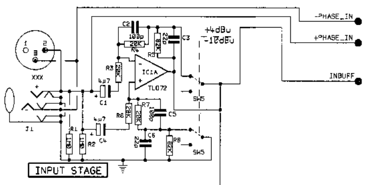
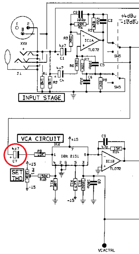
220uF AC coupling cap with 100kOhm resistor. 0.0072Hz cutoff frequency. based or overkill, not necessary when used with 10kohm impedance load instead of 600ohm? this is drawmer DL241 (XLR version) from 1991.
Anonymous
6/4/2025, 3:28:43 AM
No.2921916
[Report]
>>2921919
>>2921649
The offset is on the input yeah, so yeah the more gain the worse it will be.
>80dB gain is done by a single op-amp stage
lmao good luck
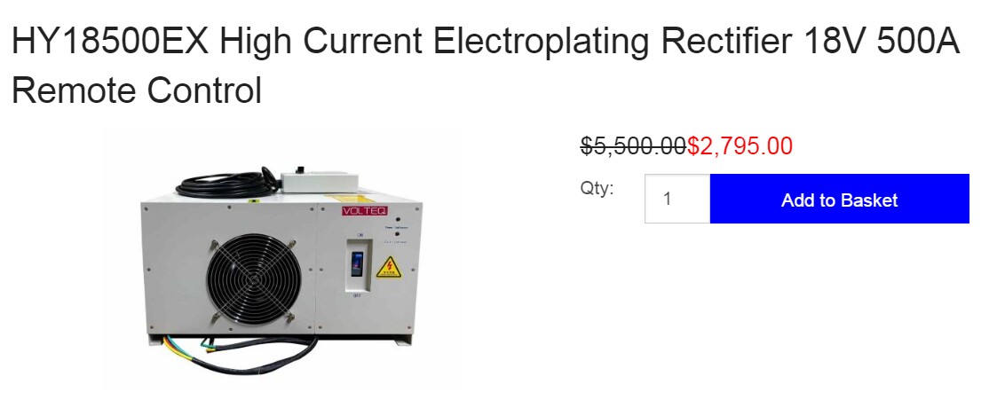
>>2920495 (OP)
I want to do some experiments with electroplating, what tools do I need, and how cheap can I get them? I don't know much about electronics.
Anonymous
6/4/2025, 3:55:26 AM
No.2921919
[Report]
>>2921916
they're supposed to have enough open-loop gain, i just want to check the low frequency noise because the noise level narrows it down a lot, even OPA1612 and OPA1642 have distinguishable noise levels from each other and of course the others like TL072 NE5532 NE5534. some chinese sellers have been known to sell legit op-amps, people have checked the silicon dies with a microscope.
Anonymous
6/4/2025, 5:08:37 AM
No.2921925
[Report]
>>2921932
>>2921907
>based or overkill
10K is not the load impedance, you silly goat
load impedance is determined by whatever is connected to the XLR plug
>>2921918
>experiments with electroplating
- DC low-voltage power supply, the more current it can supply, the better
- very thick cables
- tank + chemicals
Anonymous
6/4/2025, 5:33:27 AM
No.2921931
[Report]
>>2921928
>500A
>$2795
Are you chrome plating Mongoose BMX bike frames? lmao
Anonymous
6/4/2025, 5:34:42 AM
No.2921932
[Report]
>>2921925
dude, i know. 10-20k is common in modern pro audio, 600 ohm is legacy line level. some outboard gear can switch between 600 ohm and 10k input impedance. reasons to have a much higher capacitance than what is practical to have with a film capacitor is to reduce output impedance to better match a low input impedance like 600 ohm, to improve fidelity with low noise and to move the cutoff frequency closer to zero for minimal fuckery with the audible frequency response and phase. most other outboard gear uses 100uF and this uses 220uF. bipolar 220uF isn't prohibitively expensive but do i really need it. is it going to be a nuisance in case there is DC in the signal and it needs a long warm up period after turning it on to filter out the DC offset. is it significantly worse to go with 100uF or dual 100uF in parallel instead of 220uF.
Anonymous
6/4/2025, 7:34:39 AM
No.2921950
[Report]
>>2922041
>>2921907
It would take minutes for the DC to disappear. You’d be better off stacking a 1k/220u filter into a 10k/22u filter into a 100k 2.2u filter for faster rolloff. Probably still shitty phase shift though, but stop trying to fix things with a bigger hammer.
>>2921918
Goeffery Croker on YouTube has a video on copper and nickel electroplating, and Scrap Science has some great videos on electrochemistry in general.
You’ll want a CC/CV PSU at minimum, but PWM capability would help too since pulsed electrolysis is a thing. Or even a fully programmable PSU. There are cheap and diy options, but whatever you pick should be able to reliably run continuously for weeks on end.
Anonymous
6/4/2025, 6:59:23 PM
No.2922041
[Report]
>>2922116
>>2921928
I only want to experiment with electroplating things at most a couple inches across, I hope I don't need to a 2000 dollar power supply for that
>>2921950
>Scrap Science
already been watching him
Pulsed electrolysis sounds cool
What websites should I search for a power supply on, Ebay, Aliexpress, Amazon, Craiglist?
Anonymous
6/5/2025, 12:06:07 AM
No.2922100
[Report]
>>2921894
I would guess 4 bar too, but 2 lpm is suspect. I think you need another data point because the motor's own no load speed leads to a parameter that contributes to the pump curve, but that contribution won't change with viscosity.
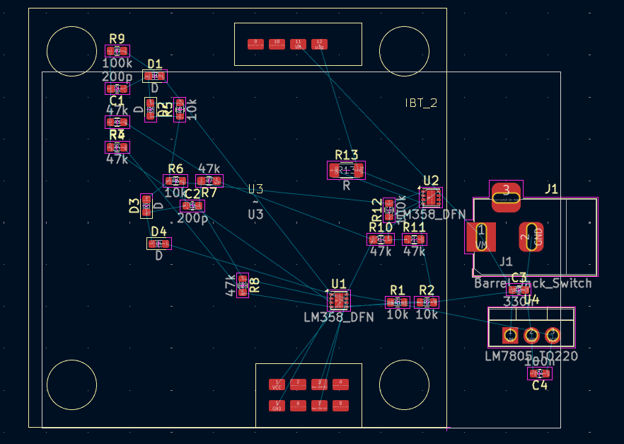
What is the layout algorithm when mixing smd and tht on a board with plated holes? For example here I could start everything smd and then whenever I need a short trace one component could be changed to the tht to get the wire. There must be a heuristic for which net to start with and which component.
Anonymous
6/5/2025, 1:00:29 AM
No.2922107
[Report]
>>2922103
The "algorithm" is to do everything in SMT to reduce part count and assembly complexity, and the fab house can deal with the extra difficulty in making the board.
More practically, if you're doing this for yourself, it's kind of a "do whatever you want" situation. Personally, I usually just start with placing whatever parts that are required to be in a specific location (which you've done, it looks like). Then, just work backwards from there, placing whatever components are most closely connected to those in place, then those connected to those, and so on. Making exceptions along the way for nets that must be routed a specific way for signal/power/grounding reasons, of course.
>and then whenever I need a short trace one component could be changed to the tht to get the wire.
Not sure why you'd do this on a board with plated holes. This is mostly a technique used for homemade boards, where through-holes have to be connected to opposite sides manually, or single-sided boards, where it can save a jumper wire connection.
>>2922041
>What websites should I search for a power supply on, Ebay, Aliexpress, Amazon, Craiglist?
2nd hand is always something to look out for. Personally I just bought an SK90 DC-DC control converter module and a USB-PD trigger board to power it from, though not specifically for electrolysis. I doubt it can do pulsed stuff, but the graph feature is nice looking. Just arrived today, I'll be CADing out an enclosure to 3D print.
>>2922103
Make sub-modules of parts that need to be close together, then see how you can cram those sub-modules together. Just the same as any other board layout. Start with any components that have fixed locations, like edge connectors and heat-sinks and mounting holes and such. Then pick the component that's connected to the most shit (e.g. main microcontroller or high-pin-count connector) and place all the passives and other supporting components with respect to it. Then have fun rotating and translating that component around to fit best on the board.
If you're struggling with a single-sided design, then it's the same, but with more trial and error. Take screenshots of your progress before you revert and try another layout. Unless your board connectors can just be single wires, it's probably not possible to solve a dual-op-amp topology.
You better not be hand-soldering those DFNs.
Anonymous
6/5/2025, 2:07:36 AM
No.2922121
[Report]
>>2922116
>You better not be hand-soldering those DFNs
They did seem smaller than I expected. I'm actually using soic-8 (lm358dr) either with an adapter board or maybe this time I'll bend the even numbered legs up.
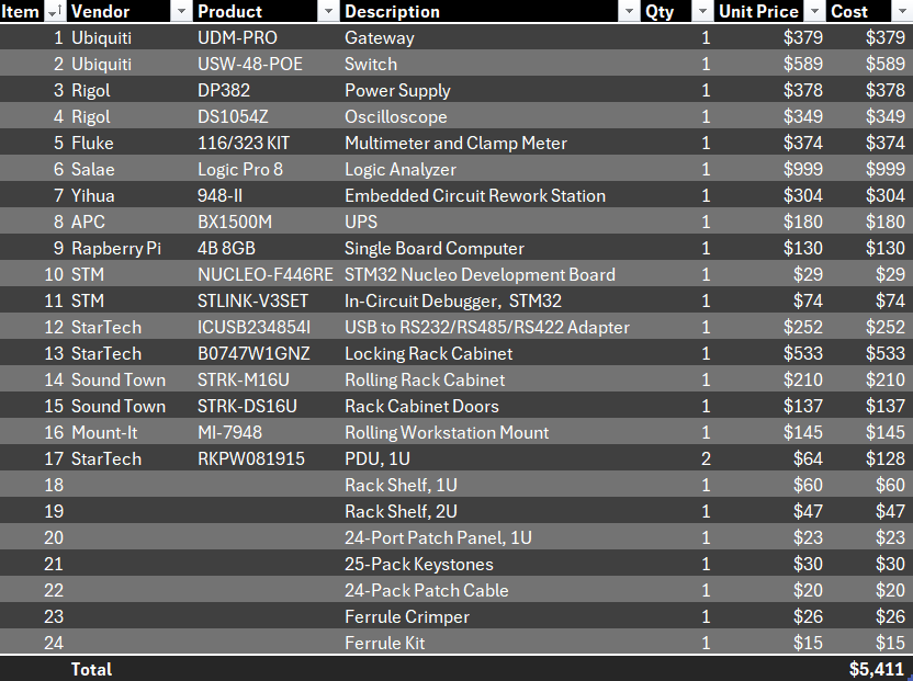
Due to reasons, I have thousands of dollars specifically (and not usable for any other purpose) to set up a home development lab for embedded systems experimentation. My particular context is space systems engineering, so think RS-422 and RS-485 devices run off of an SBC, using real-time embedded software like nasa cFS.
I don't know what would be useful I need so I've just shotgunned it.
Missing anything major?
Anonymous
6/5/2025, 1:20:44 PM
No.2922176
[Report]
>>2922175
(some stuff like breadboards and dupont wires and bulk resistors etc i've already got).
for the soldering station i was just trying to make sure my bases are covered.
Anonymous
6/5/2025, 5:13:51 PM
No.2922205
[Report]
>>2922240
>>2922175
Just one dev board? LOL.
If you want to fuck around, you might want to get an FPGA board or two. My old USB -> RS232 converter is FPGA based (I think it was for palm pilots)
> USB -> RS485 etc
You need to build shit that’s useful, like ethernet to rs485 since you’ve got poe switches and whatnot.
You should probably get a bench magnifier of some kind, especially nowadays. I had to look up what a DFN even was.
>>2922116
avoid digital ones, if possible.
Anonymous
6/5/2025, 8:09:08 PM
No.2922240
[Report]
>>2922243
>>2922205
the actual boards and sensors are so dirt cheap i'm not really including them in this rollup, just the actual test equipment
but i'm not just fuckin around, i work on satellites and it's very common to have a "flatsat" for ground testing software before pushing it to the vehicle.
i work fully remote, however, and while this isn't a huge part of the job and while i *can* VPN into the flatsat lab, there's no substitute for being able to actually fuck with things in person. good career development for me.
Anonymous
6/5/2025, 8:29:27 PM
No.2922243
[Report]
>>2922265
>>2922240
What country do you live in? Is this an academic exercise for college credit or something else?
Anonymous
6/5/2025, 9:29:00 PM
No.2922255
[Report]
>>2922116
>You better not be hand-soldering those DFNs.
Anonymous
6/5/2025, 10:16:21 PM
No.2922265
[Report]
>>2922269
>>2922243
US; i work as a space systems engineer and am also getting my masters' in space systems engineering. So it's academic and also career development.
Anonymous
6/5/2025, 10:37:57 PM
No.2922269
[Report]
>>2922403
>>2922265
man, i envy you i am unemployed and kinda the same background, europe tho
(i doubt that i will have problems finding a job after i get one back, but right now i am in a stupid position)
as said get some microscope too for the soldering jobs
i mean i could proposed radio equipment, or cameras but i think you have that covered no?
maybe a network analyzer?
a small vaccum chamber to test the thermal characteristics of devices in vaccum?
those are for the experimental part, but i doubt you would go that far
and of course a couple of screens to larp as being in a track station with shit like picrel open
(joystics to play ksp too)
Anonymous
6/5/2025, 11:14:19 PM
No.2922276
[Report]
>>2921569
if it's run off a bipolar +/- 12V supply then this won't be an issue? apparently phase reversal occurs with tl071/2/4 for volts within a couple volts of the negative rail.
Anonymous
6/6/2025, 12:06:13 AM
No.2922286
[Report]
>>2922324
Noob here. I just breadboarded a boost converter and I was playing with it, trying different indicators and capacitors and driving frequencies. I have a known load and input voltage (12V DC fan and an old wall wart) and I'd like to know how to calculate the optimal parameters (inductor, capacitor, driving frequency, duty cycle).
Anonymous
6/6/2025, 12:11:47 AM
No.2922288
[Report]
>>2922175
I’d get MCUs (on dev-boards) that can speak industrial protocols directly (with a transceiver chip) like CAN, Ethernet (plus PoE), RS485, etc. and then get those transceiver chips (on breakout boards), two or three of each so you can speak MCU-toMCU. Make sure you have a way of sending and receiving arbitrary packets of those via computer with a USB converter, but for an SBC there may be more direct methods via GPIO than using USB. And also ensure your logic analyser is fast enough and is capable of reading them (e.g. +/-12V signalling).
Also a LimeSDR.
Anonymous
6/6/2025, 3:42:09 AM
No.2922324
[Report]
>>2922660
>>2922286
Ok so the peak current in your inductor is a linear function of the transistor on-time, the input voltage, and the inductance: V = L*dI/dt. The energy stored in the inductor each cycle is E = 0.5*L*I^2, where I is the peak current from the earlier equation. So the maximum power output will be a function of that energy per cycle, multiplied by the cycles per second. The off-time should need to be long enough for the inductor to empty itself in order for you to get that peak power output though, which also follows the V = L*dI/dt equation, but with V and I scaled inversely by the multiplication ratio (e.g. 2*V_in, 0.5*I_in_peak). Capacitor choice just dictates the output ripple.
Seems like modern GaN DC-to-DC converters can get up to 15kW/L, resonant/ZVS converters can be similar. According to google AI at least, because I can’t find actual results from a quick search, they’re probably in studies on Researchgate. 60W in 4 cubic centimetres is probably small enough for a 3.7V lithium-ion soldering iron using common cartridge tips, no? Especially since you can probably shrink the input and output caps. Not sure whether high-frequency magnetics and GaN transistors is the best way for LVDC conversions though, maybe metglas magnetics at a lower frequency could be better. Or if a GaN ZVS would be even better still.
Anonymous
6/6/2025, 5:12:38 PM
No.2922403
[Report]
>>2922454
>>2922269
if you're in yurop i'm CONSTANTLY seeing linkedin posts for this guy trying to hire space systems engies for luxembourg.
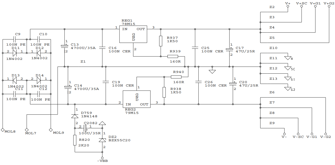
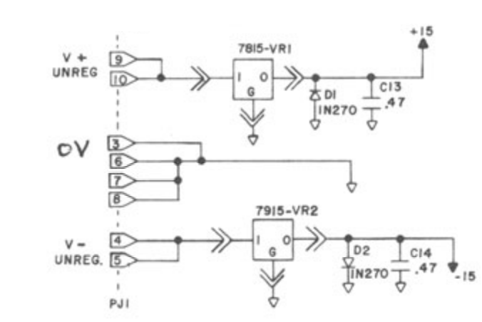
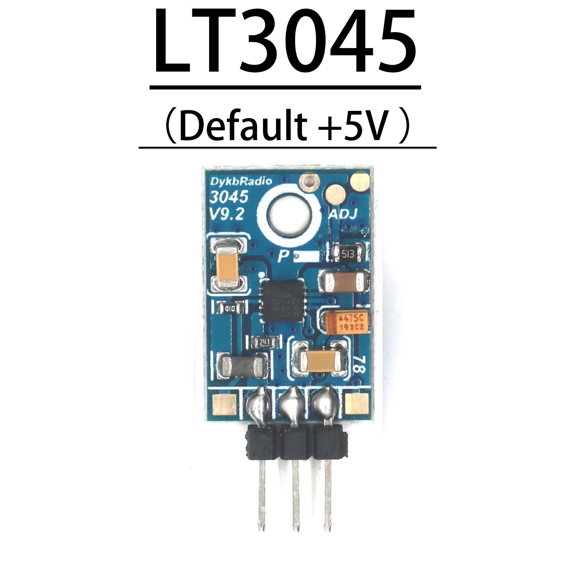
what are general design principles, rules of thumb to estimate if a PSU filter capacitor can be a low ESR polymer capacitor without causing stability issues? the 4700uF in pic rel can be polymer? i'll replace the 78M15 and 79M15 voltage regulators with LT3045/LT3094 modules which hopefully have the stabilizing capacitors integrated (i can't read the SMDs off of pictures except one of them is the correct 4.7uF for minimizing noise). can the 47uF be low ESR polymer or is it better to use audio grade bipolar electrolytic for minimizing leakage current?
Anonymous
6/6/2025, 6:45:26 PM
No.2922415
[Report]
there's a toroidal transformer that's not shown in the schematic
>>2922353
> GaN
Are you building a satellite or something?
I don’t even see the real need for SiC devices… it’s kind of a fad.
Bipolar devices didn’t disappear with the introduction of MOS devices, and the bipolar is one of the more robust technologies.
Those new active rectifiers are pretty neat though, but do seem fragile.
Anonymous
6/6/2025, 9:58:58 PM
No.2922454
[Report]
>>2922403
thanks man, will follow him
>>2922449
smaller shit that needs to be portable or on a vehicle
Anonymous
6/6/2025, 10:59:33 PM
No.2922468
[Report]
>>2922529
>>2922353
> ZVS… 500 kHz … > 1 MHz at 15 kW…
Holy radio interference batman!
Please don’t unintentionally cook your spleen while standing next to it.
>Voltage regulators are designed to maintain a stable output voltage, but they generally do not block current transients. Instead, they aim to respond to changes in load current or input voltage by adjusting their internal circuitry to maintain the desired output voltage. They often include current limiting features to protect against overcurrent conditions, but they do not typically filter or suppress current spikes.
so the 47uF should be low leakage current
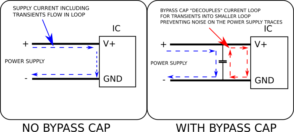
what about the 100nF, i haven't read the article below yet, is it best to leave them alone in the existing design or mod them
https://codeinsecurity.wordpress.com/2025/01/25/proper-decoupling-practices-and-why-you-should-leave-100nf-behind/
Anonymous
6/7/2025, 2:04:52 AM
No.2922517
[Report]
>>2922521
>>2922510
holy shit nigger, reply to your own fucking posts. im not going to read up in the thread trying to figure out which posts are yours for the privilege of helping your dumb ass.
Anonymous
6/7/2025, 2:22:47 AM
No.2922521
[Report]
>>2922517
>implying you know how to help
>>2922414
not sure why these are 47uF, maybe because this one does have fat inductors to add audible bass harmonics as an effect. the equivalent in pic rel are just 0.47uF, if bigger is better because low impedance then what if i put 4.7uF film caps instead of the 0.47uF
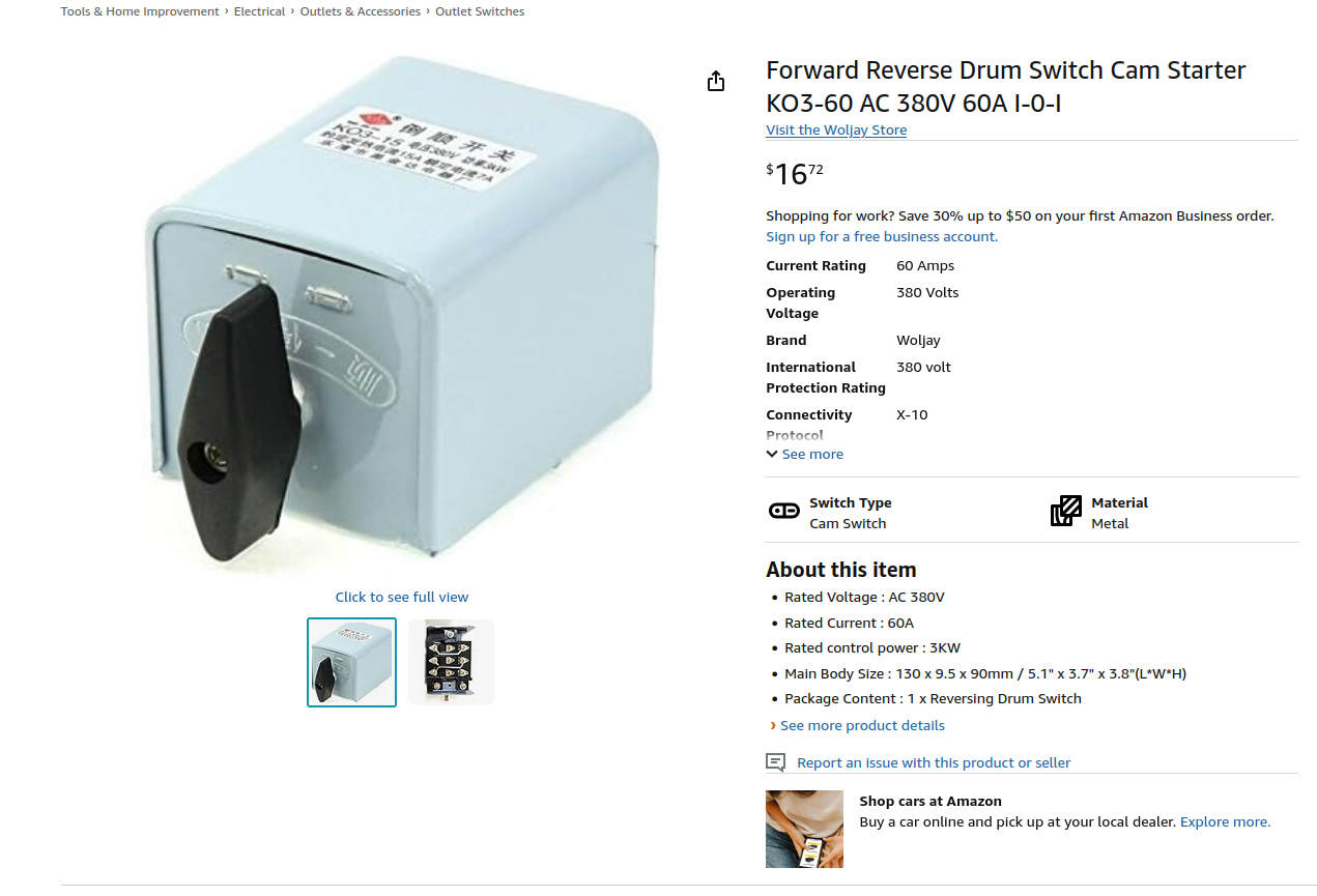
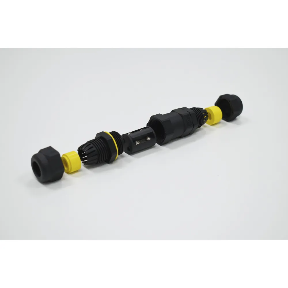
I need a new switch for an old 1.5hp bridgeport mill would this work for 220v 3 phase?
OEM is like 200-300 dollars I wouldn't mind paying a little more but thats retarded
Anonymous
6/7/2025, 2:52:18 AM
No.2922529
[Report]
>>2922564
>>2922449
I already said, I’m looking into designing a battery-powered soldering iron that isn’t cucked by trash tips and low-power output. 45W with temperature control would get you pretty decent battery life at standby if the tip is nice and compact, like a T245 or similar.
GaN is taking over the consumer AC-to-DC market because it can be smaller and more efficient for the same power output. The lack of the body-diode means you don’t have limitations from reverse recovery to worry about, and can switch faster with smaller inductors and capacitors. Even cheap shitty USB PD bricks from china are using this technology, because it’s cost effective and here to stay.
SiC is for higher voltages, they’re replacing IGBTs. No real reason to use SiC if you’re operating below 600V.
>>2922468
Don’t worry, it’s sinusoidal (no square harmonics) and contained within a toroid.
>>2922510
Read datasheets and appnotes to figure out what kind of capacitor ESR they’re expecting.
Anonymous
6/7/2025, 3:46:38 AM
No.2922544
[Report]
>>2922565
>>2922528
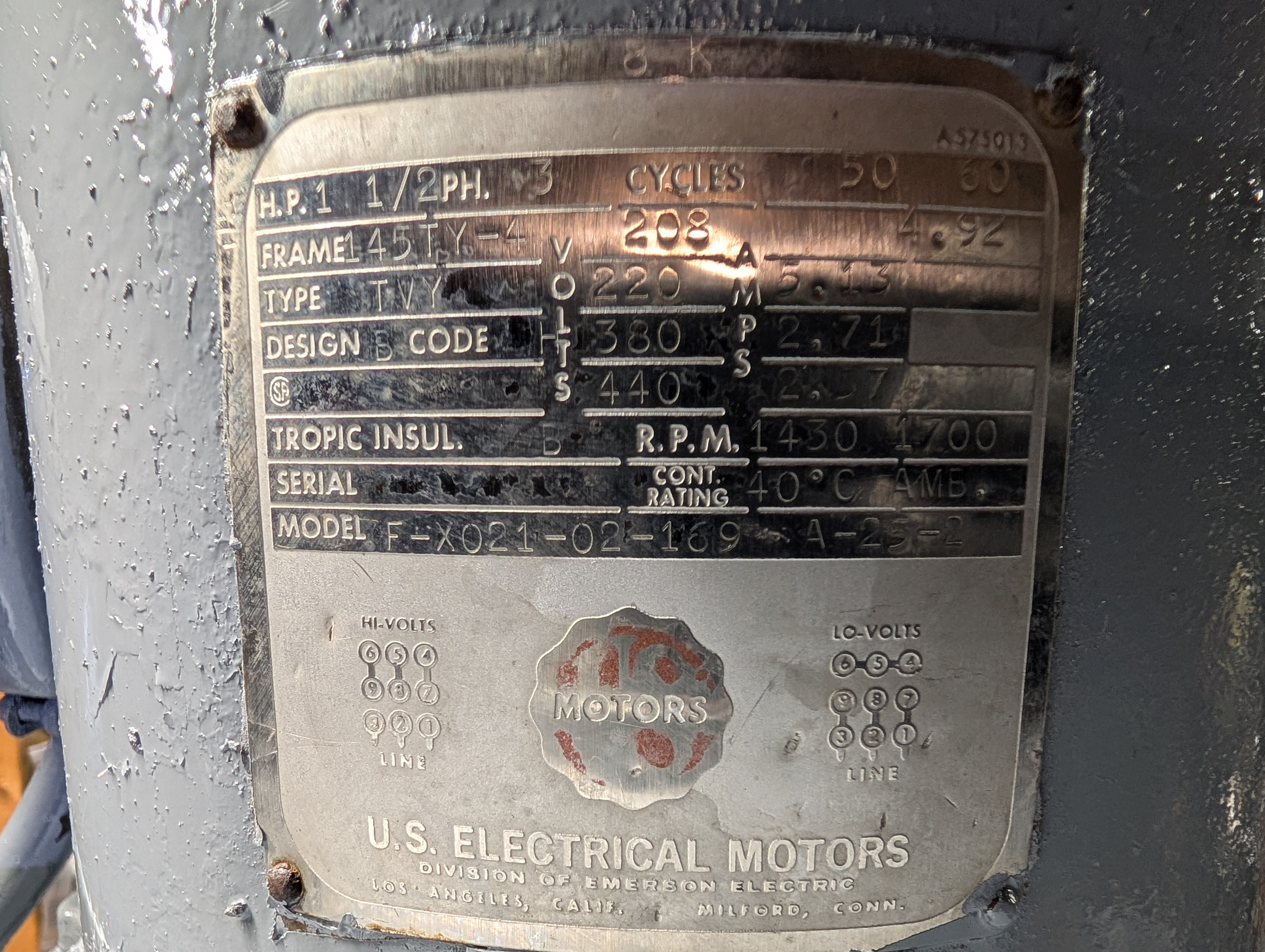
here is motor info
Is there a better option?
Anonymous
6/7/2025, 5:43:38 AM
No.2922564
[Report]
>>2922573
>>2922529
>Read datasheets and appnotes to figure out what kind of capacitor ESR they’re expecting.
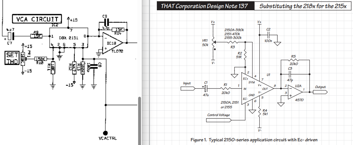
there's no such detailed information, at best you get schematics showing the "what" and not the "why". i can only speculate that some designs are archaic, for example if a 1uF electrolytic capacitor was used because 1uF film caps weren't available/affordable at the time. they generally use bog standard op-amps like TL072 and NE5532. in some cases the VCA is somewhat documented but there aren't every specific hints and the VCA is just one minor component and the main thing is the surrounding circuitry. in some cases the VCA is fully proprietary. example VCA:
https://www.thatcorp.com/datashts/THAT_2180-Series_Datasheet.pdf
some of them don't document the PSU as part of the schematic but they all use pretty similar linear PSUs with a transformer, rectifiers, 1000/2200/4700uF smoothing capacitors and probably 47/100/470nF bypass capacitors. there's got to be a general line of thinking that the smoothing capacitors maybe can be polymer caps just that they went with electrolytics because that was what was available at the time. or maybe the low ESR or the leakage current of the polymer caps can be problematic but what are the things to look for to know if that's a real issue or not. i've seen a comment where someone had modded a vintage yamaha synth and messed it up with severe oscillation but there's very little info on these other outboard gear.
Anonymous
6/7/2025, 5:47:27 AM
No.2922565
[Report]
>>2922569
>>2922528
>>2922544
Your motor draws <5A, that switch is allegedly 60A which seems overkill but they are chinese amps so it's probably just right. The switch appears to be 3 pole from that grainy screencap so yes, it would work.
Anonymous
6/7/2025, 6:30:31 AM
No.2922569
[Report]
>>2922565
Yeah I was kind of looking around and found an aliexpress listing with the same part number but the spec sheet is in chinese I used google translate but idk what the "agreed heating current" and "agreed working current" means. I guess I will probably just go ahead and get it I was looking at a Dayton 2X441 switch but its about 4 times more expensive
https://www.aliexpress.com/i/3256807459020290.html
Anonymous
6/7/2025, 6:54:46 AM
No.2922573
[Report]
>>2922564
>1uF film caps weren't available/affordable at the time
1uF MLCCs have been around since the 70s or 80s, they’re also good enough for any power supply filtration.
Buy some of the components and test stability with different capacitors and varying current draws.
Anonymous
6/7/2025, 7:16:36 PM
No.2922660
[Report]
>>2922324
Thanks. Since your post I did some research and found a bunch of nifty equations that derive from what you wrote. One thing I wasn't able to find an explanation for, despite finding the equations and their derivation, is the choice between CCM and DCM.
Anonymous
6/7/2025, 9:02:23 PM
No.2922679
[Report]
>>2922730
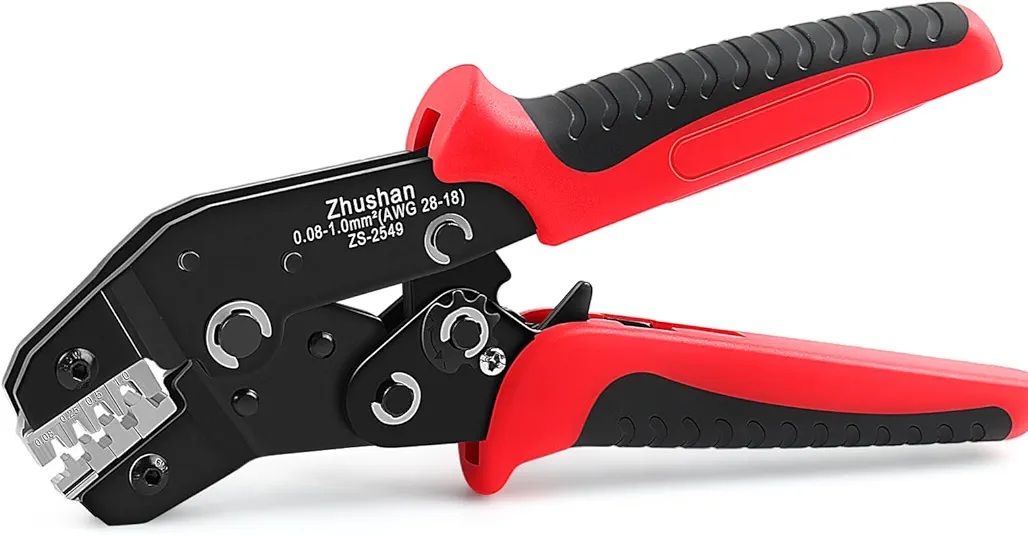
Are genuine terminals but Chinese crimp tools enough to not burn something down?
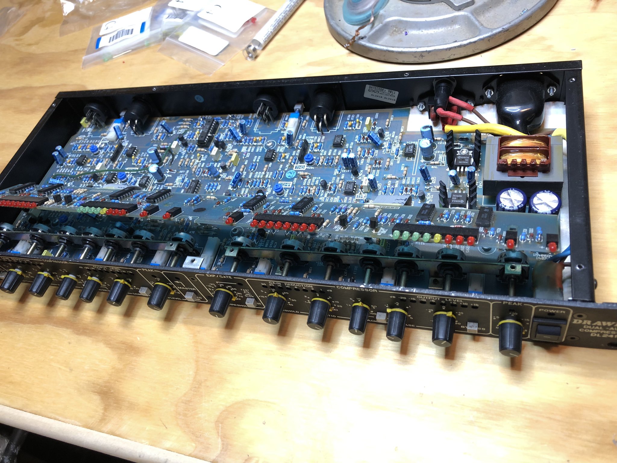
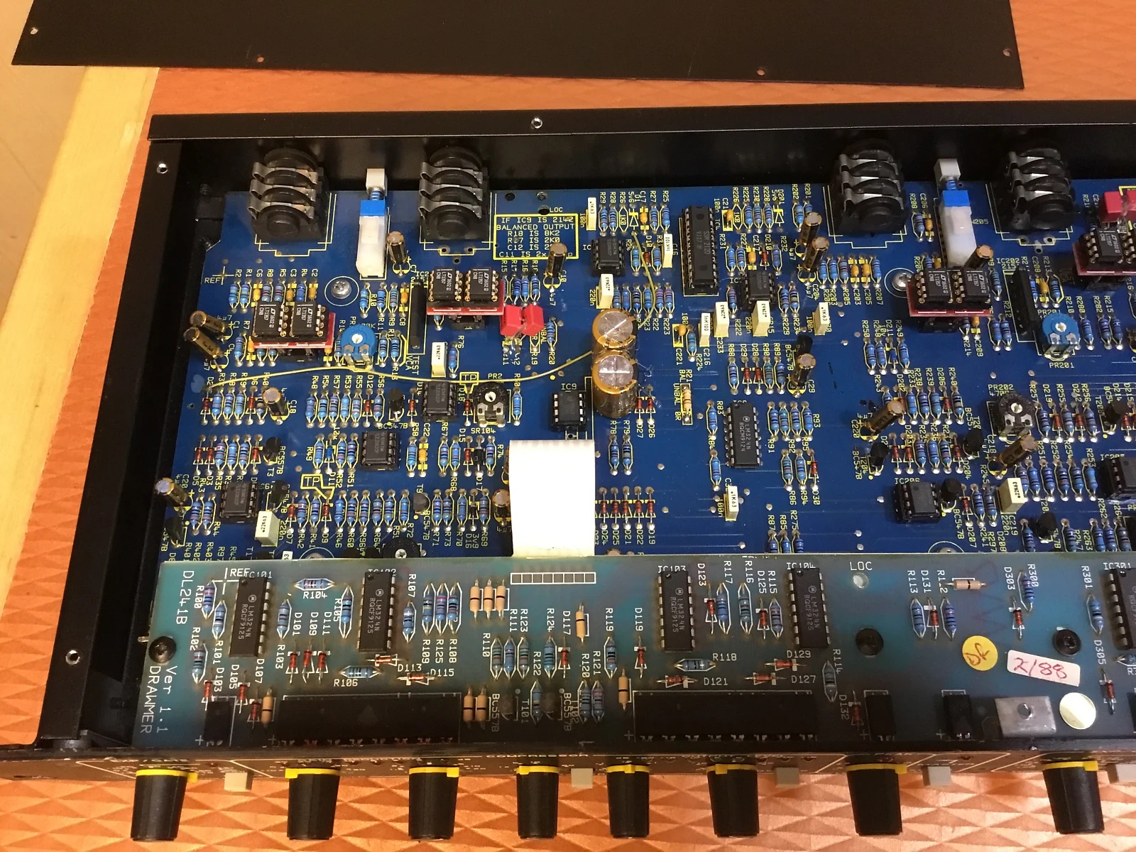
>Drawmer DL241
>I have one on the bench now. It's like the 166 but has a manual attack-release switch and a balanced output pcb. It uses a SSM2120 RMS detector rather than the dbx part. The power supply is current starved with a tiny pcb mounted power transformer and 4.7 uf secondary filter caps.
>I install a torroid power transformer to supply the needed current and large 4700uf mains caps. Secondary caps are 1000 uf. Then they work well and quietly.
i don't have a PSU schematic for the drawmer but assuming it's similar to
>>2922414 does he mean that the 1000uF caps go after the voltage regulators where the 47uF caps are?
Anonymous
6/8/2025, 1:51:11 AM
No.2922730
[Report]
>>2922679
>Chinese crimp tools
your paranoia will never let you sleep until you buy one made in USA UK or Germany
i think the stock PSU has a split bobbin transformer with 2200uF caps
Anonymous
6/8/2025, 2:06:27 AM
No.2922734
[Report]
>>2922738
>>2922728
>does he mean
that's what he means
and the important life lesson there is not to fixate on simple-minded details like that
if a chosen value can vary by 20 times without harm, then it had very little importance to begin with
i'll bet $1B the unit's performance would show no obvious change even if you removed those caps entirely
Anonymous
6/8/2025, 2:16:39 AM
No.2922738
[Report]
>>2922734
https://www.youtube.com/watch?v=UTetQhGyUVg
23:15
>audio amps have massive capacitors
unless you buy the latest and greatest gear that costs thousands you need to service them like at least replace the electrolytics and why not put some nice stuff in there while you're at it. there are companies that specialize in these types of mods. the average musicfag really sucks they think it's obsolete boomer technology that doesn't even sound as good as a digital software plugin but you can make it sound even better than a new $$$$ piece of hardware if you're not afraid to pick up a soldering iron.
Anonymous
6/8/2025, 2:23:14 AM
No.2922741
[Report]
>>2922757
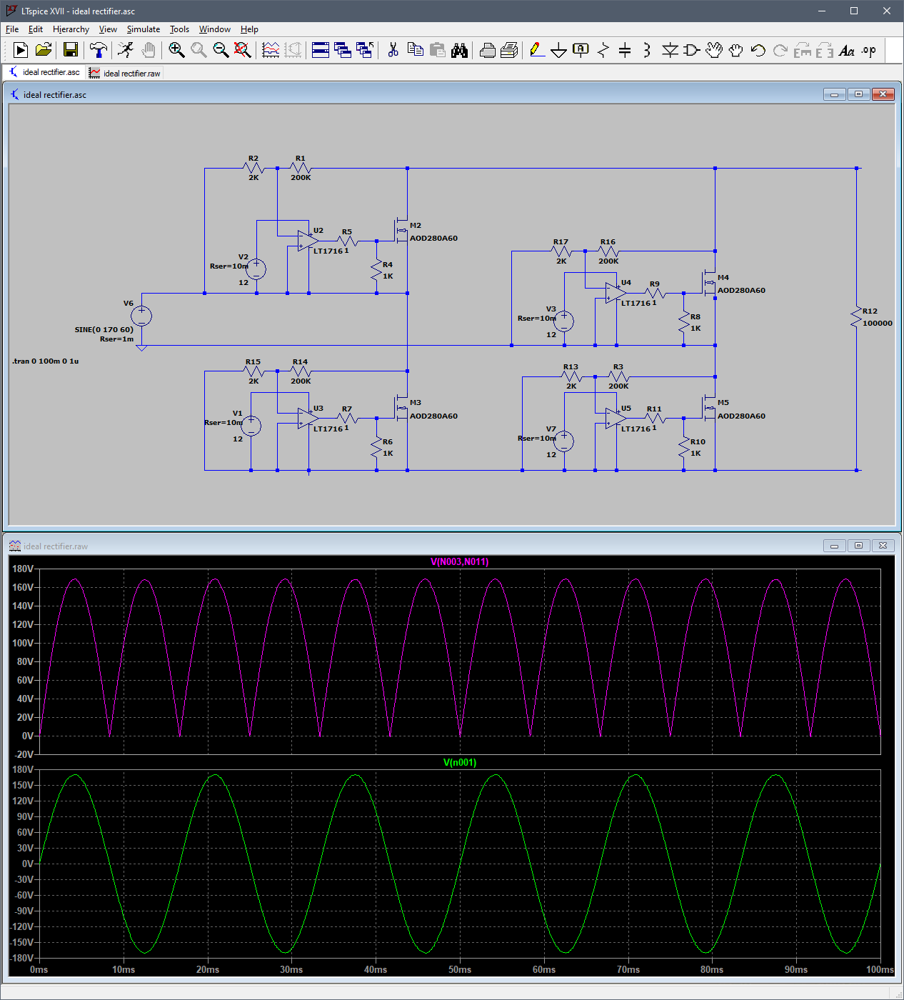
for the sake of autistic tinkering, let's say i wanted to build a discrete ideal rectifier (from mains AC) with four floating charge pumps and four comparators like pic related. in reality i would probably use something cheaper like an lm339 and a 555 charge pump.
would this actually work or am i overlooking some critical aspect of 'real life' that would make this violently explode in my face?
Anonymous
6/8/2025, 3:46:27 AM
No.2922757
[Report]
>>2922741
Your test load seems kind of high.
I believe, if I were building it, I’d just want to make sure all the mosfets fail “open” and they never all turn on at the same time.
Anonymous
6/8/2025, 3:56:43 AM
No.2922759
[Report]
>>2922528
> woljay
I love me some of that woljay brand. I think they’re the defacto standard.
> specially made display switch has a gap in the sheetmetal at the top to help transmit the arc through your hand
… but helps for ventilation,
Good luck, anon.
Anonymous
6/8/2025, 4:00:45 AM
No.2922760
[Report]
>>2922766
https://www.diyaudio.com/community/threads/is-bypassing-psu-capacitors-effective.126697/#post-1566310
>For example, a small film capacitor in parallel with an electrolytic capacitor not having high ESR will actually result in higher overall output impedance, ringing and very bad performance in the low Mhz range.
https://www.diyaudio.com/community/threads/is-bypassing-psu-capacitors-effective.126697/#post-1566979
>This is a more or less optimum solution with class-D and SMPS in mind, the most demanding applications. Two 100nF chips are required in order to get low impedance up to 50Mhz. Also, five 100nF film capacitors with 1ohm resistors in series are required to tame the resonant peak around 3Mhz (SMD chips are too expensive to use so many).
not even mentioning larger film caps like 1.0uF-4.7uF because they are bad because of inductance at high frequencies or just expensive for whatever industrial shit they were doing in 2008?
https://www.diyaudio.com/community/threads/paralleling-film-caps-with-electrolytic-caps.106648/post-1299939
>Some folks avoid the whole mess by running a few smaller electrolytics in parallel instead of a single large one, which increases capacitance while also decreasing ESR and ESL. It's a neat trick if you have the room.
sounds good if it's that simple
https://www.diyaudio.com/community/threads/paralleling-film-caps-with-electrolytic-caps.106648/post-1300953
>I'd recommend a larger poly cap, something like 0.47 uF to 1.0 uF. Bypass ratios of 1500:1 make me nervous about parallel resonances.
so now in 2025 it's trivial to use 1.0uF-4.7uF film caps
https://www.psaudio.com/blogs/pauls-posts/bypassing-caps
based boomer
Anonymous
6/8/2025, 4:41:32 AM
No.2922766
[Report]
>>2922760
> based boomer
Not really. I ran across some of his videos a while back and he made some pretty strange terminology mistakes that made me cringe.
Seems a lot more like a radio-shack tier salesman.
>>2921698
>>2921684
Okay, so far the circuit works as intended, but only if I omit the 10V zener and replace it with a short. I've checked and double checked the polarity of the diode and it seems fine, so I'm guessing it is in the design? The only other difference is I'm using a light bulb as a load, not the power tool, but that shouldn't matter...
My calculations were done from the following abstract:
https://www.electronics-tutorials.ws/diode/diode_7.html
Anonymous
6/8/2025, 11:56:19 AM
No.2922795
[Report]
>>2923138
>>2922771
Not the anon who originally helped you but can you measure the gate-to-source voltage with the zener diode in? In theory if it is a 10v zener and your supply is 20v that would be 10v Vgs which should be enough. I'm guessing your issue is that the MOSFET is not turning on properly because it's not getting enough voltage from gate to source. Replacing the zener with a short brings the gate right down to 0v which will make the gate to source voltage equal to the whole supply voltage which can be as high as 20v in your case.
Also is your max battery voltage actually 20v exactly or is it 21v? If you omit the zener diode you will be risking blowing up the MOSFET gate because the MOSFET in your schematic is rated for 20v gate to source. I would personally use a voltage divider instead of a zener. A 10k resistor from the positive rail to the gate in series with a 1.5k resistor from the gate to the negative supply rail would drop a few volts and prevent you from exceeding the max Vgs rating while still giving the MOSFET adequate voltage to turn on fully .
Anonymous
6/9/2025, 2:30:57 AM
No.2922916
[Report]
>>2922921
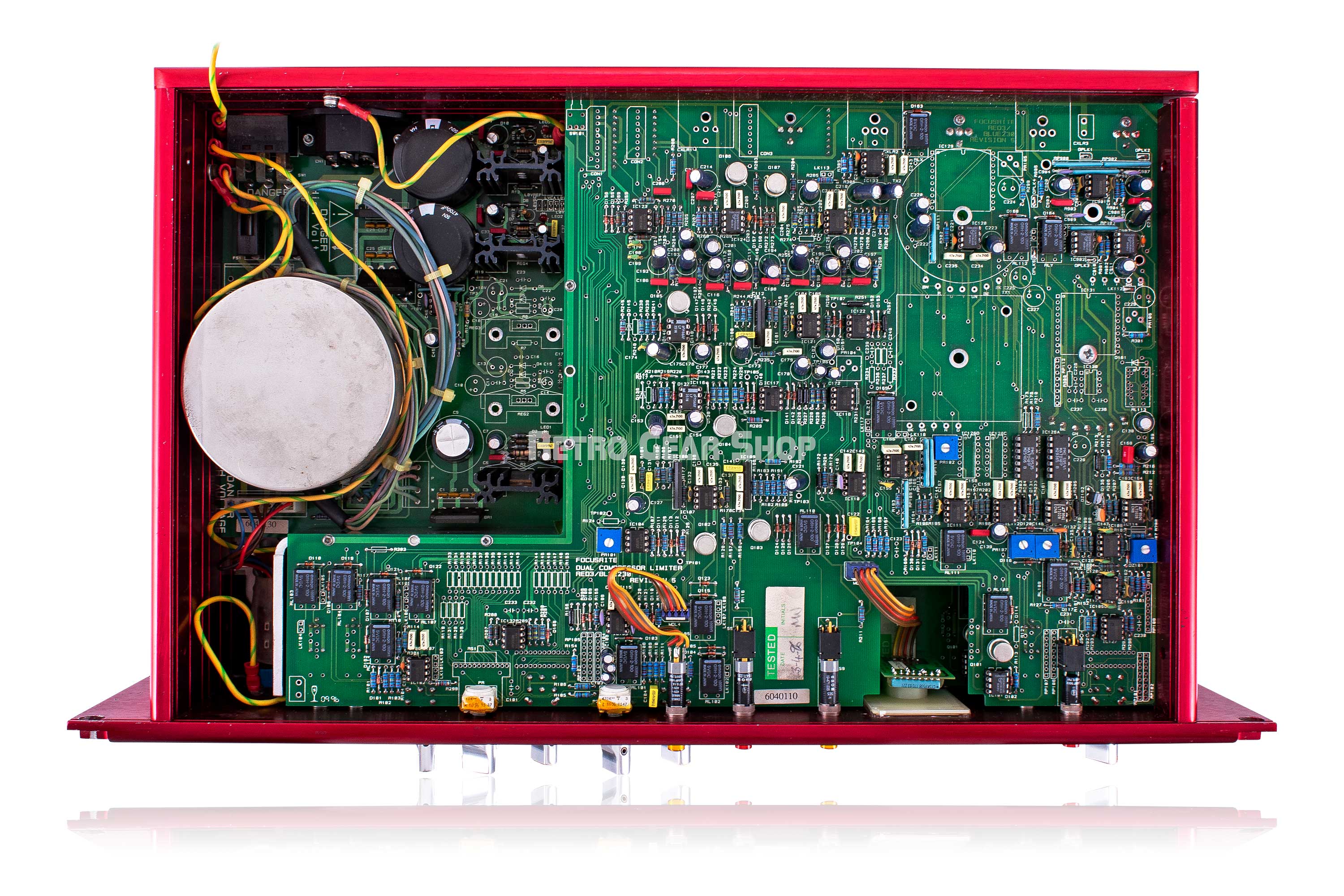
i guess the reason why some older/cheaper gear uses 1000-2200uF PSU filter caps is because of physical size and cost of historically available caps. pic related uses 50V 4700uF that are pretty thicc. if i'm going to shop for capacitors in 2025 i think it's safe to say i can upgrade to at least 4700uF as in
>>2922728 >>2922731.
the voltage rating should be at least 35V to be comfortably within spec of the original designs. polymer electrolytics don't seem easily available at 4700uF but i could maybe use 1000uF polymer in parallel. or for example there is nippon KMH rated for 105C temperature, 100V 4700uF with 35x50mm case size.
https://chemi-con.com/wp-content/uploads/2021/05/KMH-Series.pdf
or for example there is nichicon FW which claims to be suitable for audio use, rated for 85C temperature, 35V 4700uF 18x35.5mm case size
https://www.nichicon.co.jp/english/products/pdf/e-fw.pdf
the nippon KMH seem fine as long as they will physically fit but are there other things to look for and maybe 6800-10000uF would still work
Anonymous
6/9/2025, 2:51:49 AM
No.2922921
[Report]
>>2922930
>>2922916
Only bother upgrading PSU filter caps if PSRR is a bottleneck. If it isn’t a bottleneck, you’re just increasing your turn-on current spike needlessly.
Also don’t buy 85C caps, always get 105C.
Anonymous
6/9/2025, 3:27:31 AM
No.2922930
[Report]
>>2922921
oh yeah i was going to look for info on inrush current. i'm trying to learn all this stuff from scratch. if the quote in
>>2922728 can be trusted it seems helpful to upgrade the secondary caps so that the voltage regulator won't be overloaded with transient current draw? maybe not to 1000uF but like a 100uF audio grade cap or 47uF as in
>>2922414
https://www.diyaudio.com/community/threads/how-to-limit-the-inrush-current-on-a-very-big-linear-psu.375049/
>I have 2 x 3 68000µF
kek
Anonymous
6/9/2025, 3:42:20 PM
No.2923031
[Report]
>You have a voltage regulator. Some are faster than others, but all have a non-zero response time. When load current varies, it won't react instantly. If the load current varies quickly, then you need a capacitor on the output of your regulator to keep the output voltage stable. Some regulators also require specific capacitors for proper operation.
>This capacitor is usually called "bulk cap". Depending on the application, it will be something like 10-100µF (sometimes more) and its purpose is to store enough energy to power the circuit until the regulator reacts to a quick change in current demand.
the bottom right capacitor looks exactly like what shows up on google images for 10uF surface mount ceramic capacitor
>The LT3045 is stable with a minimum 10µF ceramic output capacitor.
might still be comfy to add some more like 47-100uF bipolar electrolytic because in jim williams opinion the drawmer DL241 was current starved and he improved the audio signal to noise ratio by making PSU upgrades including swapping the output capacitor from 4.7uF to 1000uF
Anonymous
6/9/2025, 4:45:59 PM
No.2923040
[Report]
>>2923138
>>2922771
sorry for the late reply.
for starters, the absolute maximum Vgs of that FET is 20 V, so stop putting 20 V across it (i.e. pulling the gate to ground). youll break it.
measuring Vss, Vgs, Vds, and Id is the easiest way to tell what the problem is. and post a less blurry pic of the circuit if you can plz.
Anonymous
6/10/2025, 4:39:37 AM
No.2923138
[Report]
>>2922795
>>2923040
Thank you both. I'll have a bit of time tonight to measure the fet, sorry about the pic, it wasn't meant to convey anything, just a pic of the mess I'm making. I'll learn how to measure everything and get back with a proper picture of the circuit.
Anonymous
6/10/2025, 5:29:30 AM
No.2923142
[Report]
>>2923147
>>2920495 (OP)
I have a keyboard that stopped working properly after a spill. Some of the traces look blackened and burnt so I'm going to try to repair them with a conductive pen.
Can you guys recommend me good conductive pens for this purpose?
Anonymous
6/10/2025, 5:49:03 AM
No.2923147
[Report]
>>2923149
>>2923142
Please show picture of traces.
If it’s those clear plastic flex pcb material, then maybe ok. If it’s a real keyboard (like maybe a mechanical one) it might have a real pcb.
Generally you want silver based conductive pens.
I would argue, though, your keyboard might not be worth fixing,
Anonymous
6/10/2025, 5:57:01 AM
No.2923149
[Report]
>>2923193
>>2923147
don't have a picture but it's a 90s PS/2 Acer keyboard. I may be able to get a similar enough replacement for a decent price, but I would rather fix this one because I like it. And even if I got a new one I would still want to fix this one anyway so as not to create waste.
It uses mechanical switches (manufactured by Alps IIRC, if that matters) atop a clear plastic flexible matrix, not a solid PCB. I'm looking at the Circuit Writer brand of pens at the moment unless someone has an idea for something cheaper or better (or both).
Anonymous
6/10/2025, 12:46:02 PM
No.2923193
[Report]
>>2923285
>>2923149
>a clear plastic flexible matrix
seen quite a few old keyboards where the silver lines have turned black
an eraser brings them back to original color
The pedestal for the M2 screw on my motherboard pulled out of its hole I guess because insufficient solder from the factory, and I think the solder pad for the hole is connected to the ground plane because it just sucks the heat right out of my little 50 watt iron and gets the whole board hot after 10 or 15 minutes of letting it sit in there to try to heat it up but still doesn't get nearly hot enough to actually melt and flow any solder. I was thinking about getting one of those 300 watt Weller soldering guns but they're 80 bucks and I'll honestly probably never use it again. Instead how about one of those $20 zvs drivers you can find on scamazon? They're only 100-120 watts but I figure I might be able to make a smaller coil for it and then heat the pedestal directly which will then heat the solder pad hopefully fast enough to get the solder to flow on to both and lock it in place. Is that likely to work or should I just get the Weller?
Anonymous
6/10/2025, 6:44:19 PM
No.2923240
[Report]
>>2923251
>>2923235
Make a new support with epoxy putty. The edge connector is grounded in the slot, but if you want to ground the support post then use copper tape so it's sandwiched between the PCB and post, running up to the screw hole.
Anonymous
6/10/2025, 7:36:00 PM
No.2923251
[Report]
>>2923264
is there something special about LM324 or is it just that they're cheap so it can otherweise be replaced by TL074 and such? many LM324 aren't even shown in the schematic but they're used for the user interface potentiometers
Anonymous
6/10/2025, 7:37:41 PM
No.2923254
[Report]
>>2923266
Anonymous
6/10/2025, 7:50:49 PM
No.2923261
[Report]
power consumption too i guess because they use TL062 in some places
>TL062 is the low power version of the TL082. TL072 is the low noise version of the TL082. So: the TL062 uses less power, but is more noisy than the TL072.
my understanding is that the potentiometers contribute most of the noise if they aren't new/clean so it's not really worth the effort to replace them but you could replace the LM324 with TL074 if you wanted to, no?
btw i noticed the page numbers so the schematic that's posted online is missing some parts
Anonymous
6/10/2025, 7:55:40 PM
No.2923264
[Report]
>>2923251
Whatever. Use a blowtorch lmao
Anonymous
6/10/2025, 8:23:07 PM
No.2923266
[Report]
>>2923254
or the ones on the daughter board are not for the potentiometers just the indicator LEDs
Anonymous
6/10/2025, 8:35:45 PM
No.2923271
[Report]
https://www.eevblog.com/forum/projects/lm-324-upgrade/
>There is no direct replacement for a LM324 family, since no other opamp family can safely handle voltages on the inputs well over the positive supply. ...
>Plenty do this. Search for "Over the top" or OTT inputs.
this was the source of my confusion. i can barely find any info on "over the top" op-amps and this poster was mistaken because LM324 isn't one of them. so there's not really anything special about LM324 other than its low cost, widespread availability and perhaps low power consumption (i haven't checked the power consumption)
Anonymous
6/10/2025, 9:57:15 PM
No.2923285
[Report]
>>2923193
but does that actually fix the problem? I'll try it in a moment
Anonymous
6/11/2025, 1:20:30 AM
No.2923338
[Report]
>>2923666
>>2923235
Consider getting a tip that allows for better heat transfer, like a broad screwdriver tip. Then ensure it has a layer of leaded solder on it, and also try to float and wick away the existing solder on both pieces to get them all 60/40 too.
By 50W, do you mean regulated or unregulated? Unregulated irons always consume the same power, a 50W iron will get up to its standby temperature (e.g. 450C) and dissipate all 50W of that into the air, so when at a working temperature of 350C you can bet that a good fraction of that power is still being lost to the air. Curie-point, PTC, and temperature-controlled irons do not have this problem. A cheap 60W 936-tipped iron with buttons or a dial on the handle should do the trick.
>>2923252
Ground-sensing, output short capable, stable with small gains, other than that they’re just cheap op-amps. They may have lower DC input offset than TL07Xs, being bipolar instead of JFET op-amps, and they’re being used for DC in your schematic. No real reason to swap them, not like they’re in the audio path. If I were to swap them, it may be with something closer to an OP07, but faster.
Anonymous
6/11/2025, 12:55:46 PM
No.2923421
[Report]
Tomorrow I’ll design a circuit to drive a unipolar (2-phase 5-wire) stepper motor using a pair of 4018 ring-counter chips, maybe a 555 timer too if I can’t get it to self-oscillate.
Any electricians here mind telling me if this is unsafe?
Some backstory:
>Recall on window air-conditioning unit due to water retention/mold concerns
>In order to get your money back the company requires you to take a photo of the unit with the cord cut w/ serial number visible
>Dad thinks he's a genius, decides to get his money back and keep the unit anyway
>Cuts the GFCI cord
>Gets rid of seemingly important copper mesh and insulation around some of the wires since he "doesn't know why they do that"
>Splices the wires together using solder and wire splicers
>Bits of the copper mesh still hanging out
>Whole thing wrapped in electrical tape
I'm not paranoid in thinking this is a bad idea right?
>>2923523
Yes, that's a bad idea. Best way is to open it up and connect the remaining cord that was cut off to its original location. It'll be a bit shorter but it'll be safe, at least. PS, never solder wires like that, especially when high current is involved.
Anonymous
6/12/2025, 1:17:47 AM
No.2923545
[Report]
>>2923565
>>2923523
Your best bet is to run a new power cable at that point, but that will involve opening up the air conditioner, and it probably isn't the best idea either given that your father seems to give zero shits about safety.
Anonymous
6/12/2025, 2:54:08 AM
No.2923565
[Report]
>>2923582
>>2923545
>>2923541
I figured.
Unfortunately he's incredibly stubborn and doesn't believe anything I tell him ever. Not really sure how I'm gonna talk him out of this.
Anonymous
6/12/2025, 3:35:19 AM
No.2923573
[Report]
>>2923580
>>2923523
>copper mesh
odd
if not for that I'd suggest using a splicer like this:
shoulda just photoshopped the cord cut, though you may have missed the copper mesh and maybe they'd have picked up on that
>>2923573
>Photoshop
My dad can hardly work his phone. I had to show him how to upload the picture for the claim.
>Copper mesh
Yeah it was some kind of alternating mesh of copper wire surrounding insulation which covered the ground I think. I wasn't able to get a picture. It's probably something to do with the GFCI? Either way once I saw that I was sure he fucked up
Anonymous
6/12/2025, 4:34:07 AM
No.2923582
[Report]
>>2923565
>Not really sure how I'm gonna talk him out of this.
dont even try
your dad is a REAL man, a national treasure
he repairs cords like a pro and doesnt afraid of anything
you and these other pansies arent worthy of kissing his dick-cheese
Anonymous
6/12/2025, 4:47:18 AM
No.2923587
[Report]
>>2923580
I guess that makes it more likely that cutting the cable while it's live will trip the GFCI. It matters more for something that's partially outside. Interesting.
So long as there's ground continuity through the unit and to the mesh on either side of the splice, the lack of mesh in the splice isn't a terrible thing. And the mesh sticking through, if it's grounded, isn't a hazard either. My only problem with it then is that he used electrical tape instead of heat-shrink or amalgamating tape. Electrical tape just doesn't hold on long-term, especially in any heat.
Anonymous
6/12/2025, 6:10:14 AM
No.2923600
[Report]
>>2923252
LM324/358 can be pulled down to ground. TL072/TL074 have a weird property where they invert their outputs when you pull too close to the Vss rail.
Anonymous
6/12/2025, 9:02:53 AM
No.2923618
[Report]
>>2923629
>>2923580
It's shielding. I assume this is an inverter unit? The motor drivers in those make a lot of electrical noise. Adding grounded shielding to the wire helps keep RF emissions in check.
I guess it could double as a sort of safety if the insulation gets damaged, but I doubt that's its primary function.
Anonymous
6/12/2025, 11:09:00 AM
No.2923629
[Report]
>>2923618
On the mains power cable? Shielding what? The live and neutral wires will radiate fuck-all noise because of their proximity to one another, and any switching noise should be blocked by proper filtration in the unit itself. High-power SMPS like units just use normal unshielded IEC cables. There is a time and place to tackle RF emissions, and the cable is not it. If nothing else because once it leaves your cable and enters the wall via 3-pin plug it's no longer shielded.
Anonymous
6/12/2025, 11:37:00 AM
No.2923634
[Report]
>>2923684
Anonymous
6/12/2025, 12:06:36 PM
No.2923639
[Report]
>needed stripboard with 18 strips of 33 long
>cut out stripboard with 33 strips of 18 long
oof
Anonymous
6/12/2025, 2:33:00 PM
No.2923666
[Report]
>>2923338
I do have a couple of tips including a chisel tip, it's just not enough. There's very little solder on the board like I said that's probably the reason the pedestal came off but while I can eventually melt those tiny bits the heat gets sucked away so fast even a blob of solder that's on my iron at 500c freezes near instantly when touching the board. It's a cheap soldering station and it has a little activity light for the heater so regulated I'm pretty sure. I've even tried to heat it with the iron at 500 and the hot air at 500 blowing on the pedestal sitting in the hole hoping it might remelt the bit of solder there and that I can go from there, but no dice.
Anonymous
6/12/2025, 3:40:25 PM
No.2923684
[Report]
>>2923634
Because the increased resistance can cause the wire to heat up to the point that the solder melts through the insulation, and there's no strain relief. Crimping them or using a Wago would be better but still not great.
>>2923523
Update:
He wanted to drill holes in the back of the AC for drainage and hit the gas line.
Now it's probably leaking Freon everywhere.
Anonymous
6/12/2025, 4:41:18 PM
No.2923697
[Report]
Anonymous
6/12/2025, 5:29:18 PM
No.2923709
[Report]
>>2923749
>>2923690
Is your dad a mexican?
Anonymous
6/12/2025, 7:36:29 PM
No.2923749
[Report]
>>2923755
Anonymous
6/12/2025, 8:38:36 PM
No.2923755
[Report]
>>2923765
>>2923749
>Worse
Impossibru. Mexicans never built a functional civilization or invented anything.
Anonymous
6/12/2025, 9:02:34 PM
No.2923765
[Report]
>>2923784
>>2923755
I've never met a race of humans more stubborn than Italians. When they think they're right, they never back down, even when they are clearly wrong as is the case here.
Anonymous
6/12/2025, 10:42:52 PM
No.2923784
[Report]
>>2923765
I agree. They're definitely knuckleheads for better or worse.
Anonymous
6/13/2025, 12:09:41 AM
No.2923793
[Report]
>>2923800
>>2923690
What's next, refilling it from an air duster can?
Anonymous
6/13/2025, 12:38:55 AM
No.2923800
[Report]
>>2923801
>>2923806
>>2923793
We're tossing them.
Of course he blamed me for jinxing him. All of this because he didn't want to pay the 20 bucks to dump the thing.
Most frugal man I'll ever know. Went so far as to keep half filled dog bags because "they can still fit more poop." Stinking up the whole mudroom for weeks because he didn't feel like spending money on dog bags. Had to talk him out of that too.
Anonymous
6/13/2025, 12:48:17 AM
No.2923801
[Report]
>>2923802
>>2923807
>>2923800
>frugal
Then why does he have AC?
Anonymous
6/13/2025, 12:49:45 AM
No.2923802
[Report]
>>2923801
To make the Italian Ice. Stugots!
Anonymous
6/13/2025, 1:03:27 AM
No.2923806
[Report]
>>2923800
Tell your padre that he can still use the fan and maybe the compressor for an airbrush or a small pump. lmao
>>2923801
He sets it to 78 degrees
Anonymous
6/13/2025, 1:19:24 AM
No.2923811
[Report]
>>2923807
Too hot for curing gabagool.
Anonymous
6/13/2025, 2:16:28 AM
No.2923819
[Report]
>>2923826
>>2923807
You use °F in Italy?
Anonymous
6/13/2025, 2:42:47 AM
No.2923826
[Report]
>>2923819
Whatsamatta, fanook?
Hello ohm I have a question in regards to project I am working on, I am wanting to do a battery mod for my digital calipers, and gives me an opportunity to use a 3.7v lipo with 75mah, a while back I bought these usb type c modules that has 4057 (not 4056) IC
the usb type c module is
>lx-lbes
obviously I want to lower the charge current since these come as 1A charge current.
I cant post the damn datasheet link bc 4chan system think its spam.
Assuming this datasheet is for this chip, and with pic related, would I assume the far right column is resistor values? and with it "K" do I assume 24,000 resistor value would be ideal for the battery I want to use?
Maybe its obvious but for the sake of asking and looking like and idiot, I rather ask just to be sure.
>>2923940
Pretty easy to double-check this one. Yeah it means kΩ.
>>2923940
For your battery you want 24kΩ or higher between the prog pin and ground for 1C. If you want the battery to live longer, use 50kΩ. It's the difference between 500 charge/discharge cycles vs. 2000 cycles in its lifetime.
Anonymous
6/13/2025, 10:04:26 PM
No.2923946
[Report]
>>2923983
>>2923944
>components101 watermark
I searched "TP4057" and nothing shows up. If you searched what keyword did you use?
>>2923945
oh yeah that makes sense, I forgot I was reading about charge current you want it to relatively be half of the mah capacity. I even forgot to ask if I should go for 50k to prolong its life, and I have 51k resistor so that works out for me.
Anonymous
6/13/2025, 10:13:49 PM
No.2923947
[Report]
>>2923948
>>2923983
>>2923944
Actually anon I just noticed that is a 6 pin schematic, the one I have is 8 pin, and sorry the datsheet I referenced is "ME4057" the pins seems to be the same
Anonymous
6/13/2025, 10:29:11 PM
No.2923948
[Report]
>>2923957
>>2924264
Anonymous
6/13/2025, 11:29:53 PM
No.2923957
[Report]
>>2923948
>tfw thats the datasheet I wanted to link but 4chan system thought my post was spam until I removed that link
I swear I'm not that dumb.. I am.. but not alot.
i have a 65W lenovo laptop charger that i want to use as a power source for a battery charger i'm designing. if i want to get the full 65W output, can i just use it as a 'dumb' device or do i need to go through the whole power delivery negotiation ordeal?
hey all, im working on a tamagotchi game x weed battery project with a rpi pico. Not really asking much about the controller itself but basically I want to use the 3.3v output that uses a voltage regulator to have "temperature settings".
I'm a little unsure on how the heating of the coil inside would work, would I need to be supplying a certain amount of voltage? or is it more current related? I tested once using 3.8v output with resistors and 5v output but my friend tested it and apparently he couldn't get smoke to come out
Anonymous
6/14/2025, 1:53:42 AM
No.2923974
[Report]
>>2923975
>>2923972
Some power bricks incorporate a chip with a flag set to identify its output capabilities to the host device. You can remove/bypass it or modify the flag (with a replacement IC), but 65W is standard and it should just give you the full output without trickery. It won't work if you try to power a device that requires more than 65W, obviously.
>>2923973
You want to control boosted power to the coil with pulse-width modulation?
Anonymous
6/14/2025, 2:01:41 AM
No.2923975
[Report]
>>2923974
Uhhhh pwm? i didnt have pwm in mind, can you clarify why you asked that? maybe im missing something but i thought i can figure out my own separate circuit that changes voltage output with a button
Anonymous
6/14/2025, 3:15:33 AM
No.2923983
[Report]
>>2924264
>>2923946
I searched “tp4057 schematic” on ddg images.
>>2923947
You could see if the datasheet has an equation instead. Or look for an appnote or other existing circuit. Or measure the current going into an 18650.
>>2923972
Is it USB C? A simple PD trigger board set to 20V will work for that. If not, generally power bricks output a constant voltage without worrying about their communication pin, but I may be wrong. Maybe some guys on the eevblog forum have an old post up about using Lenovo power bricks.
You might find it more convenient to talk USB PD PPS to it to get the voltage or current you need without any additional power electronics, if it’s supported, but you’d need a microcontroller for that I believe. WCH have a few that do that IIRC, otherwise you can look at what chips the Pinecil and TS101 use, they can likely do it. The same goes for if you want to be able to use any arbitrary power brick, and have the battery charger respect the power output of the power brick without drawing too much.
>>2923973
Heating coils are resistors, hence V=I*R and P=V*I apply. As the other anon said, PWM. Because it’s a high-power peripheral, you’ll want to use the unregulated battery voltage directly as to not overload the regulator, but use a transistor controlled by the Pi Pico to switch it on and off. Maybe PWM, maybe with feedback, maybe both.
Anonymous
6/14/2025, 3:20:14 AM
No.2923984
[Report]
>>2923973
To clarify with V=I*R and P=V*I, if you already know your voltage (e.g. 3.7V from a single lithium battery) then you need to select your heater based on the amount of power you need it to dissipate. Maybe 10W is enough, so we can rearrange the top two formulae to get P=(V^2)/R, or R=(V^2)/P, so R=(3.7^2)/10 = 1.37Ω. Though note that battery voltages decrease as the battery empties, so you may want to add some extra margin. Or even calculate it for minimum voltage (e.g. 3.2V) and do software compensation by turning it on less at higher voltages.
Need some help diagnosing some shit bros.
I picked up a Nord Piano 3 yesterday. Apparently it was flooded at some point, owner took it apart and dried it all out then put it back together and ti sort of worked at which point he set it aside for some indeterminate time until deciding to get rid of it yesterday.
I turned it on, it sort of works. Plugged it into my computer, was recognized, nord software updated teh OS and I did a factory reset. Sent MIDI fine, except the lowest 16 keys aren't working. Also plugged headphones in and it sort of worked. Made sounds and some controls worked, but others didn't. Notably the screen seems dead, the knobs to switch instruments do nothing (but maybe I'm not doing it right since the screen is dead dunno), some of the effects section seem dead, wouldn't come on, others weren't quite functioning right, like various options that have an led when you select them, but the leds remained on.
So anyway, the question is, what exactly am I looking for when I crack it open? The keys I'm hoping it's just a bad connection at the plug or something simple, but the semi-functioning electronics.... Not sure. In previous stuff I messed with shit just worked or didn't no weird in between. Also maybe this would be better in the microcontroller general?
pic related for reference, haven't cracked it open yet.
What kind of tools do I need for testing? I've got a cheap multimeter and that's about it lol.
Anonymous
6/14/2025, 4:19:54 PM
No.2924072
[Report]
>>2924090
>>2924060
Given this some more thought, and considering that MIDI output (over USB haven't tried the MIDI jack yet) and sounds work, and was able to connect and update without issue, I'm guessing the problem (other than the non-functioning keys) is likely solely in the board for the front panel controls. Dunno if that's good or bad, but it seems like the actual logic chips are probably fine.
So I've got the dead oled screen and some non-functioning pots and buttons, plus many indicator leds that are erroneously on. What sort of issue would cause that?
Anonymous
6/14/2025, 5:16:20 PM
No.2924090
[Report]
>>2924110
>>2924060
>>2924072
Put your meter in continuity mode and test all the buttons with the power off. Then test the resistance of the pots as you turn them back and forth. Inspect all the solder joints with magnification. After that, power on and probe for voltage at all ICs, regulators, and cables/connectors.
Opened the piano up, found the keyboard problem, these shitty connectors. The small one is chipped it looks like and the cable is loose in it. But wiggling it around more of the low keys worked, though not all.
Also got the panel/controls board off, looks clean on the top, but back some white residue and some solder joints look a bit shitty.
Anonymous
6/14/2025, 6:22:11 PM
No.2924109
[Report]
Anonymous
6/14/2025, 6:23:20 PM
No.2924110
[Report]
>>2924090
I'll give it a shot and see what it says.
Anonymous
6/14/2025, 6:35:00 PM
No.2924112
[Report]
>>2924107
Use IPA or contact cleaner on the ribbon cables and connector. Use a toothbrush to scrub the connector, and cut a small piece of thin plastic to wedge behind the ribbon cable so it's making better contact. Worst case you can solder a wire harness to the connector's contacts, or replace the connectors and ribbon cables.
Anonymous
6/15/2025, 4:28:36 AM
No.2924201
[Report]
https://gearspace.com/board/attachments/geekzone/394197d1397243235-drawmer-dl241-schematic-dl231-drawmer_dl241.pdf
it was a bit of a pain just trying to verify feed forward vs feedback topology but i think i figured it out. it's feedback? the output of VCA CIRCUIT feeds into LIMOUT and LIMOUT goes to the output stage. but before LIMOUT comes PEAK CIRCUIT which feeds into LIM_CV. LIM_CV then leads to VCACTRL on the previous page. and VCACTRL of course provides the feedback to the DBX 2151 VCA.
funnily enough, VCA compressors with feedback topology are considered a bit exotic. i think drawmer 1978 is also feedback but people don't outright say it so you have to decipher the block diagram. so i think drawmer 1978 could be a viable poorfag alternative to the API 2500 compressor. and there is less "redundancy" to worry about if you have for example feed forward VCA compressors with hard knee, with soft knee, then this drawmer with soft knee but it's feedback so you can justify keeping all these compressors in your rack because they all have a different character from each other.
Anonymous
6/15/2025, 5:39:32 AM
No.2924223
[Report]
i think it's the missing pages in the schematic that messed me up. the input branches to the VCA and to INBUFF which would be how feed forward is done. presumably INBUFF leads to DETIN which leads to the SSM2120 level detector. then EXP_OUT leads to EXP_CV and COMP_OUT leads to COMP_CV. EXP_CV, COMP_CV, LIM_CV all lead to VCACTRL but maybe it's only the limiter that's feedback and the compressor is feed forward.
Anonymous
6/15/2025, 1:15:54 PM
No.2924264
[Report]
>>2924337
>>2923944
>>2923945
>>2923948
>>2923983
Some of these replies I am doing are probably samefriend but I figured I'll include all replies.
I never soldered 0603 sized resistor and while its not on there straight, its good enough, it was a small learning experience made some short sighted mistakes, next time I'll just pre solder one pad, I pre soldered both pads and soldered both ends and didn't have it fully sitting, and have trouble wicking away the solder on one end so I just rolled with it.
As I am making this comment I just remembered I bought a small hotplate so maybe
>https://www.aliexpress.us/item/3256806193753913.html
this probably gives me a chance to try it on this usb to fix the botched solder job.
Anonymous
6/15/2025, 4:55:17 PM
No.2924291
[Report]
>>2924293
>>2924287
Why nand gates?
If you have nand gates, why not build it on a breadboard instead of simulating it?
Anonymous
6/15/2025, 5:02:14 PM
No.2924293
[Report]
>>2924291
i have some nand gates on hand. if i'm making a mistake in a simulation why would i waste my time breadboarding it? i got the 3-input OR working. the issue is i'm doing something wrong (or not understanding something) when i want to latch it high.
Anonymous
6/15/2025, 6:56:18 PM
No.2924307
[Report]
>>2924339
Anonymous
6/15/2025, 10:23:26 PM
No.2924333
[Report]
>>2924353
>Remember that the AC Amps of the transformer is typically twice the DC load current. Your 1.5A DC load needs a 3A AC transformer.
so let's say an existing design has a split-bobbin transformer with 18V 0.7A output, and the external power rating is only 9-15W. then a 15V 0.5A DC voltage regulator should be fine.
though what about some others that have 30-36W power consumption printed on the rear panel and which might have toroidal transformers of unknown current capacity instead of split-bobbin. some might still use a single set of 0.5A voltage regulators (one for positive 15V and one for negative 15V). some might use 1A voltage regulators but if i want to put in high precision 0.5A regulators instead, how do i calculate the margin of error. the 30-36W rating on rack gear ought to be "at the wall" power consumption before the efficiency loss of the transformer.
Anonymous
6/15/2025, 10:36:00 PM
No.2924336
[Report]
>>2924353
the 0.5A regulators can be pushed to 0.7A
Anonymous
6/15/2025, 10:38:21 PM
No.2924337
[Report]
>>2924916
>>2924264
Cool. Though from here it doesn’t look like that right-most solder-joint is making any contact.
Anonymous
6/15/2025, 10:48:49 PM
No.2924339
[Report]
I've got this meme EEG headband (muse S), which I actually do like, but the electrodes on the soft strap are degrading. They have to make electrical contact with skin, but the silver ink is flaking off the backing fabric. According to the manufacturer it's "Conductive silver ink on flexible fabric adhesive".
Ideas on how to repair this? I could get some more silver conductive paint of course, but given all the patch needs to do is be 1) conductive and 2) somewhat flexible, I'm wondering what else I could try. charcoal/graphite comes to mind. or aluminum foil, though I don't know how well that'd conduct to skin.
Anonymous
6/15/2025, 11:50:15 PM
No.2924353
[Report]
>>2924333
>>2924336
google gemini said this (assuming 60% efficiency, 35W max power, so 21W DC power, 10.5W per 15V rail assuming even split between rails)
>Current Rating (0.5A): While 0.5A might cover the average current draw for some parts of the audio circuit, it seems borderline or potentially insufficient if the audio device is actually consuming near its maximum 35W, and a significant portion of that power is handled by the regulated 15V rails. The calculations show that each regulator would need to supply about 0.7A if the power were evenly split across the rails.
so it's a bit sus but maybe if the stock regulators are actually 0.5A then it might work (though the datasheets say "in excess of" 500mA with good heatsinks) and maybe i can measure the actual power draw at the wall or even probe the internal voltage stability (i won't use all features at once in practice anyway, some parts of the circuits will be bypassed with electrical switches)
Anonymous
6/15/2025, 11:57:38 PM
No.2924356
[Report]
Anonymous
6/16/2025, 12:00:09 AM
No.2924357
[Report]
>>2924344
I’d try casting a conductive (thermoset) elastomer into the desired shape, probably graphite-filled PU or silicone.
Anonymous
6/16/2025, 12:37:49 AM
No.2924361
[Report]
>>2924344
whatever that thing is even *claiming* to do, doesnt require conducting to your skin.
Anonymous
6/16/2025, 3:12:36 AM
No.2924374
[Report]
>>2924375
>>2924344
Well, I tried making some conductive paint out of some activated carbon powder I happened to have, plus some elmer's glue. It didn't work unfortunately; at least the bundled software still reports a bad signal from those electrodes. Could also be the lead from the electrode to the rest of the hardware. Once I figure out where my multimeter went I'll measure the actual resistance.
>>2924374
The glue encapsulated/insulated to graphite. You can buy adhesive electrode pads for TENS units and such. Giving yourself some electroshock therapy, Anon? I recommend sunlight and fresh air instead. Drink plenty of water too.
Anonymous
6/16/2025, 3:23:15 AM
No.2924376
[Report]
>>2924375
Hmm, how do other conductive graphite paints suspend the carbon particles then? FWIW I also found a set of metallic sharpies, which mayybe are also conductive, but my real problem is not having a multimeter to test any of this. Guess I'll go to the harbor freight tomorrow and get another cheap one.
The headband is an actual EEG and you can read the raw data out of the 5 electrodes over python, which I've messed around with some. It's nowhere fine-grained enough for like mouse control or anything, but I've thought about hooking it up to MIDI CCs to do dumb music shit with. I honestly like the on-label use for it too, which is measuring how "calm" you are during medition. It's again not super accurate but it's neat to have an input signal you can control purely with your mind.
Anonymous
6/16/2025, 3:35:01 AM
No.2924379
[Report]
>>2924378
>how do other conductive graphite paints suspend the carbon particles
I don't know, but it probably involves a conductive adhesive. Have you tried experimenting with pancake coils? You might be able to get more granular feedback that way, but I don't know anything about biomedical devices. Just throwing stuff out there.
Anonymous
6/16/2025, 3:43:50 AM
No.2924381
[Report]
>>2924378
Metallic sharpies use mica powder and maybe a small amount of aluminium. To get something conductive you need a shit-ton of graphite, make it really dense and gloopy. It probably also matters what affinity the glue has for covering the surface of the graphite.
I did it once by mixing ground-up charcoal with house paint, it was decently conductive. I also made the charcoal from sticks from my garden chucked in an empty tuna can atop a camping stove in my driveway. Fun times.
Anonymous
6/16/2025, 11:42:32 AM
No.2924440
[Report]
>>2924444
I want to make a small custom transformer for a VFD (the display, not the motor driver).
What's the smallest total amount of windings I can get away with?
Like let's say I need a 1:10 ratio, what changes if I use 2:20 windings compared to 10:100 windings?
Anonymous
6/16/2025, 12:59:53 PM
No.2924444
[Report]
>>2924447
>>2924440
Why a transformer? An isolated driver for the cathode heater? Or for the total DC bias? You could use a charge pump instead for either of those, VFDs don’t eat much power after all.
Transformer size and winding count is a function of core material and of frequency, in addition to the current and voltage output you desire. You might be able to handle very few turns using a low frequency and a fancy core material like metglas (Marco Reps made such a converter for a low-leakage PSU), or by just using a very high frequency and a conventional ferrite core.
The magnetic flux stored in the core is a function of the amps multiplied by turns (amp-turns), and different core materials have different maximum capacities for this flux. Energy stored in the transformer’s magnetic field is a function of this magnetic flux, so moving more cycles of the same amount of flux through the core means higher power.
What converter topology are you intending on using anyhow? FYI flyback converters need a special kind of magnetic core, one with an air gap. Personally I’d suggest a push-pull converter, the TL494 makes this pretty easy. You can use it to drive MOSFETs with some extra circuitry, but in this case a pair of external BJTs would work fine, if that. You can simulate such circuits in LTSpice or similar to some extent, but I greatly recommend building some rudimentary circuits on a breadboard to see how they behave. A scope is recommended to see the switching waveform.
Anonymous
6/16/2025, 1:22:01 PM
No.2924447
[Report]
>>2924471
>>2924444
I saw Noritake recommending a center-tap transformer for the drive:
https://www.noritake-elec.com/technology/general-technical-information/vfd-operation
>Transformer size and winding count is a function of core material and of frequency, in addition to the current and voltage output you desire.
So what happens if the winding count is too low? Excessive core losses?
If I'm experimenting with it, what tells me that I need to increase the winding count? Does it just heat up?
Anonymous
6/16/2025, 1:27:34 PM
No.2924450
[Report]
>>2924468
/ham/ crossover here
was just looking at a soft start board but I am unable to fit it in the chassis of the amplifier
was thinking why their isn't current sensing soft start boards available. Then it would just be inline with the power cord and once it starts seeing actual current draw through the NTC thermistors it can run the timer to kick on the relay for full power.
The current board I have simply starts timing from the instant it receives power since it assumes it would be switched on from the amplifier itself.
>>2924450
Move the whole DC output stage out of the amplifier and into a separate box.
Probably the way it should be.
Anonymous
6/16/2025, 4:44:51 PM
No.2924471
[Report]
>>2924447
> winding count is too low? Excessive core losses?
Lower resistance means it sucks more power.
More power means higher magnetic flux.
If it exceeds the amount of flux the core can “store” then yeah… lower efficiency.
> where does the excess energy from the low efficiency go?
Almost always goes to heat. In general.
Even if your transformer is buzzing, that buzz and the sound it makes all gets turned into heat eventually.
In the case of a transformer with gaps in the core, it acts like a choke. Which is to say the magnetic flux is not completely transferred to the other windings, but stays around the primary and generates reverse “back emf” which appears to raise the resistance of the winding so it draws less power. This depends on frequency, too.
Anonymous
6/16/2025, 5:02:36 PM
No.2924473
[Report]
>>2924475
So, I'm in need to have a high power FM Transmitter. What's the cheapest and fastest way to get there. my spy bug style fm transmitter barely has coverage of 500m
Anonymous
6/16/2025, 5:12:14 PM
No.2924475
[Report]
>>2924486
>>2924473
Is there something going on in /ham/ right now?
Instead of adapting an RF amplifier to the FM transmitter, the easiest thing to do is likely use a repeater.
You could easily use a couple of radios linked together (e.g by audio, possibly with vox) to re-transmit it, perhaps to another frequency. If you use, say, gmrs, that’s going to be more plausibly legal than amplifying the transmitter output.
Anonymous
6/16/2025, 6:19:50 PM
No.2924486
[Report]
>>2924507
>>2924475
Oh I want to be a whistle blower with a level of anonymity. I am planning to set up a transmitter truth near religious places and expect them to go ape shit
Anonymous
6/16/2025, 8:23:54 PM
No.2924507
[Report]
>>2924589
>>2924486
>anonymity
lmao
>religious places
mosques? temples?
>>2924468
that's a possibility
It's a Heathkit SB-1000 linear
the transformer has been replaced with one that barely fits so it's all a bit of a mess, otherwise a well put together kit
works but causes hell on my house wiring and the magnetic flux when powered on actually sucks the side panel of the case towards it during power on
would have to get some nice wire to send the 700vac up to the filter and rectifier board though if the transformer was remotely located
Anonymous
6/16/2025, 8:25:51 PM
No.2924509
[Report]
>>2924508
with this upgraded transformer the unloaded voltage after rectification is more like 3500v fyi
Anonymous
6/16/2025, 8:40:05 PM
No.2924510
[Report]
>>2924508
pic related
it had a resistor style soft start when I bought it but it got fried due to a bad tube causing overcurrent issues
>>2924508
> the magnetic flux when powered
That’s exactly the reason why it should be in a separate box to begin with.
With some big linear audio amps, it helps prevent the 50/60Hz hum emitted from the transformer from getting picked up by the amplifier.
So, we put it in a separate, ferromagnetic box, snd run a shielded power cable to the amp.
Factory units have the psu in one box for other reasons besides quality.
But you don’t need to be bound by that.
Anonymous
6/17/2025, 1:52:46 AM
No.2924561
[Report]
>>2924573
>>2924549
wouldn't there be unintended consequences to extending the transformer wires? Especially for the filament lines?
Anonymous
6/17/2025, 2:45:28 AM
No.2924564
[Report]
>>2924468
>>2924549
On this topic, what sort of connector should be used for multi-winding AC power supplies? Something like a DIN or microphone plug? Or maybe a D-sub 3W3-8W8? Is there anything as standardised as DC power connectors (5525, anderson, etc.)? I know there are some NEMA or IEEE LV AC plugs, but they have three phases at best and are intended to be all the same voltage.
>>2924561
> filament lines
Are those the 3KV lines? Special wire, and precautions, obviously. It’s nothing that didn’t used to happen in a CRT enclosure though.
> as standardised as DC power connectors
For the last couple of years I’ve been using AMASS XT60s for everything. They make 3-pin and what not too.
Also XT30 and XT90 and family (30 Amp and 90 amp)
They also make crazy connectors with data, in case you want to backfeed some digital control signals from the front-end to the soft-start.
Picrel is for that guy that posted those expensive-ass D-Sub connector pr0n with power pins.
Anonymous
6/17/2025, 5:02:27 AM
No.2924574
[Report]
>>2924573
no filament voltage is 5.2vac at about 14-15 amps
for the tube filament heater
Anonymous
6/17/2025, 5:05:25 AM
No.2924575
[Report]
>>2924573
Here’s the D-Sub 8W8 connector (also standard) if you have deep pockets, and want to impress chicks that you convince to come back to your lab.
Anonymous
6/17/2025, 5:07:56 AM
No.2924577
[Report]
military connecter/cannon plug would be the chad choice
Anonymous
6/17/2025, 5:30:17 AM
No.2924580
[Report]
>>2924583
dunno how relevant this is gonna be for you guys, but anyway
>>2924578
Anonymous
6/17/2025, 5:36:58 AM
No.2924583
[Report]
Anonymous
6/17/2025, 6:08:04 AM
No.2924589
[Report]
>>2924507
>worse
Gurudwara. Those fuckers are armed 24x7
Anonymous
6/18/2025, 7:40:32 AM
No.2924856
[Report]
>>2924865
How can I buy a DC constant current rated for like up to 160v? I have 128v nominal and I need to limit it to 12A so that's a sizeable amount of watts. I haven't found anything that operates in this voltage range.
Maybe I have to build one or modify an existing one?
Anonymous
6/18/2025, 7:44:45 AM
No.2924857
[Report]
>>2924860
>Bear also in mind, the larger the coupling/output capacitor you install, the longer the time constant for charging it to '0V'. Larger caps will make larger thumps or pops and cause more woofer movement in a DC coupled power amp.
i have yet to see a thorough explanation of how this works
how about if my outboard gear and my audio interface is all connected to a patch bay with a shared ground and i don't listen to any of it while it is powered on and the capacitors are being charged
after the capacitors are charged, i can re-route things without getting pops?
if i modify my audio interface so that the interface and the outboard gear still have output capacitors but i remove the input capacitors from the audio interface so the inputs are DC coupled. then if the outboard gear has a hard bypass switch so instead of the signal passing through the output capacitors of the outboard gear it goes directly from the interface output to the interface input, can i toggle the bypass switch back and forth without getting pops?
>>2924857
> i have yet to see a thorough explanation of how this works
The capacitor and your load impedance (a speaker if we’re talking about an amplifier) make a high-pass RC filter. That RC filter has a time constant.
>after the capacitors are charged, i can re-route things without getting pops?
This would work, yes. You’d have a dummy resistance to charge up the caps with, then like a soft-start circuit you’d have a time delay or voltage threshold that switches a relay to the main speakers.
I’d be wary of having no input caps on your equipment, if any circuitry in them relies on 0V DC offset (some implementations of peak-detector circuits like compressors, for example) it could disturb that.
Anonymous
6/18/2025, 9:35:10 AM
No.2924865
[Report]
>>2924930
>>2924856
> DC
> constant current
Get two or three and put them in series.
Some are designed to work in that mode with multiple outputs and brass shunts that comw with the unit,
Anonymous
6/18/2025, 9:37:35 AM
No.2924866
[Report]
>>2924869
>>2924860
> RC filter
Isn’t that more of an LC filter?
LC > RC except it’s hard to wind coils
Anonymous
6/18/2025, 10:09:27 AM
No.2924869
[Report]
>>2924866
Yes and no, when you’re at the 10Hz and below territory the resistance of a speaker will dominate its inductance.
Anonymous
6/18/2025, 11:51:23 AM
No.2924879
[Report]
>>2925007
I made a grass trimmer and the 35A fuse on the battery melted (literally)
I switched to a different battery without fuse and then the cables that go from the ESC to the motor almost melted as well
if I don't want to limit the throttle, is there anything I can do other than using beefier cables?
my battery (36V) should output 40A without too much issues, the ESC is rated for 60A and the motor is rated for up to 65A at 36V
Anonymous
6/18/2025, 12:14:10 PM
No.2924882
[Report]
https://gearspace.com/board/new-product-alert-2-older-threads/1445414-motu-ships-redesigned-16a-audio-interface-9.html#post17474579
they're able to hear that this interface sounds like shit
it has better SINAD than the lynx hylo but... the phase is fucked up
pajeet tier engineers just parrot the dogma that phase doesn't matter in audio but phase is the main thing that gets messed up in DAC oversampling filters and why professionals pay thousands for good converters
Anonymous
6/18/2025, 2:43:58 PM
No.2924916
[Report]
>>2924337
Agreed, tried to wick solder on the left so it can move freely, but 1. when I did heat the solder on the left the right side had enough solder to keep it in place, and 2. to verify this I ran continuity from the right side to pin 2, showed continuity, and as a extra precaution I did continuity from the left side of the resistor, and it showed continuity it didnt beep it just had numbers jump around on my multimeter which idk the reason but experience and history tells me that its not a direct connection but it connects.
>>2924865
>Get two or three and put them in series.
Is this how to successfully overvolt a mosfet? Or does the gate to drain voltage not spike enough to kill it during operation? It sounds extremely sus.
I was thinking about taking an existing one and modify it with bigger mosfet but
Anonymous
6/18/2025, 5:41:52 PM
No.2924949
[Report]
>>2925007
Will this 100-120w temperature-controlled soldering iron powerful enough for general usage?
Anonymous
6/18/2025, 5:59:50 PM
No.2924951
[Report]
>>2924930
You’re supposed to protect G with:
1. A zener diode.
2. A big current limiting resistor.
>>2924879
What size wires are you using?
>>2924930
No, you’re better off buying higher-voltage lower-current MOSFETs and putting them in parallel. But isolated PSUs are pretty safe to put in series, because they don’t need to be synchronously tied together, and their gate driving circuitry for any internal MOSFETs is floating with respect to the other supplies.
>>2924949
Yes, but the tip-to-grip distance is pretty bad compared to a lot of alternatives. Even a shitty Yihua 938D-III looks better for that, let alone anything with cartridge tips. The gold standard for tip-to-grip distance is either the colletless T12 pencils, or most JBC cartridge pencils (leg. t245). Though most stand-alone regulated irons with these tips will run on a DC jack or USB C, and not have the best tip-to-grip distance, as compared to the two-part soldering stations. Cartridge tips also give you more responsiveness; faster temperature changes and power ramp-ups when encountering a thermal load.
Anonymous
6/19/2025, 8:07:53 AM
No.2925116
[Report]
>>2925121
>>2925007
>What size wires are you using?
16AWG from ESC to motor, ~120cm/45inch long
Anonymous
6/19/2025, 8:26:42 AM
No.2925121
[Report]
>>2925131
>>2925116
Do you know how many amps 16awg can handle? It's less than 25A by any reasonable metric. I'd want at least 12awg for pulsed operation, closer to 8awg for minute-long operation at that current.
>>2925007
>Yes, but the tip-to-grip distance is pretty bad compared to a lot of alternatives.
>https://www.youtube.com/watch?v=KV1miDUIJI4
From the demo vid, I kinda like them FAT but also short, and $55 for a Japanese-made tool is just too good, even though I have to buy them from Aliexpress
And I think this thing is heat-up pretty damn fast too, not on the stationary type level but still damn fast and also grounded
Anonymous
6/19/2025, 10:02:14 AM
No.2925131
[Report]
>>2925134
>>2925121
thought so, but I used AWG16 because that's what both ESC and motor came with
the connectors between them are MT60 which are rated for 30A too... I'll try to upgrade to AWG14 since a bigger one wouldn't fit in the connector anyway, and I'll have to limit the max power from the controller
thank you for replying Anon
Anonymous
6/19/2025, 10:57:16 AM
No.2925134
[Report]
>>2925126
>$55
That's pretty good. Especially for that kind of power rating from a name-brand.
>>2925131
I'm guessing the motor is intended to be run at a much higher speed (e.g. a propeller), and hence draw less current in steady-state. You can fit 12AWG in XT60-like connectors, but if those are XT30-sized instead you'll probably be stuck in the 16awg ballpark. Upgrading the connectors and wires for the entire unit wouldn't be easy, considering you'd need to do some serious soldering on the big power-planes inside the ESC, and figure out how to solder wires inside the motor. Only thing to do is set some sort of average current limit, that allows for spikes but not continuous operation above 20-30A or so.
Anonymous
6/19/2025, 12:31:42 PM
No.2925140
[Report]
>>2925142
>>2925126
If you REALLY like that form-factor in your hand then just get it anon, that shit will outperform all of the usb-c powered ones and most likely will outlive them as well, just beware there are tons of Hakko and Goot cheap clones everywhere
Anonymous
6/19/2025, 12:45:12 PM
No.2925142
[Report]
>>2925140
>that shit will outperform all of the usb-c powered ones
Well arguably the TS101 and Pinecil with 28V PPS can go higher using IronOS, but it's not recommended. The Sequre S99 and the Yihua 928D-IV (yes the IV is a USB iron) use T245 tips so can probably handle higher powers than the T12, TS, ST, or SH72 tips can. Seems like the S99 can go up to 150W if you get the right power brick for it, and buy a proper 2.5R tip instead of the 5.5R one it comes with.
If I already had T245 tips and the S99 had a barrel jack too, it would be a nice addition to my toolbox. I got the Si012 Pro instead because I already have a bunch of T12 tips.
Need help. How do I create something like picrel? That is: turning connection of a disk to the motherboard on/off. Can this be achieved "mechanically", without programming microcontrollers etc.?
Anonymous
6/19/2025, 1:26:17 PM
No.2925147
[Report]
>>2925158
>>2925144
L M A O
I'm assuming he's switching the power to each drive, and the BIOS is booting from whichever drive is detected. That's retarded.
>>2925144
>Can this be achieved "mechanically"
yeah, pretty easy if you're either knowledgeable or brave
- easiest is to leave the computer side panel off so you can plug or unplug wires to the drive of choice - you can pull either the power cable (multi-color one in pic) or the data cable (red) or both
- second easiest is to use an external drive for one of the OS'es. set the BIOS to boot from external drive first. so, if you have the external drive plugged in at power-up, one OS is chosen, otherwise the other is chosen
- third easiest is to use a DPDT switch to send power to only one of the 2 drives. you'd switch the red and yellow wires in the power cables to both drives
Anonymous
6/19/2025, 2:04:47 PM
No.2925158
[Report]
>>2925176
>>2925147
> I'm assuming he's switching the power to each drive, and the BIOS is booting from whichever drive is detected.
Yep, that's the plan.
> That's retarded.
It's just like.. your opinion man.
>>2925150
Thanks, What I was looking for is the third option.
Anonymous
6/19/2025, 3:29:06 PM
No.2925176
[Report]
>>2925191
>>2925150
that reminds me one old pc was setup that if one special diskette was in it it booted from the second drive instead of the first
>>2925158
just do that with a pendrive, make boot from the pendrive and put in the pendrive to boot the second ssd instead of the first
Anonymous
6/19/2025, 4:37:39 PM
No.2925191
[Report]
>>2925176
>special diskette
AUTOEXEC.BAT
CONFIG.SYS
The good old days.
Anonymous
6/19/2025, 4:57:50 PM
No.2925196
[Report]
>>2925236
>>2925144
>>2925150
I think technically you need to connect some wires before others for hot plugging to work.
That's why the contacts on the SATA connector have different lengths.
Anonymous
6/19/2025, 7:15:01 PM
No.2925225
[Report]
>>2925227
>>2925150
Do drives still have the C: or D: jumper?
(Or primary/secondary)
That would be easiest in my opinion
Anonymous
6/19/2025, 7:20:55 PM
No.2925227
[Report]
>>2925230
>>2925225
>C: or D: jumper
That was superseded by the SATA interface in 2003.
Anonymous
6/19/2025, 7:29:32 PM
No.2925230
[Report]
>>2925237
>>2925227
I think it was obsolete even in later PATA standards.
Anonymous
6/19/2025, 7:34:52 PM
No.2925236
[Report]
>>2925196
For sata it just ground that needs to be connected first, that's why the fingers are longer.
It just forces the ground potential to match so there isn't any potential high voltage differentials on the power/data pins.
For 2.5in drives you merely need to switch 5v, 3.5in drives need 5v and 12v switched.
Anonymous
6/19/2025, 7:38:58 PM
No.2925237
[Report]
>>2925230
I lost so many mini jumpers. Did you ever get to experience the joy of the micro channel bus? lmao
Anonymous
6/20/2025, 1:20:17 PM
No.2925363
[Report]
>>2925367
>>2924860
is the high-pass filter like in pic related calculated using the 4.7uF and 10kohm or does it also include the 10^13 ohm input impedance of an OPA1642 (instead of the TL072)
Anonymous
6/20/2025, 1:30:52 PM
No.2925366
[Report]
>>2925813
focusrite uses lots of 47uF and 100uF so maybe that's just better other than for manufacturing costs. now you could use 4.7uF film caps but i'm cool with bipolar electrolytics for higher values.
Anonymous
6/20/2025, 1:34:18 PM
No.2925367
[Report]
>>2925363
It’s hard to say for sure because of the negative feedback, but I’d assume the time constant is of C10 multiplied by R16, because the inverting input is always at ground potential.
But it doesn’t act like a normal filter because those two components are a part of a greater op-amp circuit, so if want to calculate the transfer function of the entire circuit to see what the hig-pass frequency really is.
Anonymous
6/20/2025, 5:40:12 PM
No.2925396
[Report]
I did my first repairs if that counts, replaced the dead battery on my chink Bluetooth keyboard
Why second hand sellers are so jewish, I want to buy broken stuff and repair them if possible but the prices are ridiculous.
Anonymous
6/20/2025, 9:43:57 PM
No.2925430
[Report]
>>2925427
You're making the mistake of buying broken stuff. Just collect it from people "for free disposal" or go to garage sales and spend a small amount for things you can actually fix or restore. "Thrift" shops are no longer viable after the coof lockdowns. You can also dumpster dive at stores if you get desperate, but it might be illegal depending on where you live.
Anonymous
6/20/2025, 10:36:04 PM
No.2925443
[Report]
>>2925446
>>2925448
To increase the running time (mAh) of a 3V circuit, should one
>add multiple 3V batteries in parallel (are diodes required after each battery?)
or
>use a larger 9V battery (with a DIY resistor voltage divider or an off the shelf step-down converter?)
Anonymous
6/20/2025, 10:52:17 PM
No.2925446
[Report]
Anonymous
6/20/2025, 10:58:17 PM
No.2925448
[Report]
>>2925443
>>add multiple 3V batteries in parallel
this one
>(are diodes required after each battery?)
no
>>use a larger 9V battery (with a DIY resistor voltage divider
a voltage divider as a voltages source has an output impedance equal to the two resistors in parallel, so if your load is drawing 10 mA and you can only tolerate a 500 mV drop, you need the output impedance to be (500 mV) / (10 mA) = 50 ohms. let's say you use 60 ohms and 120 ohms to drop 9 V to 3 V. that's (9 V)^2 / (60 + 120 ohms) = 450 mW that youre drawing in order to power your not-very-good voltage source (your load is drawing (3 V) * (10 mA) = 30 mW, so your efficiency is about 6.7%). you REALLY should avoid drawing a lot of current from a voltage divider. try to keep it under a microamp. and even then theyre still not efficient, its just that the power draw is so low you can ignore it.
>or an off the shelf step-down converter?)
this is a little better. the maximum efficiency of a linear regulator is Vout / Vin, which in your case would be (3 V) / (9 V) = 33.3%.
if you use a switching converter, you can get efficiencies over 90% under load, which isnt bad but still dumb if youre putting batteries in series just to step them down.
Anonymous
6/21/2025, 3:27:21 AM
No.2925500
[Report]
>>2925532
I want to drive a DC solenoid actuator from a 50Hz transformer. I can choose a mostly arbitrary voltage from the transformer’s taps, the solenoid wants something in the 9-12Vrms region for the force I need. It would be more reliable if I could ditch the filter caps and just use bumpy full-bridge-rectified DC, but I’m unsure on using that kind of waveform on an inductive load would be a bad idea, or if force-ripple in the actuator would emerge.
I’ll also be powering an electrochemical cell, and momentarily overvolting a second solenoid for some dendrite dislodging action with the same transformer.
Anonymous
6/21/2025, 5:46:54 AM
No.2925532
[Report]
>>2925548
>>2925500
Is there a reason why you can't use an AC solenoid that's switched with a relay?
Anonymous
6/21/2025, 7:10:01 AM
No.2925548
[Report]
>>2925532
I do not own any AC solenoids, nor are they sold anywhere locally. Also I get the impression that AC solenoids are less efficient.
Anonymous
6/21/2025, 12:57:49 PM
No.2925584
[Report]
>>2925603
>>2925647
How are you supposed to solder wires *directly* to these pins? I need a stable connection, and using female headers are too loose.
Is this repair as easy as it looks? I have basic soldering skills.
I don't have these headphones, but I have a pair of headphones for which the cable is faulty. I want to repair them, but don't know how. I was linked this video, and wondered if it's the same for all headphones or if mine might be different.
The cable is non removeable, any suggested fixes?
https://www.youtube.com/watch?v=Ut47zMoYAyM
>>2925593
Repairing headphones is how I learned to solder.
The thin braided wire shit sucks to solder because its so thin. If your one has proper cable like in the video then its easy
Anonymous
6/21/2025, 3:17:05 PM
No.2925600
[Report]
>>2923523
>>2923690
I know no one cares, but he was so certain he was in the right on this that he went ahead and drilled into my AC too without telling me he was going to.
I woke up today to metal grinding noises only to find him outside with the fucking drill. He didn't even turn the unit off while doing this. It was still plugged in and running when he drilled into it.
Now we are down one perfectly functional air conditioner because he just couldn't admit to himself that drilling holes in an AC is a fucking stupid idea.
Anonymous
6/21/2025, 3:32:47 PM
No.2925603
[Report]
>>2925584
fine wires and heat-shrink
Anonymous
6/21/2025, 4:32:47 PM
No.2925612
[Report]
>>2925618
>>2925595
Thanks. I'm not sure what cable my headphones have unfortunately. How do I find out?
Can I easily just replace the cable with a 3.5mm removeable one like he does in the video or does that not work?
>>2925595
>>2925593
>>2925612
Here's the inside of the headphones.
Can I convert this into a replaceable 3.5mm cable?
Or can I just replace the cable? I don't really know much about electronics so I'm not certain what I'm looking at and what I'd have to do
>>2925618
You can wire the speakers to the 3.5mm jack. Use stranded copper wire. Tin the wire first and cut the excess before soldering.
Anonymous
6/21/2025, 6:41:12 PM
No.2925636
[Report]
>>2925895
>>2925635
I might have labeled L and R backwards so check before you close it up.
Anonymous
6/21/2025, 7:19:24 PM
No.2925647
[Report]
>>2925584
Use a crimp tool, pins, and pin housing.
Anonymous
6/21/2025, 8:07:53 PM
No.2925660
[Report]
>>2925706
is this a valid way of doing cc/cv control with an xl4015? i've seen the diode-or sink-only op amp approach used elsewhere but never in the xl4015 or lm2596 modules, not sure why?
>use an lm358
my op amps are single supply. ive read that lm358 is terrible at stinking current near gnd.
Passing by to recommend the next baker to add Introduction to Power Electronics, as a more advanced textbook. I ended up discovering this book after I discovered MIT Openware courses. More generally I'd like to suggest to include a category of textbooks that cover more specific topics in detail.
>muh Art of Electronics
That book sucks and shouldn't be suggested anywhere.
Anonymous
6/21/2025, 9:51:14 PM
No.2925689
[Report]
>>2925691
>>2925685
who is the author?
>>2925689
Kassakian, Perreault, Verghese, Schlecht.
The MIT lectures uploaded on youtube are held by Perreault. I've been following the course in the last week and it's great, highly recommend.
Anonymous
6/21/2025, 10:01:10 PM
No.2925695
[Report]
>>2925700
>>2925685
thanks anon, ill check it out.
>TAoE sucks
are you currently a student, or otherwise have any formal education/training with electronics? do you use it more as a learning tool or a reference text?
i didnt pick it up until after i finished my bachelors in EE and i thought it was an excellent text.
>>2925691
>Kassakian, Perreault, Verghese, Schlecht.
that would be PRINCIPLES of Power Electronics. the MIT course is called Introduction to Power Electronics. it also appears to be a graduate course.
Anonymous
6/21/2025, 10:15:45 PM
No.2925698
[Report]
>>2925700
>>2925691
it also doesnt appear to be on libgen, and i would hate to put a book in the OP that isnt available online.
looks like amazon is selling first edition (1991) paperbacks for $10 shipped so i went ahead and got one. itll look good on my shelf next to my Griffiths and ComicLOs.
Anonymous
6/21/2025, 10:19:40 PM
No.2925700
[Report]
>>2925710
>>2925695
I have a degree in aerospace engineering, and I play with electronics for fun sometimes to keep my brain active after a long day at my dead end job (that doesn't even have anything to do with the aerospace sector). My degree gave me just the theoretical basis of electronics, everything else I learned from youtube videos and other textbooks: I read all the easy stuff in the OP, hell I even bought Practical Electronics for Inventors 'cause I liked it. I dislike TAoE because it's very dense and I don't like how it's organized, it feels very old school in a bad way.
I may be in a weird position, as I have the tools and the base knowledge to understand a course like that, but overall my knowledge is fragmented and not to the level of a EE or someone who does that for a job.
>it's PRINCIPLES
I'm retarded.
>>2925698
Weird I found it on Anna's Archive. Libgen has it too. Anyway, I uploaded it if you want
https://files.catbox.moe/i49jtg.djvu
>>2925618
Yeah that’s the annoying wire to solder. Multiple strands of individually enamelled wire, often with strands of nylon down the centre for extra strength. If you’re just going to do a jumper fix like
>>2925635 suggests, use entirely different wire for it. That said, if that jack is used for a microphone instead you probably want to keep its current configuration, in which case adding a second 3.5mm jack is still an option.
>>2925660
Should work for any buck converter. But note that the FB pin is already tied to a high-gain error amplifier, so having U3A and U3B open-loop is very unlikely to be stable. The high-frequency gain is probably too high and will oscillate. Putting a cap from output to inverting output only works if the cap makes up a filter alongside another resistor. I’d personally limit the low frequency gain to 40-60dB, and limit the high-frequency gain to 20dB or so, but open-loop low-frequency gain might be acceptable. Either way you’ll want to make U3A and U3B into symmetric differential amplifiers, with the same components on both their inverting and non-inverting inputs.
Also R14/R15 is probably a wrong ratio, and you’ve inverted the feedback lines with U3A and U3B compared to a normal converter with no op-amps. High output voltage should mean high FB voltage. And 330Ω looks kinda low.
Anonymous
6/21/2025, 10:48:41 PM
No.2925710
[Report]
>>2925719
>>2925700
>I have a degree in aerospace engineering
funny, i was thinking of applying for an EE position at a space start-up in my city
>dead end job (that doesn't even have anything to do with the aerospace sector)
sorry to hear that, what do you do it you dont mind me asking?
>I dislike TAoE because it's very dense and I don't like how it's organized
hmm, maybe its just not a very good teaching tool.
in school i was pretty good at math and physics, but i couldnt do circuit analysis to save my life. by the time i was asked to design a circuit at my first job, i had to go read a considerable portion of TAoE to know what the fuck to do. but my degree was indispensable; several times i would read a passsage and think to myself "how the fuck would anyone be able to understand this without already knowing like 50% of what theyre talking about?". that book did in a week what 4 years in school couldnt, and maybe im just biased for that reason.
>I uploaded it if you want
thanks fren <3
>djvu
yuck
Anonymous
6/21/2025, 10:49:32 PM
No.2925712
[Report]
>>2925427
>the prices are ridiculous
yr lookin for luv in all the wrong places
Anonymous
6/21/2025, 10:54:28 PM
No.2925713
[Report]
>>2925715
>>2925734
>>2925706
> I’d personally limit the low frequency gain to 40-60dB, and limit the high-frequency gain to 20dB or so, but open-loop low-frequency gain might be acceptable. Either way you’ll want to make U3A and U3B into symmetric differential amplifiers, with the same components on both their inverting and non-inverting inputs.
i understand your point about open loop being unstable but i'm having trouble following this due to knowledge gaps. why differential? wouldn't my differential input just be in reference to ground? do you mean something like pic related?
>Also R14/R15 is probably a wrong ratio,
it's for a single cell battery charger. i want to do NiMH and 18650s, so my voltages of interest are 1.5V and 4.2V. i figured division by 2 would be adequate given my 3.3V supply rail.
>you’ve inverted the feedback lines with U3A and U3B compared to a normal converter with no op-amps
i'm not following this. are you saying i need to flip non inverting and inverting pins? i looked at TI's TL103WB and they put the reference voltage on the non-inverting pin and the sensed voltage on the inverting pin.
>And 330Ω looks kinda low.
xl4015 doesnt listen the FB bias current... but yeah, i could probably go with 3.3K.
Anonymous
6/21/2025, 11:01:58 PM
No.2925715
[Report]
>>2925706
>>2925713
okay that attached pic kind of sucks dick, but are you suggesting differential op amp because it allows for more effective compensation and it is more stable due to closed loop configuration?
also i know that i need charge termination etc. for safe charging. i plan on implementing this (as well as OCP, OVP, reverse polarity protection, etc.) in hardware. i just want to get the CC/CV aspect working first.
Anonymous
6/21/2025, 11:19:27 PM
No.2925719
[Report]
>>2925728
>>2925710
>space start-up
Lucky bastard. I learned that location is really important, being in the right place makes all the difference. I'm not in the right place.
>what do you do
I'm ESL so I lack the vocabulary to properly describe the situation, but in short I work for a design firm that offers services like in-house product design and development for a wide range of sectors, and also sends its employees to work into other companies technical offices. The upside is that I had the chance to see and work on a lot of extremely different shit, the downside is I very seldom had the chance to use my actual engineering muscles, as the overall level is quite low IMO: the vast majority of the time the work is brain-dead and alienating since you don't have to do much thinking, you just have to do it. Also pay is abysmal.
>how the fuck would anyone be able to understand this without already knowing like 50% of what they're talking about?
That was exactly my same feeling while trying to use that book. The issue I faced time and time again while learning about electronics (and other topics) is that there's often a content gap between the basics and the advanced to the point that once you're done with the basic there are no resources that allow you to properly tackle the advanced stuff. Finding about the MIT OWC has been a godsend.
>djvu
I know, but that's what I found. Probably it was available in pdf as well. Try using Anna's Archive, as it pulls from more sources than just libgen.
Anonymous
6/21/2025, 11:45:49 PM
No.2925728
[Report]
>>2925752
>>2925719
>Lucky bastard.
ive been going back and forth on it. my current job is so easy-breezy since i dont work in a team whatsoever and i can show up and leave whenever i want. im almost certain that i could make more money elsewhere but they probably wouldnt let me show up at 11 :(
>ESL
>offers services like in-house product design and development for a wide range of sectors
that just sounds like a regular engineering firm
>sends its employees to work into other companies technical offices
i would describe that as "consulting"
>The upside is that I had the chance to see and work on a lot of extremely different shit
that sounds nice. my ADHD brain simply cannot function without novelty.
>there's often a content gap between the basics and the advanced
thats a real problem with the field of EE in general. you start with resistors and voltage sources, which just requires basic arithmetic, and then you move onto capacitors/inductors and its like "this is an isomorphism between solutions to linear differential equations and the set of complex numbers using this change of variables". and if you skip the hard stuff then youre fucked later on when youre trying to figure out why your op amp is oscillating and you dont know what "s" is.
Anonymous
6/21/2025, 11:52:40 PM
No.2925734
[Report]
>>2925739
>>2925713
Differential configurations compensate for input bias current. The actual nuance behind the feedback loop is hard to convey, I’d recommend simulating it to see.
For a battery charger, I would recommend a dedicated battery charge chip. Not only do they handle the CC/CV and end-of-charge conditions, but also the low-current initial charge, and an assortment of fault detection methods. You could probably even put a TP4056 in the feedback loop of a buck converter if you try hard enough, not that I’d recommend it.
Unless you were planning on having a microcontroller control your buck converter using a pair of DACs, in that case you’d have even more freedom than a dedicated charge IC.
Anonymous
6/22/2025, 12:09:14 AM
No.2925739
[Report]
>>2925741
>>2925734
yes I was planning on using an MCU to create a PWM DAC and do other stuff like NiMH charge termination (seems like a pain to do dv/dt with analog), measure internal resistance, etc.
i actually have some tp4056 on hand but they can't do NiMH.
Anonymous
6/22/2025, 12:28:26 AM
No.2925741
[Report]
>>2925770
>>2925739
NIUP11TA/CN3085 modules are simple and cheap NiMH/NiCad chargers.
Anonymous
6/22/2025, 1:04:23 AM
No.2925752
[Report]
>>2925763
>>2925728
>engineering firm
I always envisioned those as making actual engineering, like calculating stuff you know, verifying, not just throwing 3D models together .
>consulting
I always envisioned this as sending out an expert to give missing knowledge, not just basic manpower.
>that sounds nice
Well, it is until it isn't, it's a dice roll. For instance once I was rebuilding a machine that a company forgot how to assemble, fun as fuck, and the next job I was in an office-chair design studio trying to tard-wrangle literal designers.
Anonymous
6/22/2025, 2:09:59 AM
No.2925763
[Report]
>>2925752
>I always envisioned those as making actual engineering, like calculating stuff you know, verifying, not just throwing 3D models together .
well i dont really know what it is your firm does, i just figured it was engineering related.
>I always envisioned this as sending out an expert to give missing knowledge, not just basic manpower.
mmm, then maybe just "contracting" then.
Anonymous
6/22/2025, 2:55:25 AM
No.2925770
[Report]
>>2925741
They’re time-based. Time-based NiMH charging is dogshit. You want to use actual feedback from the charge characteristics to figure out when to end the charging, be it a simple voltage or current cutoff threshold, or more likely in the case of NiMH, a dV/dt threshold.
Anonymous
6/22/2025, 7:46:02 AM
No.2925813
[Report]
>>2925366
THAT design note on the right in pic rel has 47uF on the input... really makes you think. the drawmer design on the left is from like 1991 so who knows why they went with 4.7uF.
I've got a baby swing that I refuse to buy batteries for. I want to be able to plug it in. It's 6V. What a weird ass number.
I want to convert it to USB-C, but I understand there is no standard PD profile for 6V.
But isn't there that other standard for arbitrary voltage negotiation? How can I get that running? What cheap, off the shelf hardware can I program to do it?
I don't mind if it's expensive because I should be able to just reprogram it to be a power supply to anything else.
Anonymous
6/22/2025, 9:38:09 AM
No.2925823
[Report]
>>2925876
>>2925819
these can do 6V if you don't mind plugging it into a wall outlet instead of USB-C
Anonymous
6/22/2025, 10:31:34 AM
No.2925835
[Report]
>>2925876
>>2925819
The PPS standard doesn’t have any aliexpress dev-boards yet. Same goes for the programmable voltage protocol of USB QC. If you want a microcontroller project with a family you probably haven’t used before, WCH have a series of MCUs with USB PD capability, I think one or two have PPS capability. For use with your preferred MCU family however, there’s the AP33771/33772 and the CY2570. The 33772 is the chip used in the PPStrigger board featured on Hackaday, for $12 and forever out of stock until the chinks clone it.
Though considering 4x alkaline batteries drain from 6.4V down to 4V, I’d suggest the default 5V might be fine. Test it at 5V anyhow.
Anonymous
6/22/2025, 3:32:12 PM
No.2925876
[Report]
>>2925823
lmao true that is a straight forward solution
I like the safety features on USB-C though
and if anyone ever puts 24V through the baby swing that kid is going straight to the moon
>>2925835
Nice. I'm going to try buying a AP33772S board. Maybe a dev kit if the CentyLab one doesn't pan out.
>>2925819
>but I understand there is no standard PD profile for 6V.
I don't PD makes any voltages mandatory. A PD PSU can provide many voltage profiles, and your device is supposed to choose from the list. So in practice, you need some internal voltage conversion anyway to use PD at all.
>>2925635
>>2925706
OK so full disclosure, I'm kind of a dumbass when it comes to this stuff. I follow tutorials but have no idea where to start on my own.
The headphone does have a microphone. The way it works is the singular cable splits off into two, one for audio one for mic. Included is an adapter to join them into one 3.5mm jack which is what I use. I don't mind keeping that same setup if it's going to be easier, but I just have no idea where to begin and what parts I would need for this
>>2925636
How would I check it?
Anonymous
6/22/2025, 5:27:10 PM
No.2925896
[Report]
>>2925895
Oh and thanks for the help and responses btw, appreciated
Anonymous
6/22/2025, 7:35:54 PM
No.2925915
[Report]
>>2925819
It will most likely work just fine on 5V as long as there is enough current. The batteries, too, will drain down a bit to 5V under load and it will keep working fine.
I just bought cheap batteries for these things from the dollar store… those swinging chairs were a godsend.
> child care advice from 4chan
Who knew?
If you ever wanted to get a couple that is going to have a kid a gift, this is the thing!
Anonymous
6/22/2025, 7:48:14 PM
No.2925917
[Report]
>>2925934
>>2925883
> bought an expensive 240W PD usb-C charger.
> want to get some power out of it
> “Sorry, sir, we DRM’ed your power do you have to buy a dev board to break the DRM”
> want to get 6 V
> “Sorry, sir, we don’t want you to get 6 V. You have to wait for USB-D and PD spec 5.1a with active, internet connected cables for that, with service fee”
> end up buying a 7806 regulator anyway.
Don’t reward USB-C or PD.
Look at their trajectory.
Or before you know it, it will be too late.
>>2925895
It'll be easier if you don't mind getting rid of the microphone function. Use a multimeter in continuity mode to find L, R, and ground. Plug a 3.5mm patch cable into the jack, place one probe on a contact on the bottom of the jack's PCB, and the other probe on the end of the cable- either tip, ring, or sleeve, and listen for a beep. The tip will be the left channel, the ring is the right channel, and the sleeve is ground. Then solder your left speaker to the tip contact, the right speaker to the ring contact, and both grounds to ground.
If you want to keep the microphone jack, then buy another TRS jack and do the same as above. You'll need to use two separate cables to connect them though.
Anonymous
6/22/2025, 8:49:06 PM
No.2925934
[Report]
>>2925917
You can just buy a chip or a module which handles PD and outputs the voltage you want.
Anonymous
6/22/2025, 8:55:49 PM
No.2925936
[Report]
>>2926329
>>2925932
>You'll need to use two separate cables to connect them though.
Or use a TRRS jack (4-pole) in the headphones with a TRRS patch cable, and cut the end of the cable that plugs into your PC, strip the wires, then solder two plugs- one 3.5mm stereo plug and one 3.5mm mono plug (for the mic).
>>2925883
But the benefit is that you never have to worry about plugging something into the wrong source, there’s no room for overvoltage to damage your load, or for overcurrent to damage your source. And you’re complaining that your 65W soldering iron doesn’t work when plugged into a 20W USB C wall adapter? There’s many things to be critical of with regards to modern USB standards, but PD isn’t really one of them.
FYI the cheap PD trigger boards work such that setting them to 20V and plugging them into a 12V max supply will result in 12V, which means generally the source will always be able to supply its maximum power for simple loads like heating elements. I can’t think of many situations where brownouts could cause damage, none that couldn’t be fixed by a robust circuit design.
USB C is full of compromises, but USB C PD is definitely a lesser evil compared to having 50 different laptop power voltage and current and plug combinations, sometimes with proprietary communications protocols such that generic supplies won’t work. Fuck you HP.
Now if only USB PD talked over a magsafe-like connector.
Anonymous
6/23/2025, 8:23:29 AM
No.2926056
[Report]
>>2926021
> no room for overvoltage to damage your load
He’s going to program or set the PD receiver, so there is definitely room for that kind of error.
When /ohm/ can’t figure out how or why you use the 6 V adapter with the thing you want to run with 6 V, the ship is lost.
Personally, I use a label maker and write what the adapter is for on the adapter.
It’s like those retards in goodwill that find some gizmo with no adapter and go try random adapters with random voltages and polarities until they find one that “fits” here a bzzzzt when they plug it in and say out loud “I guess it was broken”
How the fuck are you going to figure out how to buy, wire, program and use the appropriate PD chip if you can’t handle a simple battery eliminator?
Aldo there’s these new inventions called “fuses” if you want increased safety.
My suggestion, get rid of everything electrical in your house (since you’re afraid of it anyway) and rock the kid manually. You’ll both sleep better.
Anonymous
6/23/2025, 8:25:27 AM
No.2926057
[Report]
>>2926021
> no room for overvoltage to damage your load
He’s going to program or set the PD receiver, so there is definitely room for that kind of error.
When /ohm/ can’t figure out how or why you use the 6 V adapter with the thing you want to run with 6 V, the ship is lost.
Personally, I use a label maker and write what the adapter is for on the adapter.
It’s like those retards in goodwill that find some gizmo with no adapter and go try random adapters with random voltages and polarities until they find one that “fits” hear a bzzzzt when they plug it in and say out loud “I guess it was broken”
How the fuck are you going to figure out how to buy, wire, program and use the appropriate PD chip if you can’t handle a simple battery eliminator?
Although there’s these new inventions called “fuses” if you want increased safety.
My suggestion, get rid of everything electrical in your house (since you’re afraid of it anyway) and rock the kid manually. You’ll both sleep better.
Anonymous
6/23/2025, 4:00:28 PM
No.2926121
[Report]
>>2926173
omg they took autist measurements of sand cast vs metal oxide vs wirewound resistors but what about carbon comp vs metal film
metal oxide seemed good as it held a steady 1.5ohm at 100hz impedance and 1.53ohm at 20khz but metal oxide isn't the same as metal film
especially in vintage gear the carbon comp resistors might have aged poorly so it might be worth replacing them with metal film resistors if it's a prioritized piece of gear where you really want the stereo channels to be matched as closely as possible although in most pro audio gear a lot of the important ones are already metal film
Anonymous
6/23/2025, 4:19:57 PM
No.2926127
[Report]
pic rel is modded but the one i got looks pretty much like this with all blue metal film resistors on the main pcb from what i can remember except i have the XLR version
Anonymous
6/23/2025, 4:21:23 PM
No.2926128
[Report]
that
>>2922731 is the oldest revision with a bunch of beige resistors
Anonymous
6/23/2025, 7:10:13 PM
No.2926173
[Report]
>>2926180
>>2926121
I thought wire wound are the pinnacle
Old carbon composite seem to be full of wax-like substance but it smells deadly, like maybe polychlorinated biphenyls. But it only seems to come out at high temps, so I think carbon composites are probably fine unless they got too hot. I tend to over-rate everything and keep things cool, but bean-counters on production lines always have an idea on how to save half a cent per unit.
>>2926173
some of the wire wounds cost as much as good op-amps and it might be pointless anyway to replace existing metal film resistors so i was searching for confirmation that metal film resistors are good enough.
https://www.audiosciencereview.com/forum/index.php?threads/replace-resistor-by-low-inductance-resistor-is-it-audible.12162/
>>The effects of replacing a sand-cast resistor with a low-inductance resistor are practically zero.
>The effects caused by placebo however is considerable with a lot of speaker build enthusiasts. :D
>I also never found any issues with resistors in speakers.
>In feedback paths of high bandwidth amplifiers it might be a different story though.
>In feedback paths of high bandwidth amplifiers it might be a different story though.
reeeee
Anonymous
6/23/2025, 8:08:42 PM
No.2926181
[Report]
or let's say i replace carbon film resistors then i just need to know what to replace them with. 1% metal film resistors were great 40 years ago but now there are 0.01% SMD resistors and such
Anonymous
6/23/2025, 10:36:57 PM
No.2926211
[Report]
>>2926180
Well if you want to enjoy the sound to its utmost, you’d better start placebomaxxing.
Anonymous
6/23/2025, 11:32:15 PM
No.2926222
[Report]
>>2926180
> table with inductance of wwr
Really now.
It’s intuitively obvious to the most casual audiophile (and non-audiophile) that you simply wind a coil of wire in the opposite direction (and wind direction, obviously) compensating for the extra diameter, gauge and the nichrome/ceramic/air core to eliminate that parasitic inductance within the target frequency range.
Do likewise gents.
>>2920495 (OP)
All these years, I thought that /g/ was the place to go for electronics and that it was just dominated by software and programmers. I never realised /ohm/ existed.
Anonymous
6/24/2025, 12:34:19 AM
No.2926238
[Report]
>>2926336
>>2926236
>programmers
Not even that. Only consumer retards.
>>2925007
>tip-to-grip distance
redpill me on this. Ive only used cheap wallmart irons
Anonymous
6/24/2025, 8:18:28 AM
No.2926311
[Report]
>>2926543
>>2926310
It's like trying to draw a picture by holding a full-length HB pencil near the back. Compare it to holding from right near the front. Shorter distance is more convenient, at least to the point that it doesn't impede clearance with the workpiece, like something shorter than 30mm might end up. Longer than 80mm gets unwieldy, at least for finer circuit-board work. My iron is 50mm. Generally, unregulated irons rely on having a lot of surface area for dissipating their full power rating as heat, and so have a larger overall size (including tip-to-grip distance) compared to regulated irons. Cheap irons are generally all unregulated, compared to irons that have proper temperature control, or PTC/curie point regulation, or even manual regulation like those soldering guns where you have to hold down the trigger. You may see some cheap irons with an analogue control dial, some of these are temperature controlled (to varying levels) while others are just a simple power control. If you're unsure, something with digital temperature readout basically has to be temperature controlled, such as the Yihua 928D-III and its clones.
Anonymous
6/24/2025, 10:57:37 AM
No.2926325
[Report]
>>2926236
is see my post on /g/ has attracted some people. visit all the board, while in /diy/ people mostly larp, and is fool of gearfags, we actually do stuff from time to time
Anonymous
6/24/2025, 11:36:30 AM
No.2926329
[Report]
>>2926336
>>2925932
>>2925936
Thanks once again for the help
I do need the microphone function and don't want to get rid of it.
The sad thing is as helpful as your post is I don't completely follow
When you say jack, what's the parts I'd have to buy if I want to keep the microphone? The headphones aren't even that expensive, but I'm more interested in the repair
Anonymous
6/24/2025, 11:55:59 AM
No.2926331
[Report]
>>2926236
>it was just dominated by software and programmers
I wish, nowadays it's dominated by people as dumb as a brick.
The majority of posters there have probably never written a line of code in their life.
Anonymous
6/24/2025, 12:08:39 PM
No.2926336
[Report]
>>2926405
>>2926238
At least the /fglt/ is good for linux recommendations and troubleshooting. There's still some tribalism, but it's not nearly as bad as the rest of the board. Should probably put it in the OP for the microcontroller general, considering the raspberry pi userbase.
/csg/ can be decent if you wade through the slop. The iem general has a bit of useful info, the pc building general even more so. The sqt moves too quickly. The smartphone general is awful, nothing but brand tribalism.
Not sure about the programming generals.
>>2926329
You'll need to draw us a schematic of the existing wiring of the headphones first.
Anonymous
6/24/2025, 3:26:05 PM
No.2926364
[Report]
Anonymous
6/24/2025, 6:11:58 PM
No.2926405
[Report]
>>2926336
>You'll need to draw us a schematic of the existing wiring of the headphones first.
maybe I'm too dumb for this anon...
I wouldn't know where to start
Anonymous
6/24/2025, 8:15:10 PM
No.2926423
[Report]
>>2926459
>>2926310
Babies have poor coordination and motor skills, so they are better at wielding short, stubby things (like these paintbrushes in picrel)
Most paint brushes you’ll use after the age of 5 or 6 are full length.
If you are getting a soldering iron for your baby, get one with a really short tip-to-grip, bulbous handle, and bright colours.
If you’re an tween or older who read some post on tiktok about tip-to-grip distance trying to differentiate their product, you can safely ignore it.
>>2926423
>shows picture of short coarse brush
Nice strawman asshole. Let me guess, you’re the guy who had a bad experience with Pinecil tips and now exclusively uses an unregulated iron with a dimmer? Meanwhile I’ve been buying $2 Chinese knockoffs of T12 tips and have never had a bad one, must suck to suck.
You don’t hold a fine paintbrush 10-15cm from the tip you sperg. Coarser work doesn’t need as short a distance, but we’re soldering here, not carving with a chainsaw. I’d hate to solder a SOIC with a 10cm tip-to-grip distance, let alone a USB micro-B socket.
Anonymous
6/25/2025, 12:26:56 AM
No.2926483
[Report]
>>2926459
Skill issue. Probably the food dyes and seed oils.
>>2926459
Here’s the soldering iron I had as a little tyke.
My father bought it for me to keep me busy while he was at work at NASA soldering core memory modules for the Apollo missions with his full-sized soldering iron.
Note the short tip-to-grip for my little hands.
I have since graduated to a man-sized soldering iron, like my father had, and his father before him.
It has always been thus, and the cycle repeats with each generation until the end of times.
>>2926459
it's 2025 grandpa, i got a temperature controlled iron for $1 with the aliexpress welcome deal, not saying it's the fanciest thing in the world but it's usable and the tip to grip distance isn't freakishly long
Anonymous
6/25/2025, 4:03:37 AM
No.2926535
[Report]
>>2926530
>>2926531
My lesbian great aunt has the same iron. Shout out to Aunt Joe.
Anonymous
6/25/2025, 4:46:59 AM
No.2926543
[Report]
>>2926640
>>2926522
I think the only reason an unregulated iron can have that little dissipating area is because it isn't meant to get up to high temperatures. It's probably like 10W. Nowhere on the front does it say "solder" or "wire" or "copper". It's just a wood-burning iron. I wonder what the hollow in that bottom tip is used for?
>>2926530
>>2926531
Yeah that's basically a clone of the 928D-III that I mentioned here:
>>2926311. I wouldn't trust no-name clones since I've seen teardowns of some irons with shockingly bad quality control, but Aneng make some decent stuff so it's probably fine. Though I would modify it to use a 3-pin plug, just for that RCD layer of safety. 7cm isn't absolutely optimal, but it's hardly a dealbreaker. It's the same as my meme Si012 USB iron.
Anonymous
6/25/2025, 5:36:36 AM
No.2926552
[Report]
>>2926555
i want to compare the noise floor of different op-amps to help rule out obvious fakes. the graphs are a bit counterintuitive, like in pic related with 40dB gain the noise floor reads about -120dB but the 1.46484Hz FFT resolution affects it? a review of my sound card showed a loopback graph with unspecified FFT resolution with the noise floor reading in the graph at about -140dB but the integrated noise floor is -111dB. so i'll basically have to do trial and error to find out how much gain i need to detect the noise floor of the op-amp over the noise floor of my sound card?
Anonymous
6/25/2025, 5:44:16 AM
No.2926555
[Report]
>>2926552
oof i copied and pasted this into google gemini and it pretty much answered everything thoroughly
Anonymous
6/25/2025, 6:12:23 AM
No.2926559
[Report]
>>2926522
ungar made some big irons too
good for chassis ground soldering on old tube stuff
Anonymous
6/25/2025, 7:00:36 AM
No.2926566
[Report]
>>2926530
>>2926531
That's an okay soldering iron. Do they make a model for men?
Anonymous
6/25/2025, 11:57:00 AM
No.2926598
[Report]
>headlight warning buzzer in toyota wasn't working (battery went dead a few times)
>apparently the door switch can go faulty
>take it apart
>clean it with a neelde-file, paper towels, and ipa
>add some dielectric grease
>reassemble
>works
cool
Anonymous
6/25/2025, 4:19:55 PM
No.2926632
[Report]
>>2927103
https://www.audiosciencereview.com/forum/index.php?threads/sparkos-ss3602-opamp-rolling-in-fosi-p4.61946/page-11#post-2287006
>I did the homework on op-amp susceptibility to surrounding EMI several times, since 2007. I use a circuit with noise gain 86 dB, to emphasize the differences. Below some results from the year 2020.
holy kek based
Anonymous
6/25/2025, 4:25:39 PM
No.2926634
[Report]
>>2927103
Anonymous
6/25/2025, 4:26:40 PM
No.2926635
[Report]
>>2927103
Anonymous
6/25/2025, 4:45:13 PM
No.2926640
[Report]
>>2926709
>>2926543
> an unregulated iron
It *is* regulated though. With my skill.
> wood-burning iron
You can use it with all kinds of things. Six of them are mentioned on the cover. It gets hotter than most soldering irons, but that means I can work faster.
> hollow point
I use it as a soldering cup. Fill with solder, get wires, dip in flux, dip in cup. That’s some factory efficiency techniques right there.
Anonymous
6/25/2025, 10:20:37 PM
No.2926709
[Report]
>>2926640
A lot of solder tips have an option for an M4 threaded tip, in order to screw on those heat-set-insert dies. You could screw them into all sorts of stuff, like a solder pot, or a branding stamp, or a miniature waffle iron.
Just started getting into power electronics
In your experience, what power ranges tend to correlate what amounts of heating? For example:
<0.5W: no noticeable warming
0.5-5W: warm to the touch
____: hot to the touch
____: fire hazard
And how much of a difference does closed vs. open, metal vs. plastic casing make?
Anonymous
6/26/2025, 10:32:44 AM
No.2926809
[Report]
>>2926796
The answer is that you need to get into thermodynamics to answer that. What you're asking is about temperature and heat conduction: just the power figure isn't nearly enough to characterize the thermal behavior of an object. A small resistor rated for 0,25W will be too hot to touch if you dump 0.5W into it, it will probably burn too, but 0.5W into a laminated steel core of a transformer is basically nothing.
>>2920495 (OP)
i want to detect battery reverse polarity with an op amp that is single supply (ground referenced) +3.3v. pic related is the battery in the correct orientation. now imagine its polarity is flipped. will this actually work IRL or is the clamping somehow insufficient and will blow up my op amp by exceeding its absolute maximum negative voltage limit on the input?
fwiw the battery is an 18650. i would need to divide down the voltage so as not to exceed the +3.3v rail... or just rely on the clamping diodes, assuming they would work.
Anonymous
6/26/2025, 1:04:35 PM
No.2926812
[Report]
>>2926811
damn, i'm stupid. replace the word "OP AMP" with "COMPARATOR."
Anonymous
6/26/2025, 2:36:50 PM
No.2926820
[Report]
>>2926940
>>2926796
it depends on the package size and what the device is soldered to and whether it's heatsinked. learning thermal resistance calculations is a good start. after that it gets confusing for amateurs like me. a 2512 smd resistor might be rated for 3W but that 3W is specified for a certain area of copper at a specified copper weight (e.g. 2 oz), and if you deviate from that i don't really understand how to calculate it.
Anonymous
6/26/2025, 5:57:07 PM
No.2926877
[Report]
>>2927133
>Mechanical engineer wants to drag cables along the bottom of the PCB and move the connector to the centre of the board
How do I convince him not to?
in the path that leads to INBUFF, XLR pin 2 goes to both 4.7uF capacitors and op-amp inputs so is it not a balanced input that would use XLR pin 3 as well?
and quick rundown on the +4dBu vs -10dBu switch, does it gain up when -10dBu is selected and keep neutral gain when +4dBu is selected?
Anonymous
6/26/2025, 6:21:25 PM
No.2926893
[Report]
the manual kinda implies that it uses balanced signals but they don't seem to directly state that the input is balanced when the compressor is engaged and not bypassed. in the schematic, the XLR version has balanced output, the TRS version has unbalanced output and only the bypass signal is kept balanced.
Anonymous
6/26/2025, 6:23:07 PM
No.2926895
[Report]
>>2926899
Anonymous
6/26/2025, 6:36:07 PM
No.2926899
[Report]
>>2926895
ok now i think i know
>and quick rundown on the +4dBu vs -10dBu switch, does it gain up when -10dBu is selected and keep neutral gain when +4dBu is selected?
in the output stage there's 10000ohm input resistor, 10000+2200=12200 feedback for 1.22 gain vs 2200 feedback for 0.22 gain which is close to 1.228V signal for +4dBu and 0.245V for -10dBu
Anonymous
6/26/2025, 10:41:19 PM
No.2926940
[Report]
>>2926820
>area of copper
>specified copper weight
>don't really understand how to calculate it
Area is the parameter that dictates thermal transfer in steady state, so for any given average heat load higher area will be able to maintain a lower temperature (to a point of course); weight is a "dampening" factor for transient thermal loads, since the more thermal mass the longer it takes to increase the heatsink temperature for any given heat load.
Anonymous
6/27/2025, 6:24:00 AM
No.2926997
[Report]
>>2926884
other schematics of balanced inputs seem to have similar complexity so i'm not sure why they would have unbalanced input at least on the XLR version so i'm not sure this schematic is accurate? i don't yet know how the op-amps are used like does it even make sense to have the samefag XLR pin 2 signal on both op-amp inputs whereas other schematics have opposite polarity XLR pin 2 and 3 signals on the op-amp inputs?
Anonymous
6/27/2025, 6:33:08 AM
No.2926999
[Report]
maybe i could do a multimeter continuity test from XLR pins to op-amp inputs without damaging something
Anonymous
6/27/2025, 6:42:28 AM
No.2927004
[Report]
or i should measure between the XLR pins and the input capacitors to avoid putting DC in the wrong direction over the capacitors
>>2926884
tho what is the red circled part even doing? can it act as feedback to the op-amp even though it's not connected to the output?
if the inputs to the op-amp were a complete samefag of XLR pin 2, that would be incorrect, so i guess the schematic is wrong and the input is actually balanced.
Anonymous
6/27/2025, 1:47:21 PM
No.2927051
[Report]
>>2927054
>>2926811
It almost certainly won’t damage the comparator, but there’s a chance you won’t get a sensible reading. Consider a logic-level FET long-tailed-pair, it won’t care about voltages too high or low, and with the big battery voltage you won’t need well-matched transistors either, though you may need additional components to mitigate ESD. A single gate-source connection across the cell with a pull-up resistor might also do what you’re after without much trouble.
>>2927007
It’s just mirroring the impedance seen by the inverting-input to the non-inverting input, whether the gain switch is flicked or not. It makes the amplifier perfectly balanced, and so minimises any differential effects from input bias current. Though that isn’t really an issue with TL072s, so there’s probably another benefit or two I’m forgetting.
Though I can’t say why they’re feeding the same signal into both inputs of a differential amplifier circuit, my gut tells me the output voltage should be zero but eh. Maybe it’s deliberately measuring input offset voltage.
Anonymous
6/27/2025, 2:15:33 PM
No.2927054
[Report]
>>2927051
>It’s just mirroring the impedance seen by the inverting-input to the non-inverting input
oh neato
i'll probably do a continuity test eventually to double check if it's really feeding the same signal into both op-amp inputs. i suspect it's an error in the schematic and it's really a balanced input along the lines of pic rel.
Anonymous
6/27/2025, 7:25:58 PM
No.2927103
[Report]
>>2927234
>>2926632
>>2926634
>>2926635
What insight should one get from these? Cheap op amp bad, pricy op amp gud?
Anonymous
6/27/2025, 8:13:05 PM
No.2927114
[Report]
>>2927007
I’m worried about finding that trrrrrs connector.
I have been disassembling power supplies lately, harvesting as much as I can from them.
Main question, though, is if it's actually going to do anything but get my damned drawers free again.
Can you guys tell me what you've made out of old power electronics that made you feel like it was all worth it? For me, so far, it has unironically been the practice of servicing components, but should that really be my focus?
Anonymous
6/27/2025, 9:41:48 PM
No.2927133
[Report]
>>2926877
People are people. He will not be convinced by information alone.
Suck his cock or load the Glock.
Anonymous
6/27/2025, 11:05:07 PM
No.2927153
[Report]
>>2927156
>>2927132
You’d have to describe the power supplies.
Like PC power supplies?
You could always re-use the power mosfets, and any 3055s are definitely useful.
You can also take any ferrites/cores, etc.
The general advice, though, that I got here, and from mike’s elelectric stuff, is to just leAve everything on (or in) the power supply until you need it.
Anonymous
6/27/2025, 11:15:45 PM
No.2927156
[Report]
>>2927153
> what’s a 3055?
One of these. Externally mounted (obvi) so, like when chicks come over…
Anonymous
6/28/2025, 3:12:54 AM
No.2927206
[Report]
>>2927132
If they’re old iron transformers and big caps, then they’re useful for making other power supplies integrated into their load’s chassis. You have the freedom to wire their output taps in whichever way you see fit, giving you quite the freedom as to what rails you end up with.
If they’re switching power supplies, then everything is smaller and less useful. Not really worth scavenging in my opinion. Maybe power transistors and capacitors and heat-sinks if they’re big enough. The magnetics (e.g. flyback transformers) might be reusable if you can properly characterise them, idk how to do that. X2 caps and common mode chokes are nice to have I guess. But generally I’d consider switching supplies more valuable intact than as pieces. Unless you only do linear audio circuits and despise switching noise I guess.
Anonymous
6/28/2025, 5:08:32 AM
No.2927234
[Report]
>>2927103
it can help rule out fakes, some aliexpress sellers sell real good op-amps and some sell fakes, some have obvious nonsense like no protection diodes when the real one is supposed to have it, with others you might want to do more in-depth testing to check for plausible performance
https://www.diyaudio.com/community/threads/fake-op-amp-or-not.393883/#post-7218610
Anonymous
6/28/2025, 3:24:51 PM
No.2927298
[Report]
>>2927335
Installed modchip on my core switch successfuly, damn it was nerve breaking. Those capacitors are a lot smaller than they look in tutorials lol
Anonymous
6/28/2025, 7:21:08 PM
No.2927335
[Report]
>>2927344
>>2927298
> small components, modern modding
It’s definitely a young man’s game.
I never really needed a vent fan before until I found myself hunched up over tiny components squinting at tiny smd components with the flux smoke streaming right into my face.
In that situation, I can definitely also see how a short iron would be beneficial.
You guys should try taking apart an old cellphone… in some areas I can’t even tell there are individual components there, it’s just a slightly rough texture.
Anonymous
6/28/2025, 7:55:46 PM
No.2927344
[Report]
>>2927335
Get with the times grandpa, we’ve got electronic microscopes now that zoom in all the way.
Jokes aside it’d be very hard for me too without one. I have a cheap chink one and even that helped a lot.
Anonymous
6/29/2025, 10:16:16 AM
No.2927511
[Report]
>>2927545
>>2927635
I'm planning on learning electronics and I don't have much money to spare. Is pic rel worth it? What are the pros and cons of this that has a built in oscilloscope, signal generator & power source?
Anonymous
6/29/2025, 11:12:05 AM
No.2927517
[Report]
>>2927525
what are the drawbacks of changing this capacitor to a different value? assuming the same type of capacitor like nichicon muse bipolar with negligible noise and distortion but maybe 47-100uF instead of 4.7uF. it's supposed to be just the pure audio input so i don't expect the DC offset to be constantly changing by a significant amount. the +4dBu/-10dBu switch is just a basic configuration on the rear panel so it won't be toggled during normal operation. it's ok for studio equipment to have a warm-up period so the high-pass RC filter doesn't need to be particularly fast. it seems a lot of modification specialists prefer to hardwire most of the audio signal paths but i expect the VCA to be the lowest fidelity component in the system after i have swapped the op-amps etc so maybe it makes sense to clean up any residual DC offset coming out of the input op-amp.
>Focusrite 315 Mod
>The vast majority of audio coupling caps are hard bypassed. Bypassing presents no problem for the circuitry* except in a very few instances, the result being small clicks when operating the eq switches. In most of those few instances the glitch is eliminated by replacing the NE5534 with the OPA627 opamp. The OPA627 has virtually zero offset voltage on it’s output and so there is just no dc voltage there to cause a click when it is interupted by a switch.
Anonymous
6/29/2025, 12:02:03 PM
No.2927525
[Report]
>>2927517
They’re using a capacitor in series with a resistor, I’d assume that the frequency response of that combination is deliberate. Read the datasheet of IC2 to see if there’s anything about a recommended input filter (in which case you might be able to swap it for 150k/470n), or about nontrivial input impedance.
Anonymous
6/29/2025, 1:38:12 PM
No.2927545
[Report]
>>2927554
>>2927511
the pro will probably superior software support and documentation
the oscilloscope is more than enough for audio, and good enough to learn basic shit, but its is really basic otherwise. most of us have started with chink ones with similar capabilities
the con will be that will be more expensive that whatever chang does without documentation
i see i can apparently get it new for 73€, not that bad
but what do you plan to do? what do you want to learn?
Anonymous
6/29/2025, 2:24:23 PM
No.2927554
[Report]
>>2927557
>>2927545
it's part of an electronics systems program that I wish to enroll and learn, but I was wondering if I can even learn the ins and outs of electronics.
Here's a particular course of the program that'll need oscilloscopes and waveform generator I guess.
Anonymous
6/29/2025, 2:33:22 PM
No.2927557
[Report]
>>2927562
>>2927554
looks like a good starting course, so the device is official part of it? they may even get you the device for cheaper
and i think you would still use it afterwards, is a basic oscilloscope, function generator, and lcr meter.
again not the cheapest device, but you will get a lot of support out of it, and maybe more importantly if you want to work on that, a feel of how you use real instruments in the industry
Anonymous
6/29/2025, 2:57:26 PM
No.2927562
[Report]
>>2927580
>>2927557
> so the device is official part of it?
yes
>they may even get you the device for cheaper
I hope
do the bulky, stereotypical oscilloscopes used in any electronics or physics labs used precisely because of their high resolution or something else?
Anonymous
6/29/2025, 3:43:04 PM
No.2927572
[Report]
>>2927657
i'm trying to prevent an op amp output and a latching comparator output from fighting one another. see pic related and pretend that input offset doesn't exist and that a viable SR latch output is following the LM339. both the LM358 and LM339 latching output are +12V single supply. when an over-current event is detected i want the MOSFET gate latched to 0V but the comparator and i don't want the op amp to fight it.
how can i prevent this?
>latch power-down the LM358
is this viable? i read conflicting things about powered down op amps and undefined or unexpected behavior, but it wasn't specific to the LM358.
>analog SPST in the op amp output path
briefly looked into this but cheap analog switches have fucking awful performance? CD4066 as an example has 125 ohm @ 25 C on resistance at 15V supply, with a recommended maximum of 10 mA source/sink. considering the LM358 is feeding into a capacitive load (NMOS gate) this would make the problem even worse.
>your circuit is retarded
i'm trying to build a 2-in-1 battery charger and electronic load. the NMOS is dual purpose: variable resistor element for discharge and power path switch for charge termination (over voltage, over current, over temperature, etc.). yes, the NMOS will be DC SOA rated.
>>2927562
that device is only 100ksps (samples per second), but dual channel and 16bits! high resolution, you can measure two things at the same time, yet not for fast signals
a basic cheap of the big boys is probably at least 20 msps, but only 8 or 10 bits. my chink starter diy oscilloscope is 200ksps yet only single channel and 12 bits, theoretically, bc i dont trust that thing at those specs and i still have done lots of things with it
my /diy/ function generator, /diy/oscilloscope/ and my basic lcr meter together are already those 70 bucks, and i have no support for them
again nowadays you can go cheaper but you will need to go through a lot of trouble, to save like 20 bucks...
given that you will go to a course made for it, and the big support it has, i would go for it, at worst you can sell it afterwards and get something that you think it will better for your endeavors
Anonymous
6/29/2025, 4:06:41 PM
No.2927583
[Report]
>>2927589
>>2927580
ah, its also a pretty low voltage device but most surely they will explain you how you can "reduce" the voltage to acceptable levels for your device
>>2927583
alright, I'll buy that and sign up for that course
Anonymous
6/29/2025, 6:00:15 PM
No.2927604
[Report]
>>2927589
remember to contact them to ask if they provide it, or a discount
Anonymous
6/29/2025, 6:05:54 PM
No.2927606
[Report]
>>2927614
>>2927580
> 100ksps
Lol, that’s getting into PC microphone/line-in oscilloscopes using audacity software.
You definitely want to front-end those with a buffer made of op amps.
Also, I suspect, you could build some kind of simple downconverting circuit that does a divide by 10 on the input waveform with a “hf” led indicator so you’d know the waveform was actually 10 times the frequency using maybe a PLL? … probably befine for periodic wave forms.
Anonymous
6/29/2025, 6:15:33 PM
No.2927609
[Report]
>>2927614
>>2927589
> Analog devices course
You could do worse!
One of the OGs.
People that spent their whole life in digital (common nowadays, rare back in the day) are always shocked when I come up with a simple analog solution for something they were going to use an fpga for… like an LC filter or pulse shaper is some kind of quantum computer, lol.
Anonymous
6/29/2025, 6:21:32 PM
No.2927614
[Report]
>>2927606
it is a basic learning tool, which is what anon wants to do, seen the course program he will probably learn how to work with the limitations, including adding a frontend
its from analog devices, anon, it should be good, and have good support both on documentation and extensions.
>>2927609
fuck man, i should do a course like that myself, i come from the industrial mechanics world, i self taught a ton, including tons of repairs shit, arduino and etc, but i lack the basis for most analog shit
Anonymous
6/29/2025, 7:47:06 PM
No.2927635
[Report]
>>2927511
Decent value. The starter kit I got was about $25, the scope was $20 and signal generator was $30, so about 70 in total
Anonymous
6/29/2025, 10:55:49 PM
No.2927657
[Report]
>>2927572
1k output resistor in front of the op-amp’s output. It’s in negative feedback and dropping the output voltage by 10% shouldn’t stop the FET from turning on fully on a 12V supply.
Though I’d use a differential current sense amplifier circuit/IC in addition to your linear feedback error amplifier