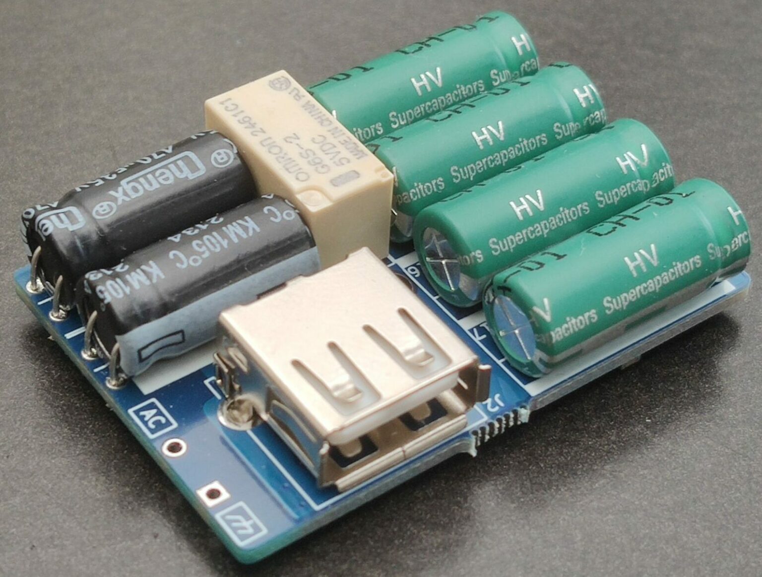
Now thats an interesting doodad. Ots a (bicycle) dynamo to USB charger. Notice the relay? The designer explained that:
On startup the rectified input charges the capacitors, once the voltage reaches 5V the relay disconnects the input and a MOSFET reconnects the input. Charging continues up to 10V, when the NOSFET disconnects the input and with some hysteresis reconnects to hold the 10V. The whole thing then goes through a buck converter etc.
The designer also explains this was done to not wear out the contacts on the relay.
So I take it that MOSFET and relay are in parallel. The designer wants the input connected through the MOSFET because they do not want to or can't shed load and because the MOSFET does not wear like the relay.
Sounds like the controller runs on 5V and they didn't find any other way to bootstrap it than the relay thing? Like what about depletion MOSFETS and I believe you'll find a couple of simple circuits that allow you to do this with an enhancement type too.
Can /ohm/ think of a reason why they would have done this?