/ohm/ - Electronics General: I am SiC edition
Thread got too loose:
>>2927795
>I'm new to electronics. Where to get started?
It is an art/science of applying principles to requirements.
Find problem, learn principles, design and verify solution, build, test, post results, repeat.
Read the datasheet.
>OP source:
https://github.com/74HC14/ohmOP
bake at page 10, post in old thread
>Comprehensive list of electronics resources:
https://github.com/kitspace/awesome-electronics
>Project ideas:
https://hackaday.io
https://instructables.com/tag/type-id/category-technology/
https://adafruit.com
https://makezine.com/category/electronics/
>Books:
https://libgen.is/
>Connector identification:
connectorbook.com
>Principles (by increasing skill level):
Mims III, Getting Started in Electronics
Geier, How to Diagnose & Fix Everything Electronic
Kybett & Boysen, All New Electronics Self-Teaching Guide
Scherz & Monk, Practical Electronics for Inventors
Horowitz and Hill, The Art of Electronics
>Recommended software tools:
KiCAD 6+
Circuitmaker
Logisim Evolution
>Recommended Components/equipment:
Octopart
LCSC
eBay/AliExpress sellers, for component assortments/sample kits (caveat emptor)
Local independent electronics distributors
ladyada.net/library/procure/hobbyist.html
>Most relevant YouTube channels:
EEVblog
W2AEW
Moritz Klein
>microcontroller specific problems?
>>>/diy/mcg
>I have junk, what do?
Shitcan it
>consumer product support or PC building?
>>>/g/
>household/premises wiring?
More rules-driven than engineering, try /qtddtot/ or sparky general first
>antigravity and/or overunity?
Go away
Anonymous
7/23/2025, 1:44:07 PM
No.2933539
>>2933537 (OP)
but can your SiC brick run Doop?
Anonymous
7/23/2025, 3:10:55 PM
No.2933553
>>2933560
>>2933663
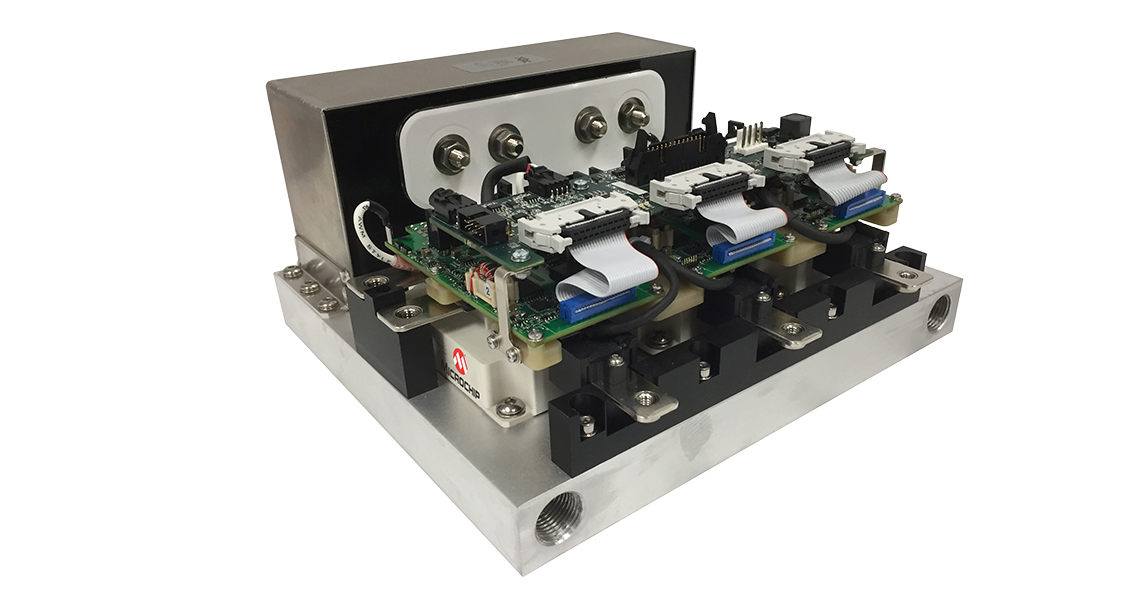
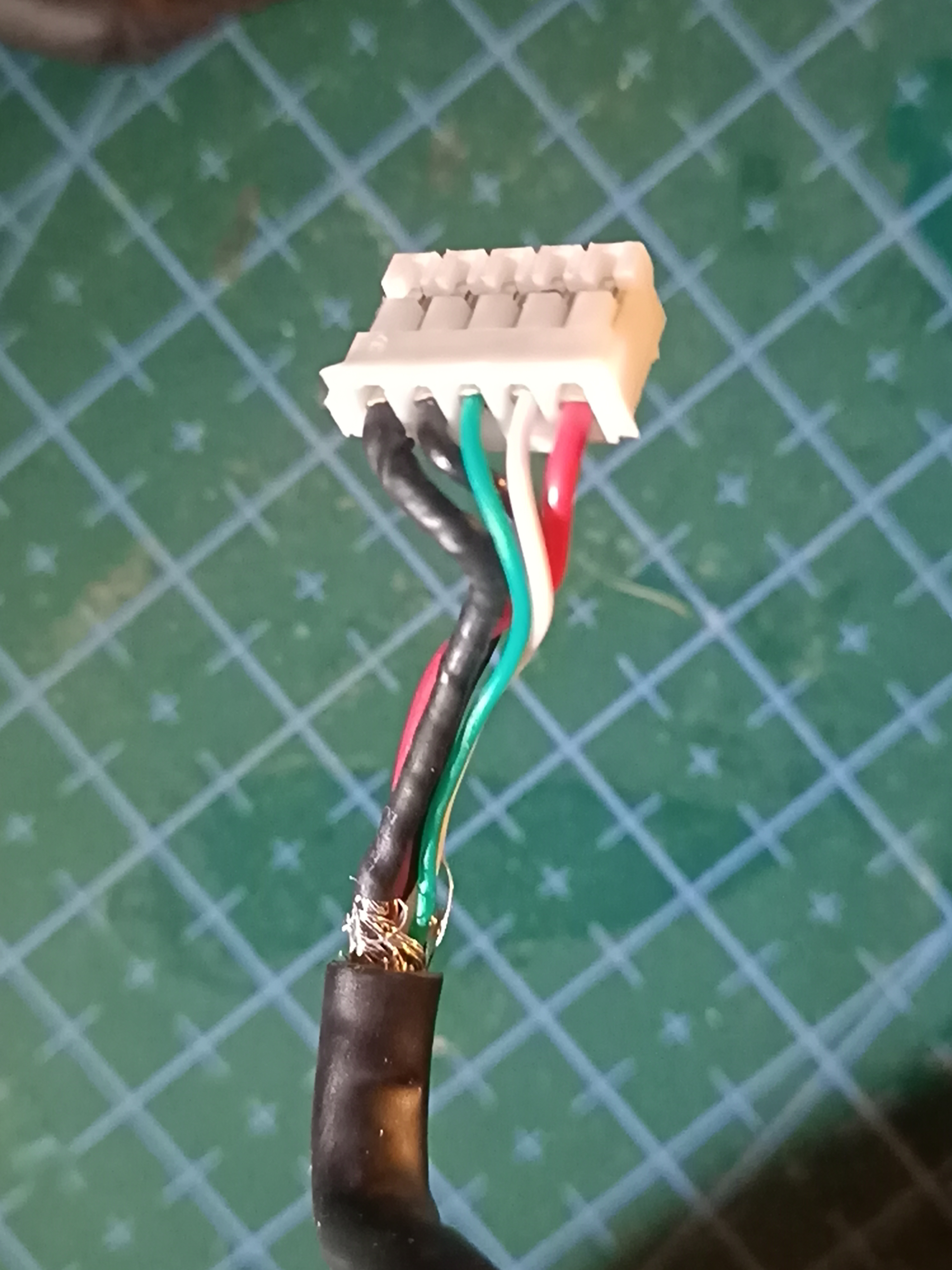
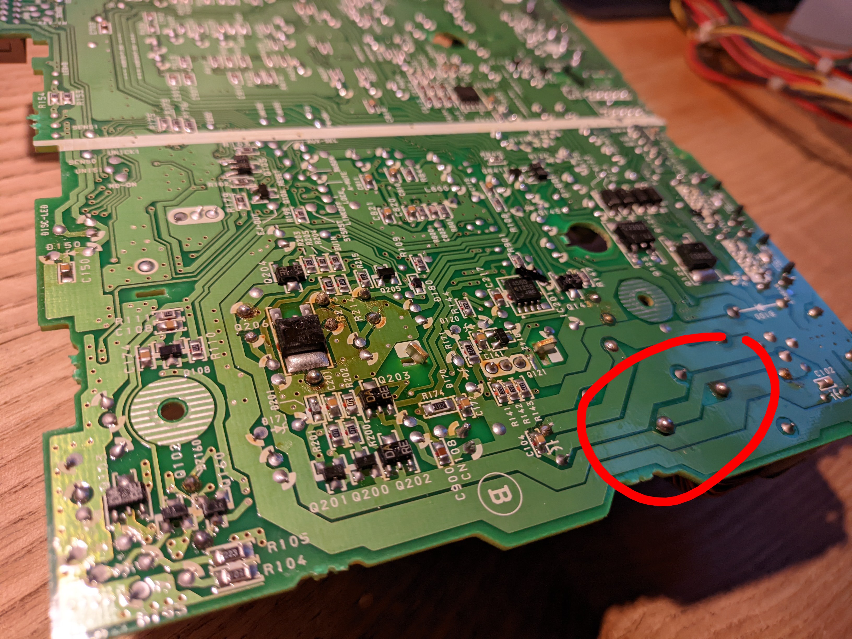
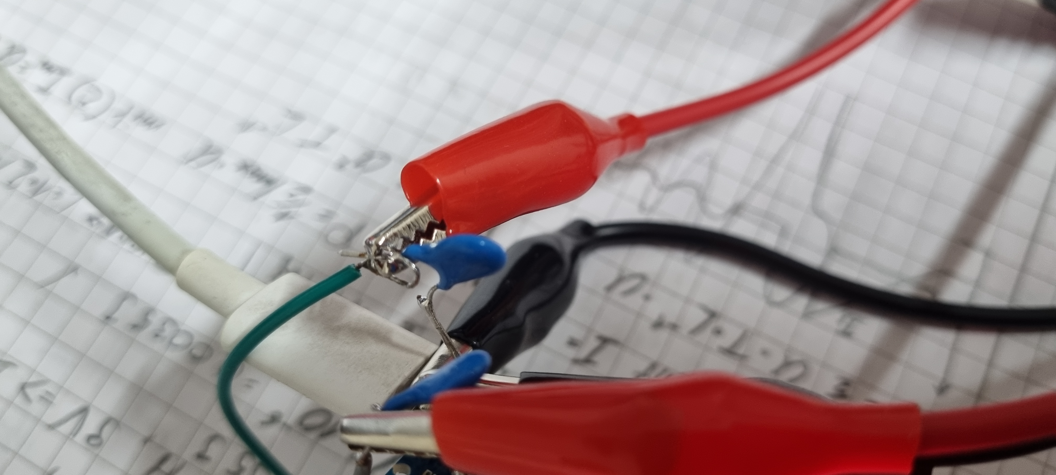
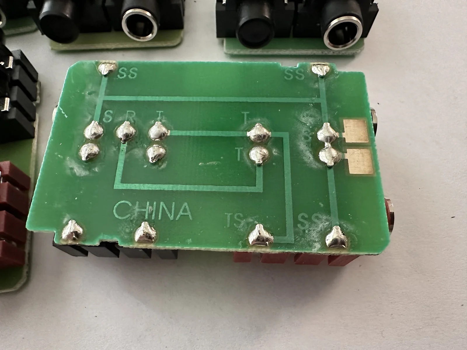
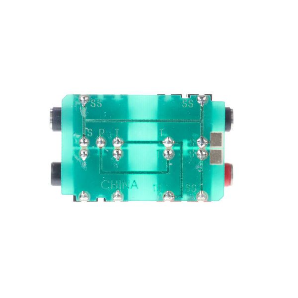
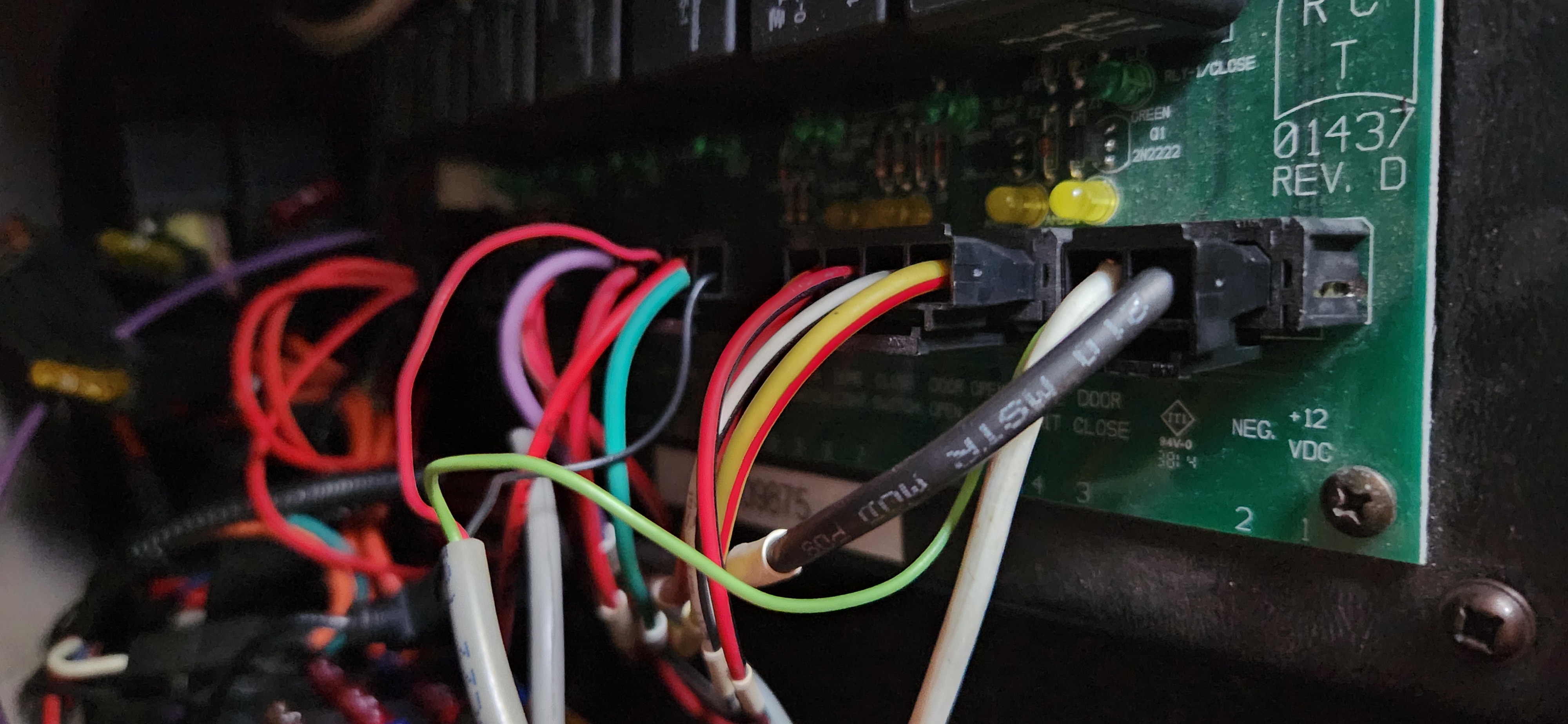
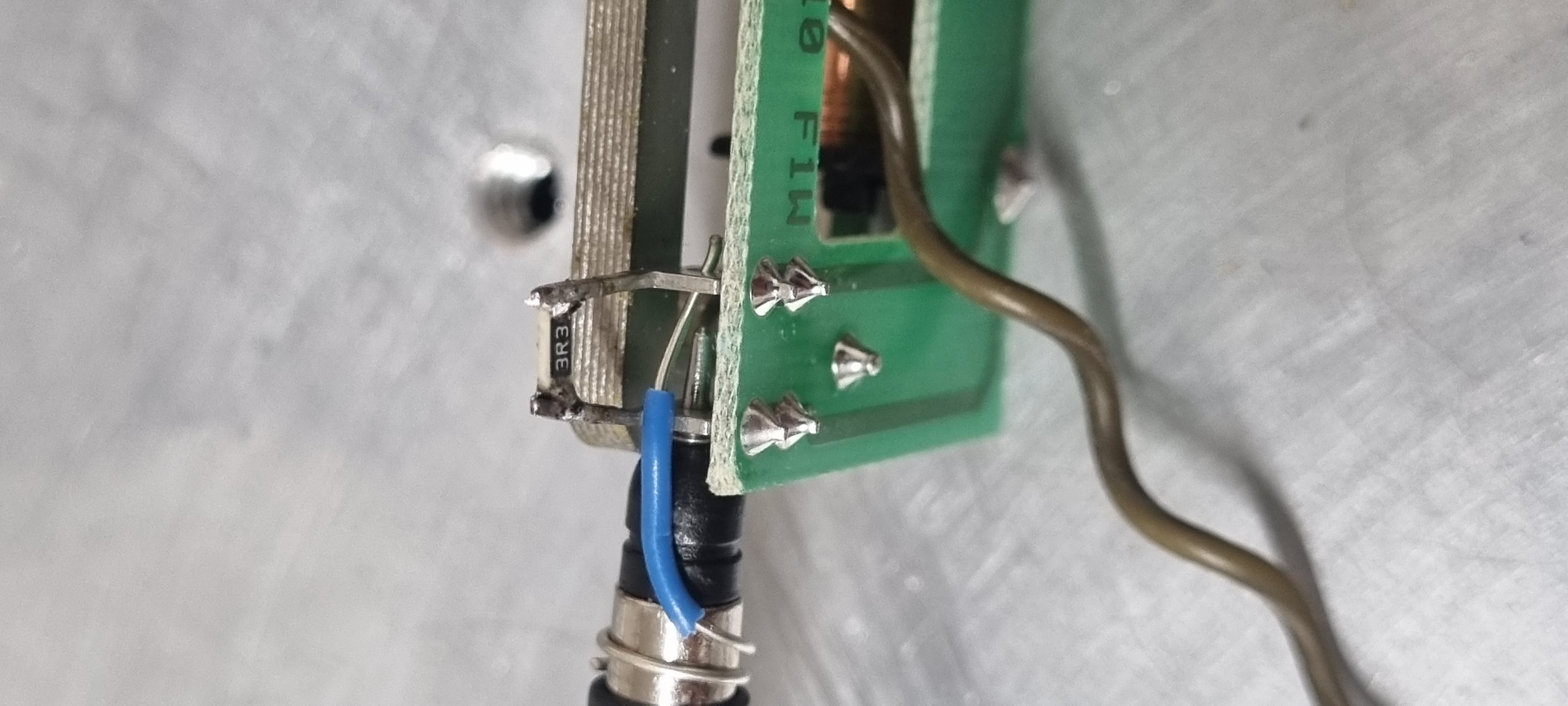
So I've managed to narrow down an intermittent continuity fault on the green wire. What can I do to fix it?
I was hoping to pull out the pin and draw out more wire/splice in a new section, but I don't know if its possible since it all goes into one cable. Ideally I don't want to fuck around with the other (good) wires.
>>2933161
GOOD NEWS, BOYS
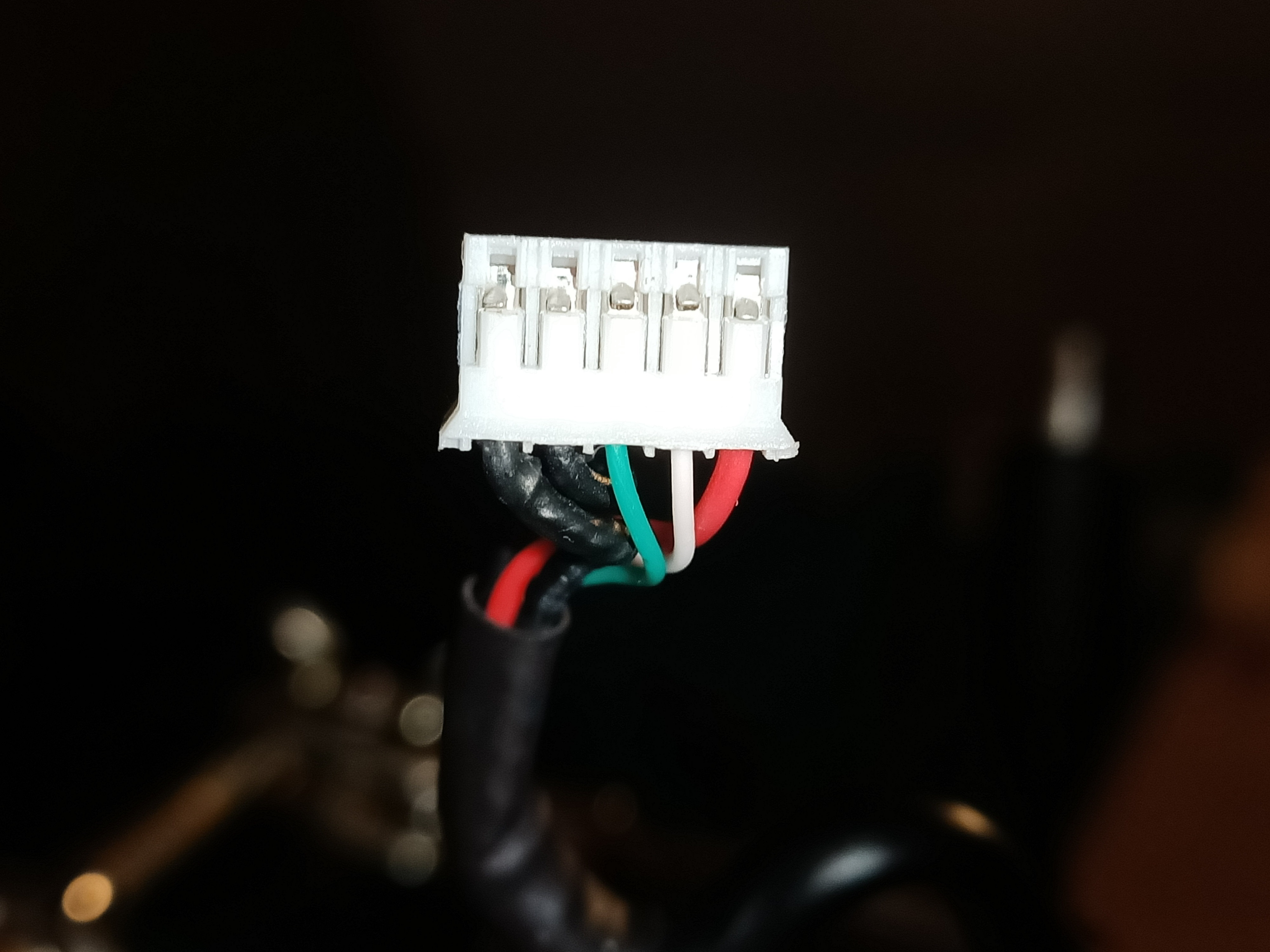
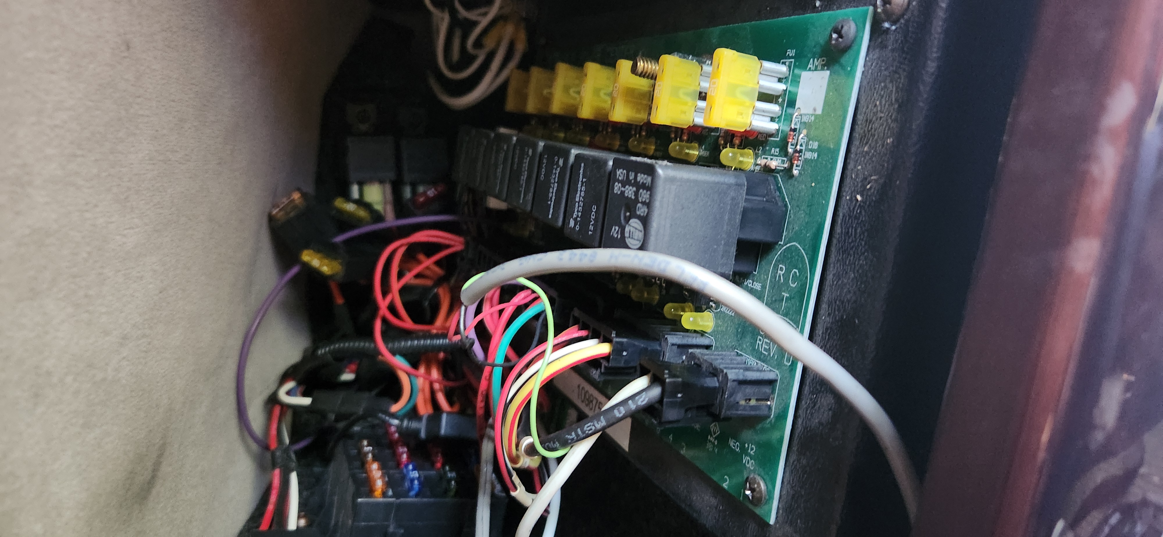
Seems like I got lucky. I was trying to figure out where things go, but it's near impossible to see, at least for my untrained eyes. So I just poked around a bit near the LED header and found J503 which is connected to a shunt and the 12V pin for the fans and LEDs. There is no connection through that 0-ohm resistor/jumper. Should be safe to just bridge it with whatever, yeah?
>>2933553
Where does the other end go?
Anonymous
7/23/2025, 3:54:57 PM
No.2933570
>>2933576
>>2933560
anon it is probable that something else wrong burnt that 0 ohm resistor. but at least you know where to look
Anonymous
7/23/2025, 4:27:31 PM
No.2933576
>>2933578
>>2933570
There's really only the LED daughterboard as the fans connect directly and work fine separately. I should probably test that, but it has a dumb micro connector.. I only tested the LED strips directly.
Anonymous
7/23/2025, 4:34:13 PM
No.2933578
>>2933585
>>2933576
Reflow the solder joints on the connector. Power up and touch the LED driver to find out if it's getting hot.
Anonymous
7/23/2025, 5:04:08 PM
No.2933585
>>2933587
>>2933663
>>2933578
Well, good thing I asked...
When I plug in the board, 12V is shorted to ground.
Anonymous
7/23/2025, 5:08:30 PM
No.2933587
>>2933623
>>2933585
U1 is probably dead.
Anonymous
7/23/2025, 6:58:30 PM
No.2933623
>>2933663
>>2933682
>>2933587
>U1 is probably dead.
much more likely it's one the MLCC caps
they're famous for going bad
to figure it out, one uses a current limited supply at 1-2A
then check what's getting hot using a FLIR camera, or alcohol, or dust from flux, your tongue, or the inside of your foreskin
Anonymous
7/23/2025, 10:12:28 PM
No.2933663
>>2933682
>>2933553
Connect a high-frequency oscillator / function generator output to the green wire. The higher the frequency and voltage the better, though if you can’t disconnect the other end from circuitry you’d better stick to sufficiently safe voltages (e.g. +/-0.5V). Then use a 10M oscilloscope lead referenced to the same ground as the function generator to slide alongside the wire and see where the capacitively-coupled signal drops off. You may need to tie the other side of the green wire to ground with a resistor. You may be able to do without a scope if your DMM’s AC voltage measurement can handle high frequencies, otherwise you could make a high input impedance buffer and peak detector on a breadboard with an op-amp and diode(s).
Test on a piece of wire so you know it works. Once you find where the break is, you can cut away the insulation there alone and perform a splice.
Otherwise you could consider spiral-binding a seperate green wire to the outside of the cable.
>>2933560
Bridge the 0Ω link with your DMM in amps mode, thats how I find faults.
>>2933585
Use a current-limited power supply to feed into this board. Could be a CC/CV benchtop supply, or it could be a 12V supply with a resistor in series. If you want 0.1A to go through it, you’re looking at a hundred ohms or so (2W). Then probe between the positive and negative rails throughout the PCB until you measure the lowest voltage. The lowest voltage will be across the shorted component(s). It’s possible the shorted path includes the inductor, so check that too.
>>2933623
Nah, my money is on the undersized switching converter IC too. Those things run hot, and in my experience MLCCs die open-circuit.
Anonymous
7/23/2025, 11:12:10 PM
No.2933682
>>2933803
>>2933623
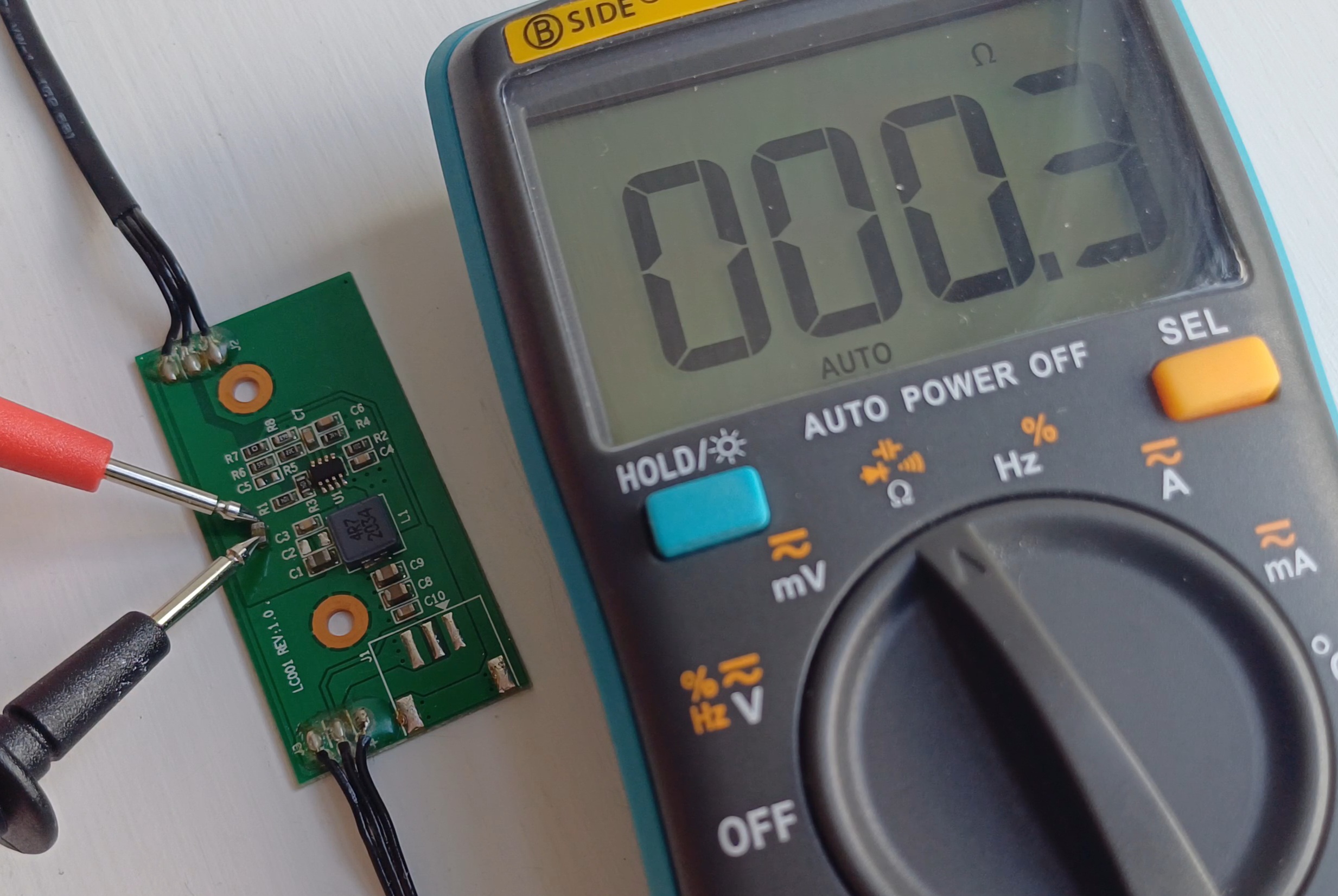
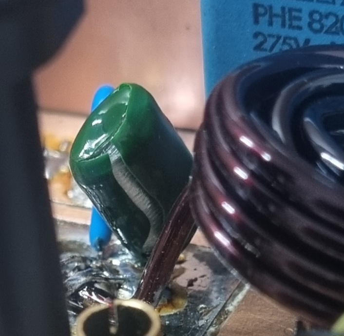
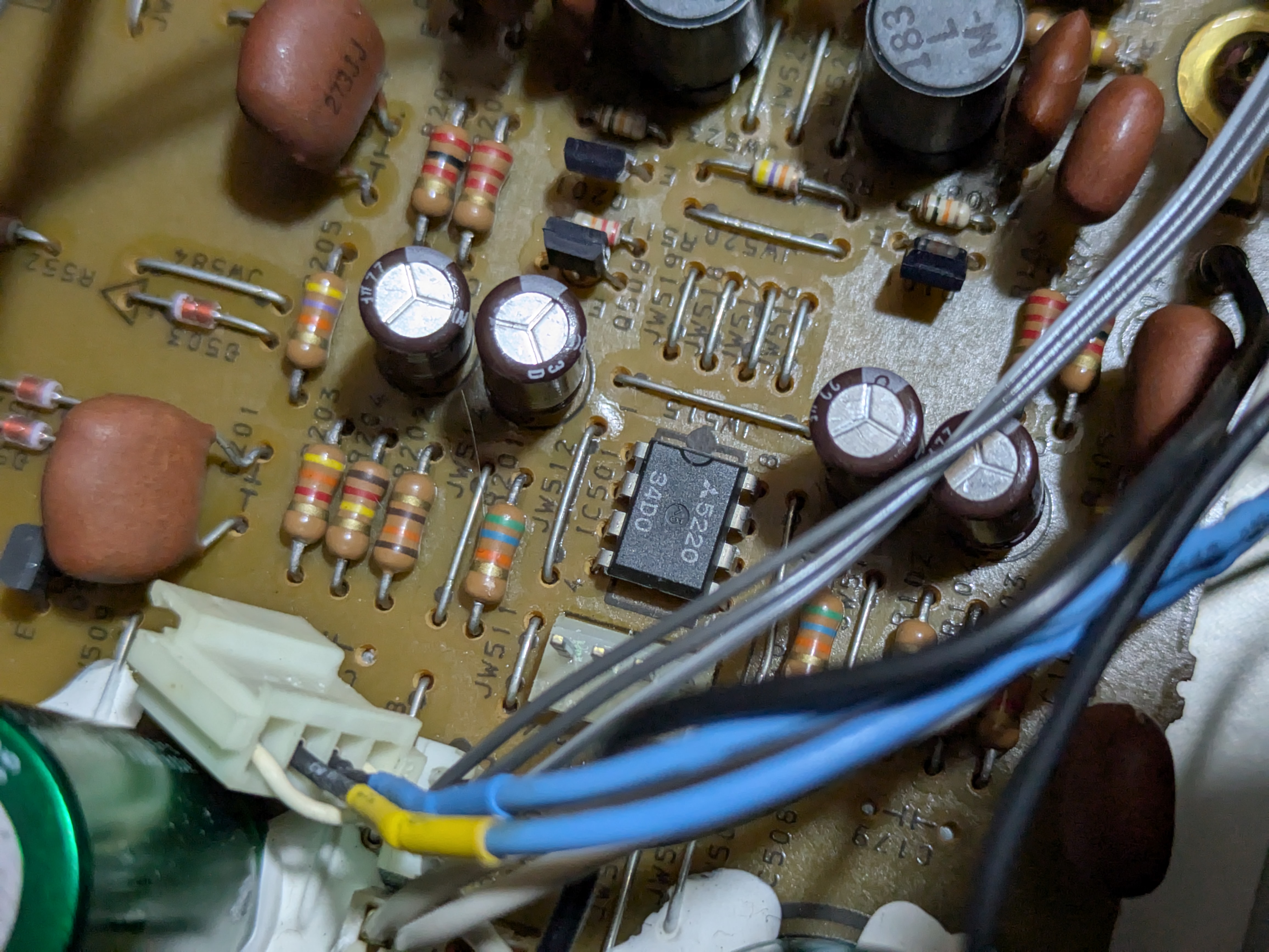
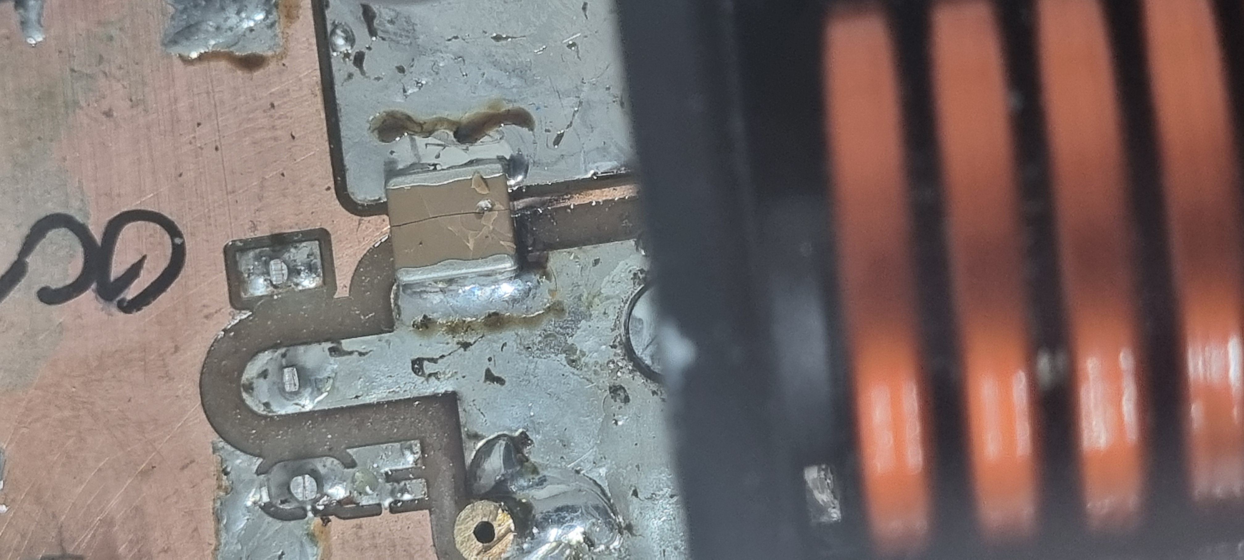
I think we might have a winner. C2 gets hot, and looks a bit wonky to boot?
>>2933663
>Bridge the 0Ω link with your DMM in amps mode, thats how I find faults
I don't have the equipment to power it outside of a pc, unfortunately.
>The lowest voltage will be across the shorted component(s).
I did try this, but maybe I'm not smart enough. C2 does measure slightly lower than its neighbors, so I think I'm going to try and tear it off tomorrow and see if it changes anything.
>>2933682
We do have a winner. C2 is a dead short.
The datasheet calls for 22µF input capacitor. The board has three input capacitors..?
Thoughts on where to go from here? I don't really have many parts lying around. Just some THT electrolytic caps.
Should I take off C3 and maybe C1 to check what they are (and turn a tarduino into a capacity meter to do so)?
Anonymous
7/24/2025, 1:47:08 PM
No.2933804
>>2933803
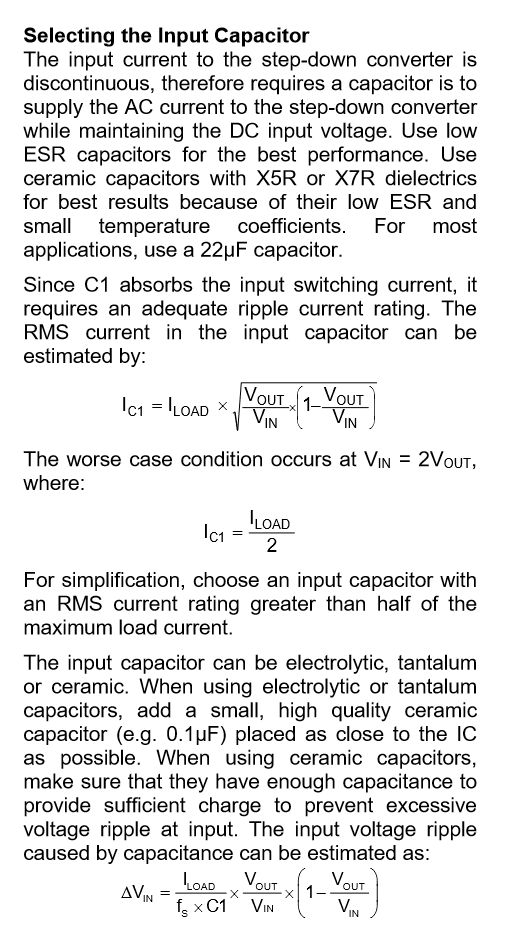
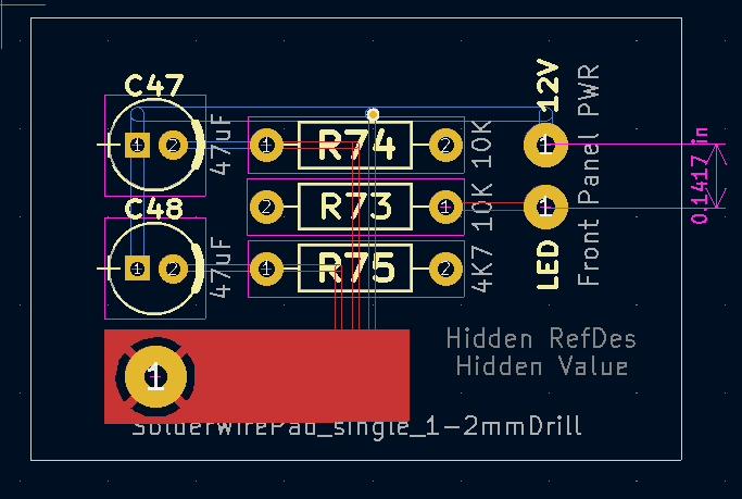
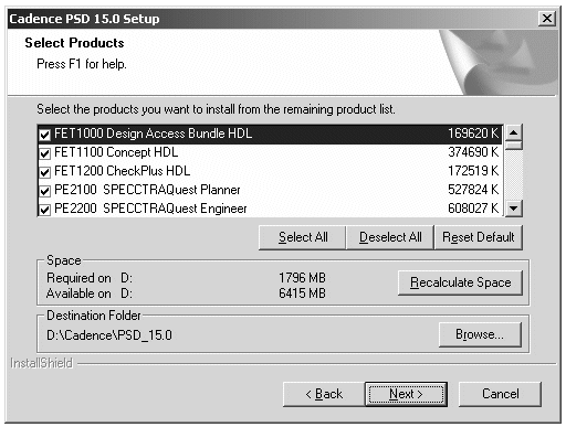
The relevant part of the datasheet for the MP1475 is here.
Anonymous
7/24/2025, 1:56:28 PM
No.2933805
>>2933803
It should work without the cap. There are 3 of them to reject more noise. Higher capacitance = low frequency, lower capacitance = high frequency.
Anonymous
7/24/2025, 2:01:10 PM
No.2933806
>>2933808
>>2933803
So you could take one off and measure, or you could figure out the probable value based off dimensions and voltage rating. I’d guess 25V but it could be 16V, I think it’s 0805? 10uF seems likely, and even if it’s smaller there’s no downside to 10uF, because that presumably makes the entire stack of three caps something like 10+10+2.2 or so, giving you your 22uF. You could maybe cram a 22uF in there, but in 0805 it would be tough to get in an appropriate voltage rating. You can try soldering the leads of an electrolytic cap (low-ESR preferred) in there, it will probably be electrically fine because you’ve got low-impedance ceramics in parallel, but mechanically it’s pretty easy to rip of little SMD pads unless you glue the solder joints.
For testing it will probably run without that cap, and it should definitely be fine short-term with an electrolytic.
Anonymous
7/24/2025, 2:14:25 PM
No.2933808
>>2933904
>>2933806
Yeah, it's an 0805. Seems like you can get them in 22uF at 16V though, but the 10+10+2.2 theory seems reasonable.
I do have an old scope so I suppose I could check out what the 12V looks like with some disco lights on or something?
Why would the electrolytic only be ok short term? I could hotglue things in place. I don't mind..
Anonymous
7/24/2025, 2:37:51 PM
No.2933812
>>2933813
>>2933560
>Where does the other end go?
USB. Seems to be the normal 4 wires + a shielded layer. Idk if I'm going to be able to pull a single wire out of that.
Anonymous
7/24/2025, 2:44:35 PM
No.2933813
>>2933904
>>2933812
Replace the whole cable or install a USB socket in the device and connect with a patch cable.
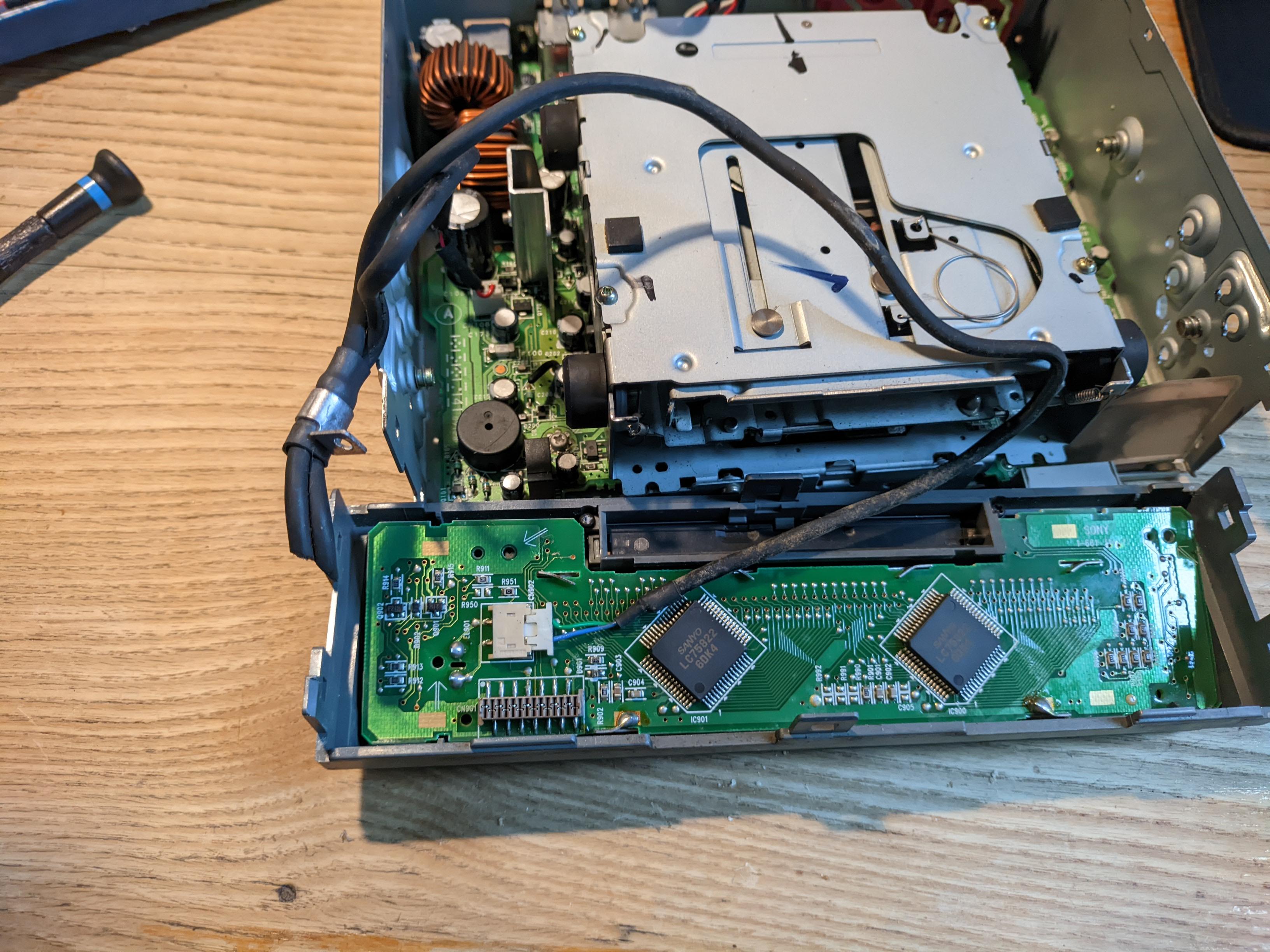
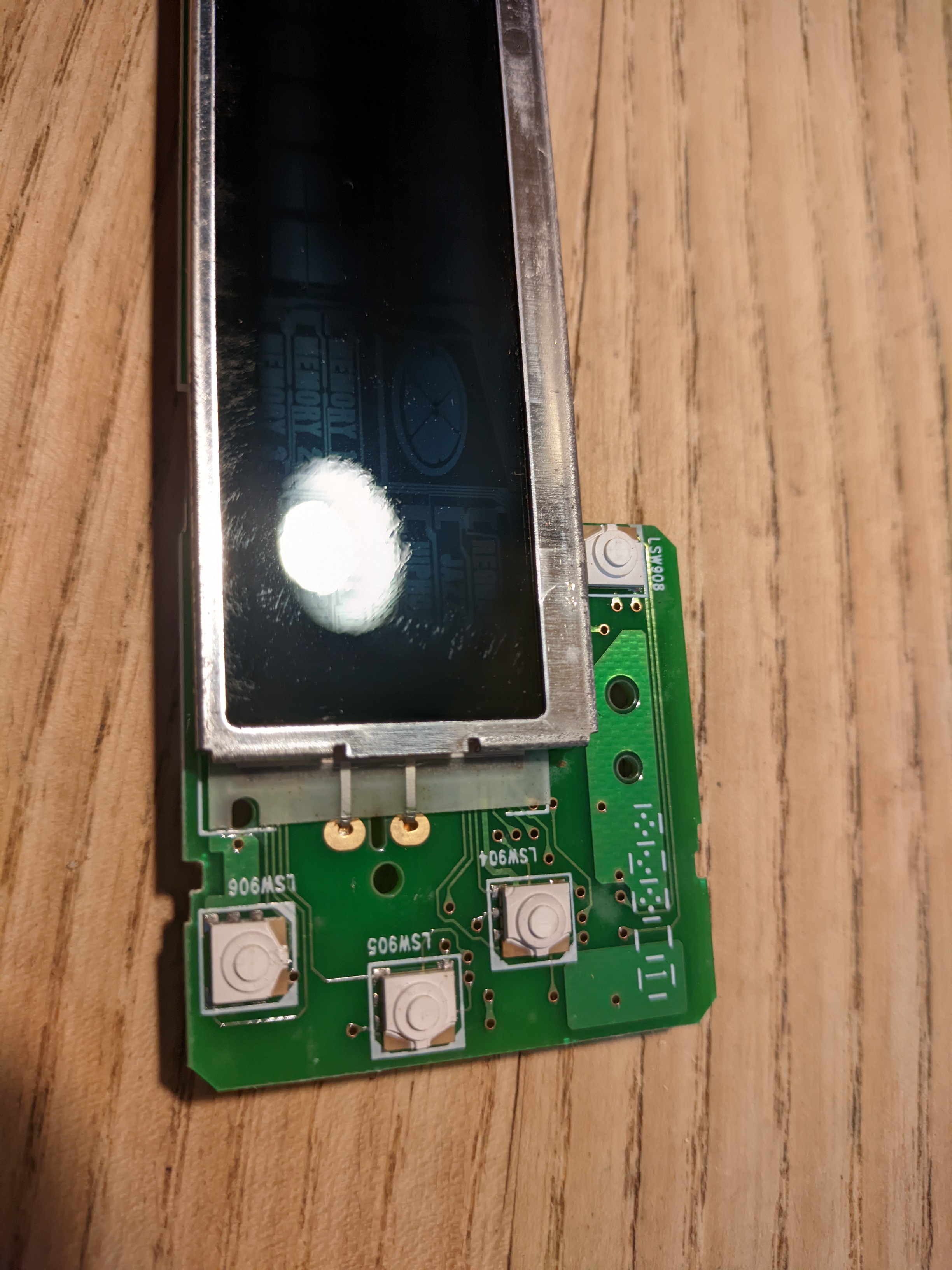
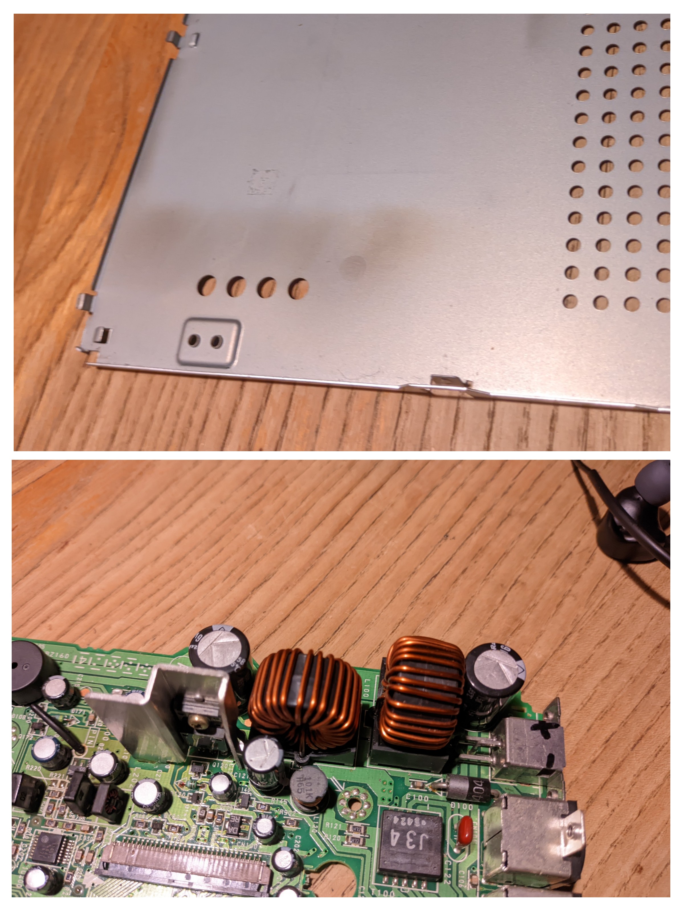
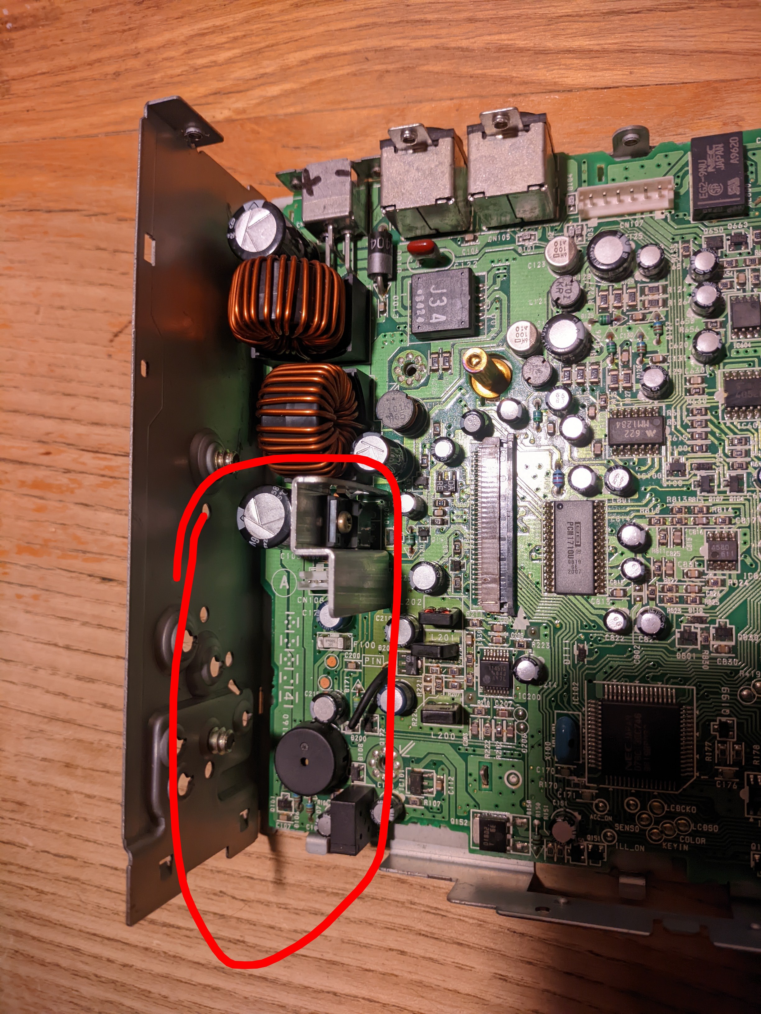
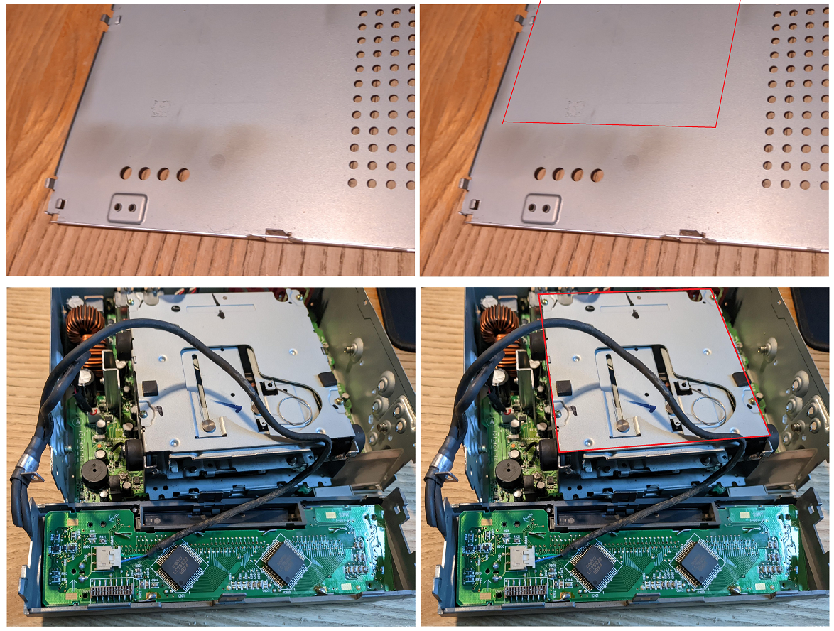
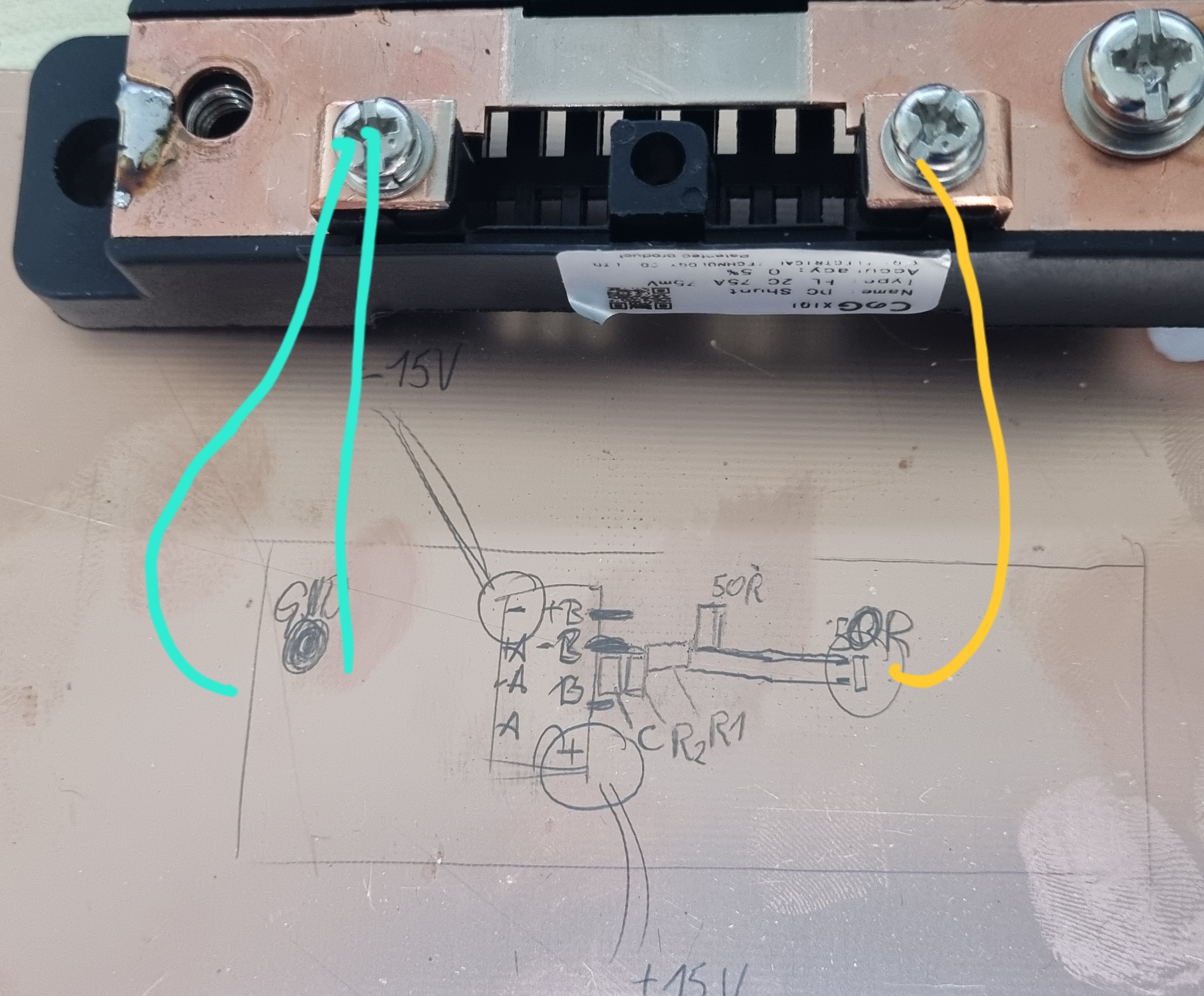
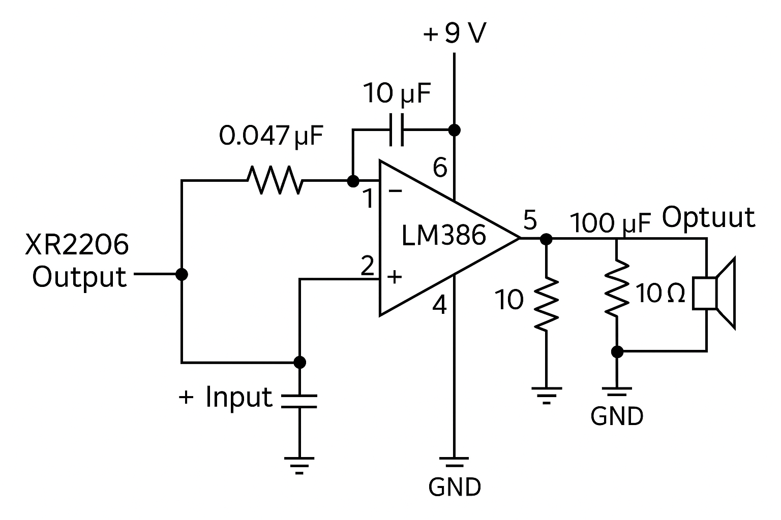
Electronics noob here, trying to bring an old automotive MD player/graphic equalizer (Sony MDX-700EQ). It came into my hands with all the wires cut off. No big deal, I thought. However I soon found out that this particular model came with an external inverter box, which I am missing. After opening up the MD player and examining it, I now know that two wires from the missing inverter go to the main board, and the remaining two - to the faceplate, which contains an LCD display and some buttons.
Google tells me that LCD displays use AC power, so it makes sense to me that it would require an inverter, as car electronics are ran off 12VDC. Am I on the right track?
In this case the LCD is driven by two LC75822E drivers. I have located its datasheet online, but Idk how to read it. The table says it requires a voltage anywhere from 3 to 6.5V, does that mean I could theoretically rig up a 12VDC to 5VAC inverter (if it's even a thing) and it should work?
Here's the datasheet for the LCD drivers:
https://ksp-electronics.com/media/43160/lc75822e_w.pdf
>>2933830
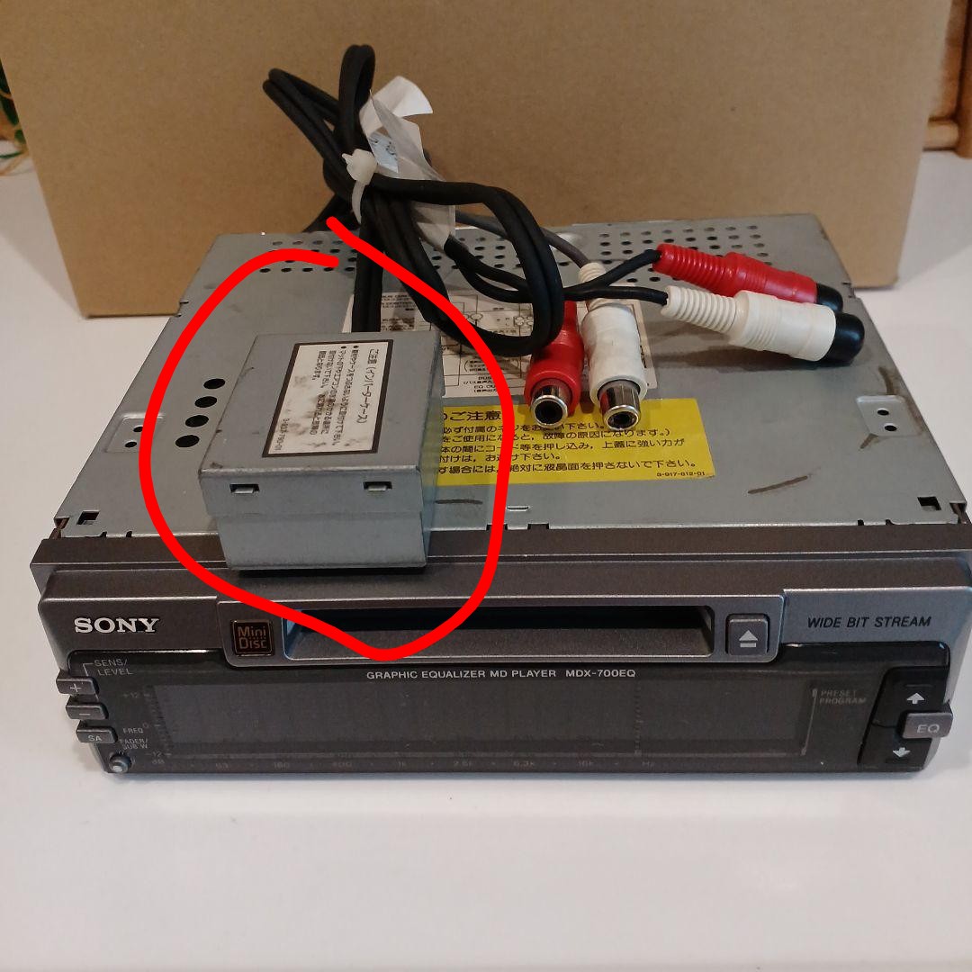
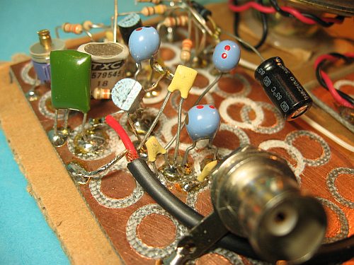
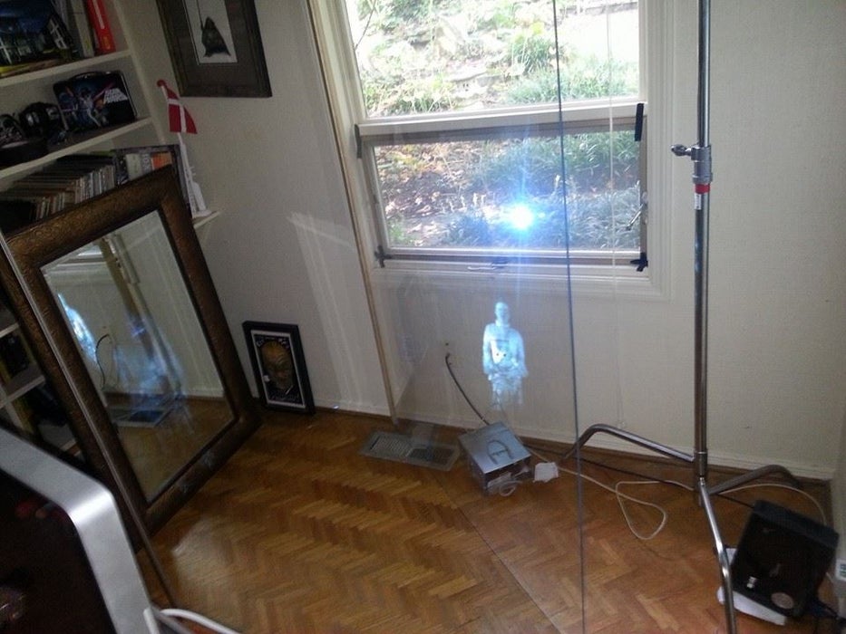
Update, in my desperation I've consulted ChatGPT and it told me that this missing inverter would actually be used to power the backlight of the LCD. Sure enough, the pins of the connector on the faceplate go straight to what seems to be the LCD backlight (pic related). AI has determined the type of backlight to be EL. All this actually seems to be correct, but how do I choose what EL inverter to buy and how do I not cook the backlight? I don't know what voltage and frequency it requires :(
Anonymous
7/24/2025, 7:53:37 PM
No.2933863
>>2933875
Anonymous
7/24/2025, 8:36:24 PM
No.2933875
>>2933887
>>2933863
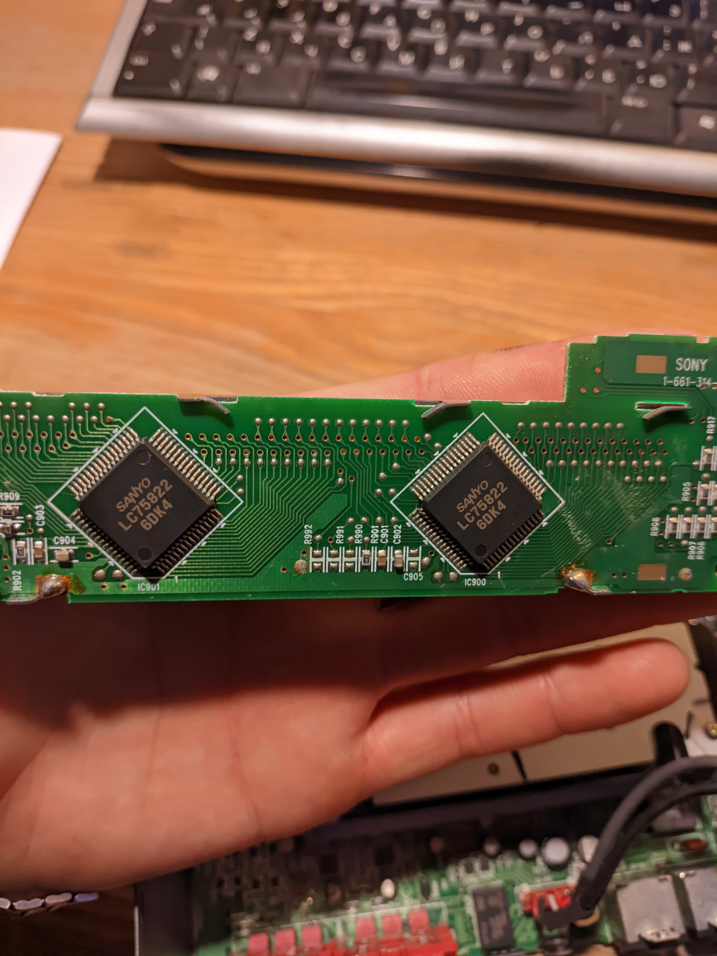
Would a VFD display use LCD drivers (pic related)?
Anyways who do I give it back to? The Japanese wrench monkey who didn't bother to unplug any wires from the car that he was taking apart and just cut them off, then proceeded to put everything he salvaged up for sale on Yahoo auctions?
Anonymous
7/24/2025, 10:02:48 PM
No.2933887
>>2933892
>>2933830
>>2933847
>>2933875
Hello fellow MD nerd. I have one of those units. Let me take some pics for you.
Anonymous
7/24/2025, 10:15:02 PM
No.2933892
>>2933931
>>2933887
Hi, that's awesome. Better than just taking pics, if you somehow connected an oscilloscope to the output side of the inverter (pic related), that would be incredible.
Anonymous
7/24/2025, 10:44:48 PM
No.2933904
>>2934014
>>2933808
High ripple current can overheat higher ESR capacitors, leading to shorter lifetimes. That’s the only long-term issue with electrolytic caps in place of MLCCs.
>>2933813
Seconding this. USB B panel mount sockets are cool, C sockets are ok if it needs to be compact I guess.. It’s quite likely that the unbroken wire is just after the strain relief of the USB end itself, so not likely to be easy to repair.
>>2933847
From what I know about electroluminescent displays, they like about 1kHz and in the realm of 100V. If you have a high voltage function generator you could test that directly, if not there’s definitely ways of coupling your phone/computer’s aux-output with an audio amplifier and then probably a big audio transformer to step up the voltage.
Before you do any testing though, I’d look at at least 5 different EL LCD display module datasheets, assuming you can’t find one for your current display. If you’re lucky they’re all about the same, maybe current requirements go up by display size which is easy to factor out.
It’s also an option to disassemble the display to extract the EL backlight panel and replace it with some sort of LED diffuser, but it wouldn’t be easy.
Anonymous
7/24/2025, 11:56:48 PM
No.2933931
>>2934015
>>2933892
I don't own a scope but I'll take pics. Often those are DC-DC up converters for VFD displays running 19v (maybe more?). But they have additional wiring pins so theirs likely some coordination and communication going on, not just dc-dc boosting.
https://filebin.net/rw0y21atw76w3gaq
Sony definitely made a service manual for this unit, but its rare to find them for units that werent sold outside Japan. Somewhere there exists a PDF with really good wiring diagrams and pinouts and probably diagnostic procedures as well. Maybe try searching on yahoo auctions japan and mercari.
Anonymous
7/25/2025, 12:30:42 PM
No.2934014
>>2933904
>High ripple current can overheat higher ESR capacitors, leading to shorter lifetimes.
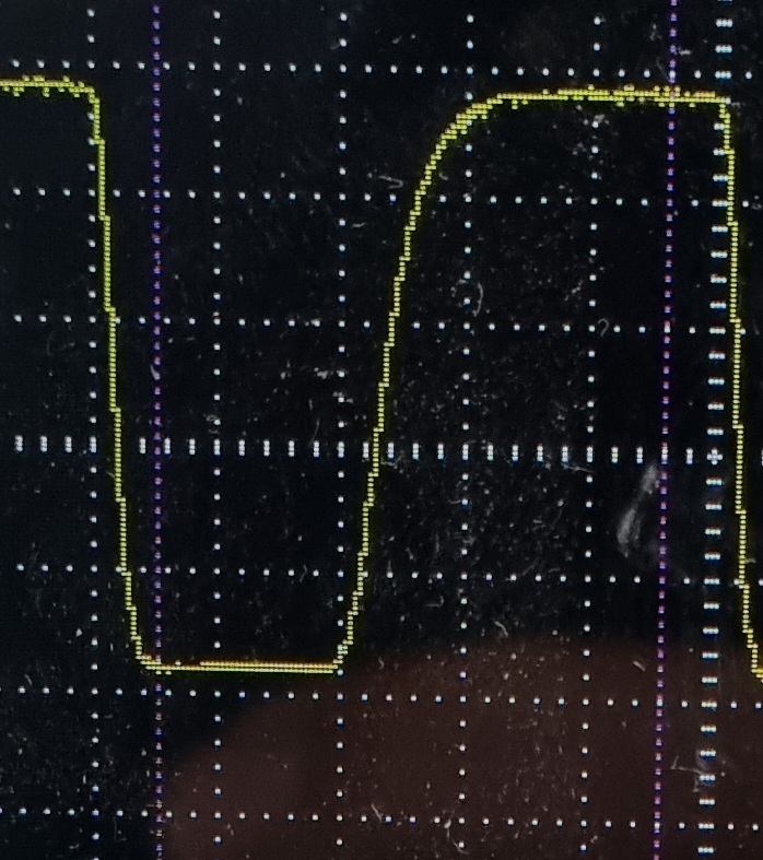
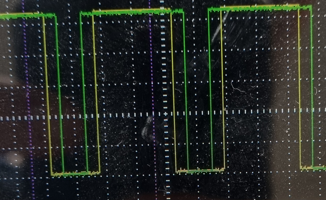
I see. WELL, I'm getting around 15 mV of ripple at full blast (1.1 amps @ 12V), and around 50 mV or so if I strobe the lights, but it's an old analog scope that I don't really know how to use for this type of thing. Not sure if this information is even useful.
Gonna bridge that 0-ohm resistor and put everything back together for now.
Anonymous
7/25/2025, 12:40:35 PM
No.2934015
>>2934027
>>2933931
I can't tell you how gracious I am for your help. This board rocks.
I've only been able to find a simple user's manual for this unit. Maybe it would be worth trying to contact Sony directly, though I doubt they would be of any help.
As for the display type, we're positive this is an LCD, not a VFD, right? There are LCD driver chips on the circuit board. Also, the user's manual labels the module that I'm missing as "inverter". Though I've also looked at user manuals of other similar Sony units and some of them have similar external modules that are labeled "DC-DC converter". I assume these units have VFD displays.
Oh and this could be a stupid thought, but some multimeters have a frequency setting, don't they? Maybe you have one and it could be used to measure the output of the inverter module? Just a thought.
Anonymous
7/25/2025, 1:05:08 PM
No.2934027
>>2934123
>>2934015
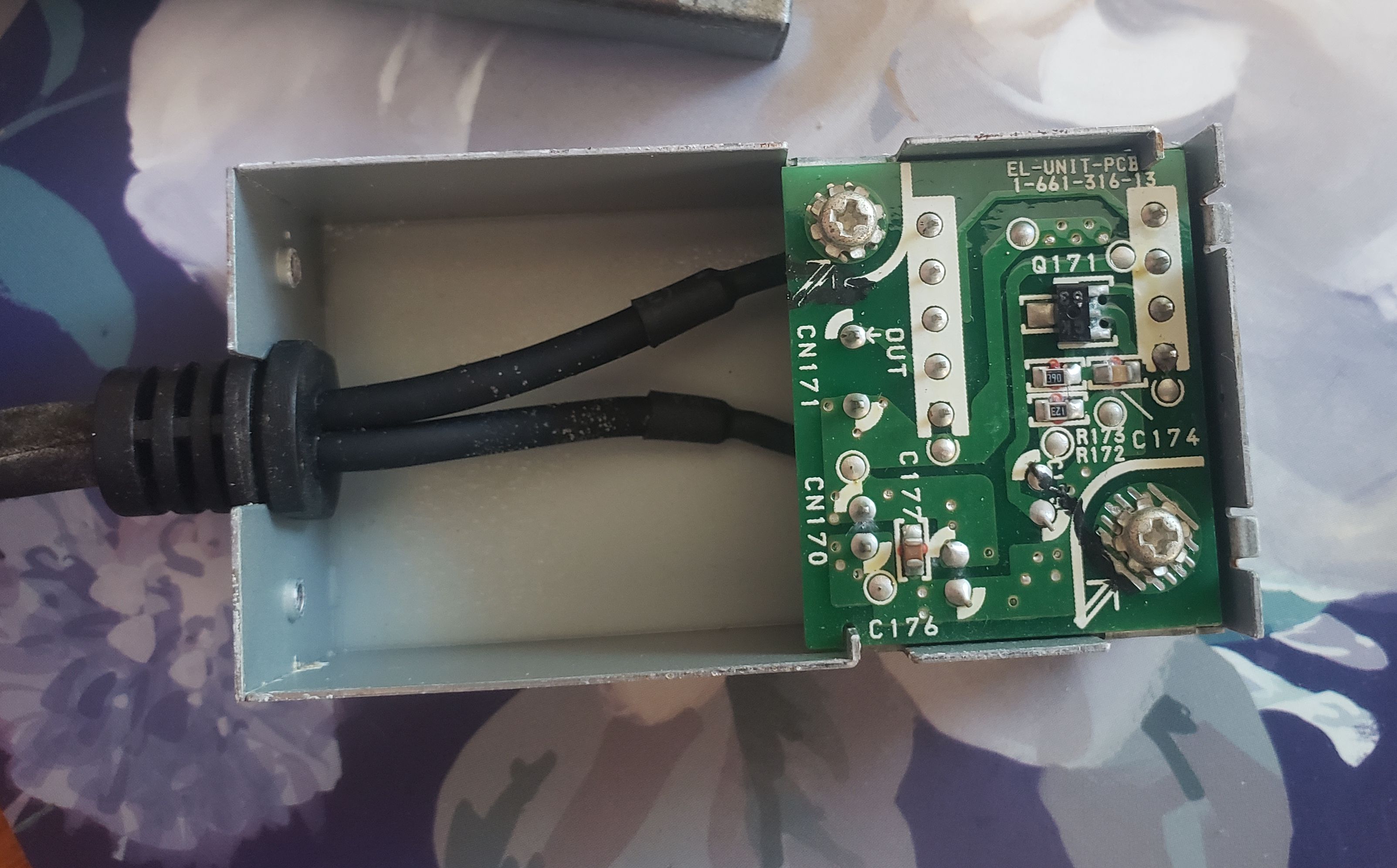
The PCB saying "EL-UNIT-PCB" suggests it's an EL drier alright. Because there's just a single SOT-89 semiconductor unit with transformer and passives, either that's a strange joule-thief-type oscillator, or it's being driven from the main board. Measure the wires that went into it I guess (a 1k burden resistor would help), if they're flat DC you have your answer.
Couldn't find a definite SMD code for CK (or is it GK?), maybe someone should write a reverse image search algorithm that compares the writing and footprint to the thumbnails on Octopart and LCSC. I'm seeing transistors, voltage regulators, and voltage detector ICs. Probably a transistor.
I'd trace the circuit board (and hopefully get some help in probing the transformer windings) to see what topology the transistor is in. Compare it to the shitty EL wire inverters powered by AA batteries that use a single transistor, it might look pretty similar.
Anonymous
7/25/2025, 2:28:26 PM
No.2934038
>>2934107
>>2930063
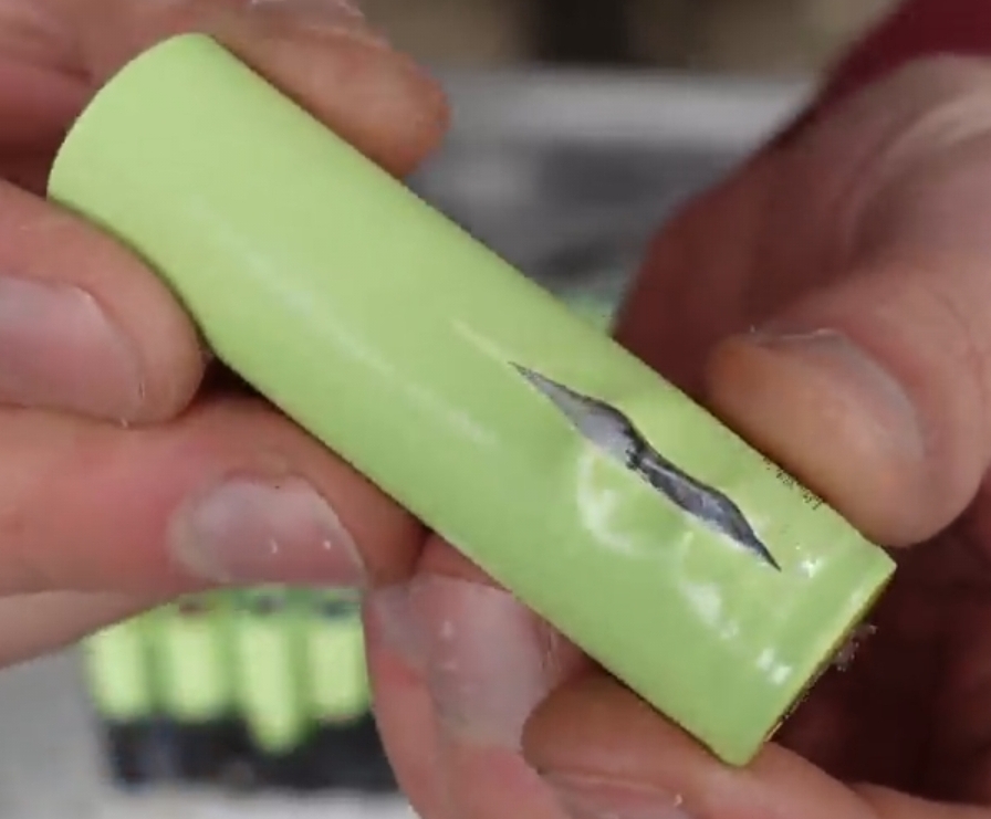
okay so i balanced charged each of those cells (they are connected in series) to 4.2V and they all held the voltage but then i haven't used the battery at all and two weeks later it's dead again, the cells are like 2x 3.2V 2x and 1x 0.5V so i am pretty sure they are cooked.
WHat surprised me that all of the cells are dead? the battery pack is not that old like 4 years and i rarely used it. But i expect like one or two cells to be dead but all of them? They aren't bloated or anything.
But either way changing them would be poinstless since they are welded in and make up 90% of the battery pack price so might as well buy a whole new one at this point.
Anonymous
7/25/2025, 7:39:19 PM
No.2934107
>>2934127
>>2934038
18650s don't swell, they just die. Especially when they've been discarged deeply for a long time.
If you can get a new genuine pack for only slightly more than quality cells, then go ahead. Sounds odd, but yeah.
Anonymous
7/25/2025, 8:50:29 PM
No.2934123
>>2934128
>>2934027
Welp, I connected the board to a power source and what do you know - nothing happened. The display did not come on and the MD mechanism didn't do anything when I pressed the eject button. The connector that is supposed to be supplying power to the inverter seems dead as well. It showed 2.8V and falling at first, so I disconnected the power source, shorted the pins of the connector, connected the power source again and it now shows 0.22V. I guess there was some leftover charge in one of the capacitors.
Not entirely sure if it's broken or it just doesn't do anything until you connect it to a master unit via bus cable.
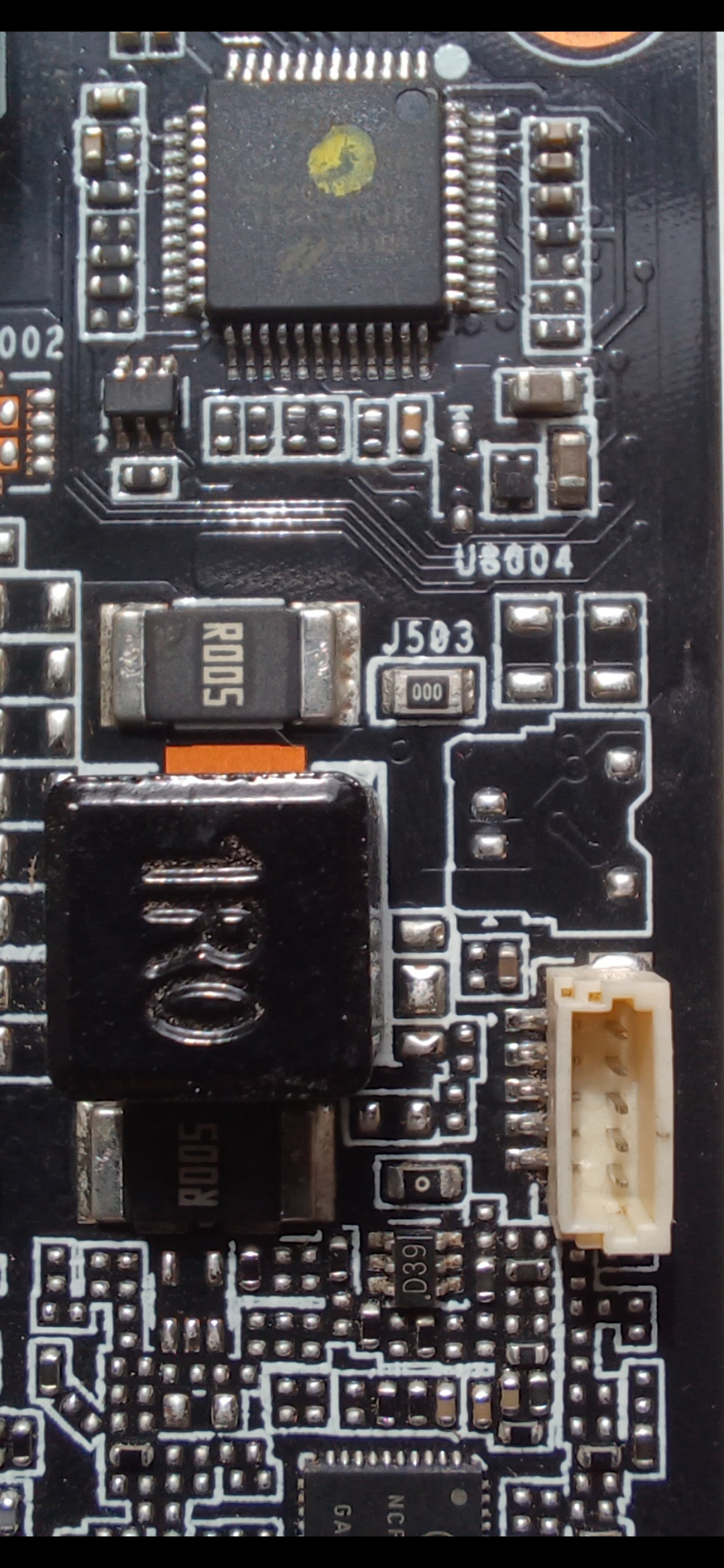
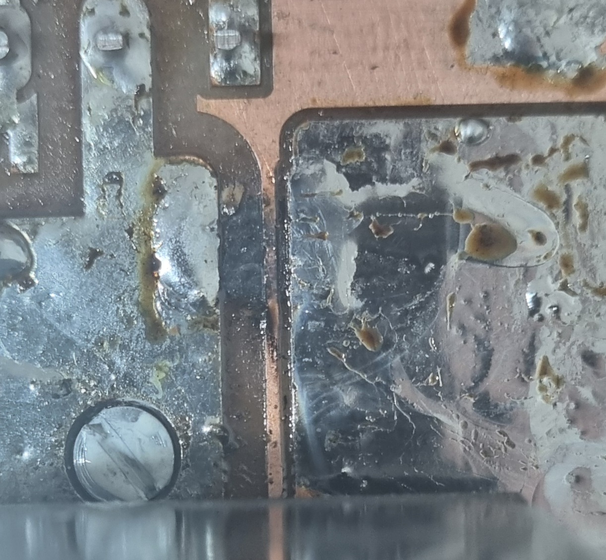
Also I've noticed a residue on the board and some cold joints on the big inductor coils (circled in my pic). Does that look like water damage, or flux residue from a prior repair?
Anonymous
7/25/2025, 8:56:22 PM
No.2934127
>>2934167
>>2934107
doesn't that depend on the chemistry mainly and not really the form factor?
Anonymous
7/25/2025, 8:58:49 PM
No.2934128
>>2934129
>>2934123
Yes, it looks like someone made some shitty solder joints in that area. Do you see the discolored area of the board to the left of your red circle?
Anonymous
7/25/2025, 9:16:28 PM
No.2934129
>>2934130
>>2934128
Yeah, that area is what I was wondering about. Not sure if it's water damage or flux residue from prior repairs. I guess it's the latter then
Anonymous
7/25/2025, 9:21:57 PM
No.2934130
>>2934131
>>2934132
>>2934129
It looks like it got hot. I suspect that MOSFET or regulator is on the fritz.
Anonymous
7/25/2025, 9:24:49 PM
No.2934131
>>2934132
>>2934130
Also, remove the solder spheres and redo those joints. Clean the board with IPA so you can see what's happening.
Anonymous
7/25/2025, 9:29:05 PM
No.2934132
>>2934135
>>2934131
>>2934130
Thanks for the tip, will do.
Now that you mention the board possibly getting hot at some point, there is evidence of it on the metal case. Will have to do some investigating (to the best of my limited ability).
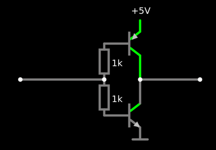
This capture is from ST 3-quadrant triac application note. Why did they choose to reverse the NPN and PNP from the usual push-pull configuration (high-side NPN & low-side PNP)?
Anonymous
7/25/2025, 9:38:38 PM
No.2934135
>>2934140
>>2934132
looks like a dirt shadow to me. is there something square-shaped like that sitting up against it?
>>2933830
hmmm
Anonymous
7/25/2025, 9:44:05 PM
No.2934138
>>2934139
>>2934133
It's more efficient, but comes with certain caveats. The base voltage for the two BJTs must be kept at VCC or GND at all times or the transistors will short out the supply rails because current will flow through the PNP's base into the NPNs base and both will conduct. The transistors will also still short out anyways while the base drive voltage is transitioning from low to high but if the rising edges are fast enough this is not a problem. The base drive voltage absolutely must go right up to VCC and right down to GND and operation in the linear region like a normal push-pull is not possible so this output stage cannot output analogue voltages.
Anonymous
7/25/2025, 9:46:55 PM
No.2934139
>>2934133
>>2934138
Forgot to mention the primary advantage of this setup and the reason it's more efficient compared to a traditional push-pull is that the output voltage goes up to the rails and there's no base-to-emitter junction 0.7v loss.
Anonymous
7/25/2025, 9:48:18 PM
No.2934140
>>2934217
>>2934135
Not at all, the darkened area on the case corresponds to this part of the board. Could it have been the big transistor with the heatsink (I think that's what that is) that released the magic smoke?
Anonymous
7/25/2025, 9:51:46 PM
No.2934141
>>2934133
I think the image might actually be wrong because without a resistor in series with each base there is nothing preventing the two transistors from shorting out. I think it should look like pic related
Anonymous
7/25/2025, 11:41:17 PM
No.2934163
>>2934204
>>2933560
We did it, boys.
Moral of the story? MLCC's can indeed fail short and take what was once a very expensive GPU out of service, and for what? Some silly christmas lights..
Appreciate the help.
Anonymous
7/25/2025, 11:59:17 PM
No.2934167
>>2934913
>>2934127
Nah. It's a metal cylinder. They have a safety vent if pressure does rise so they don't explode.
Anonymous
7/26/2025, 12:07:03 AM
No.2934170
>>2934205
Would a fault like this lead to a short, eventually? She's still fine and the capacitance is still there. But a short would be really bad news. I think it's radiant heat from an adjacent part.
Anonymous
7/26/2025, 2:46:09 AM
No.2934204
>>2934290
>>2934133
Bet it’s an accident, slap-dash work from an intern. What happens when you power up your circuit and your MCU output pin is hi-Z during startup? Current flows from +5V to GND through the bases and instantly kills the transistors from shoot-through current.
No way do you need to worry about a 0.5V difference in output voltage when driving a TRIAC, especially not when driving it with an AC-coupling cap.
>>2934163
Cool stuff, I was wrong about the failure mode after all. I wonder why they’re using a zero-ohm link in the first place? It couldn’t have been acting as a fusable resistor, could it? If it’s what blew when the cap shorted, maybe you want to replace it with a fuse.
Also those RGBs are disgusting. You make me want to take my GPU and RAM sticks out and surgically disable the RGB lights, but considering I couldn’t even disable the RGBs on a cheap case-fan without killing it I think I’ll pass.
Anonymous
7/26/2025, 2:49:54 AM
No.2934205
>>2934248
>>2934318
>>2934170
Potentially, I wouldn’t say that it couldn’t lead to a short. I’d want to relocate its replacement, or at least add some heat shielding between it and the heat source.
Anonymous
7/26/2025, 3:47:38 AM
No.2934217
>>2934140
sorry, when i said "sitting up against it", the "it" i was referring to was the negative space, i.e. the part of the lid that *wasnt* darkened. hopefully pic rel clears it up.
its very possible that something is blown in your circuit, but i wouldnt count on that dark shadow for evidence of that. it really just looks like dirt/dust, or maybe faster oxidation from increased airflow. i mean, you can literally see it go all the way around the lid.
Anonymous
7/26/2025, 7:11:57 AM
No.2934248
>>2934205
Turns out the heat is generated within.
Anonymous
7/26/2025, 2:03:16 PM
No.2934290
>>2934204
>It couldn’t have been acting as a fusable resistor, could it?
I mean it did, but from my research it was by "luck" and not design. I say luck because I don't know what would have happened if it hadn't blown. As the PCB says it's just a jumper, and the reason for the 0-ohm resistor is that the pick and place machine can handle it like any other resistor. Allegedly.
>I couldn’t even disable the RGBs on a cheap case-fan without killing it I think I’ll pass.
I can imagine.
You have to hook up the CPU fan in the picture with a USB cable and install software to disable the lights...
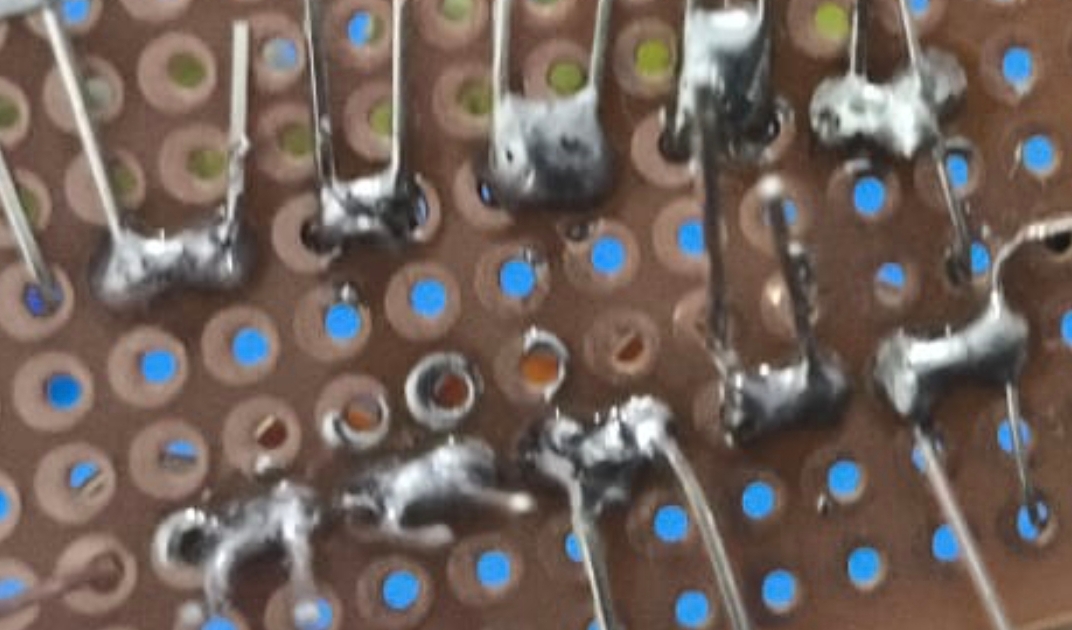
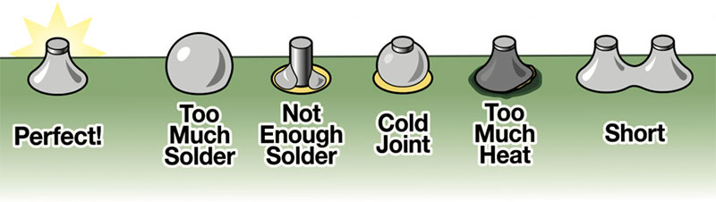
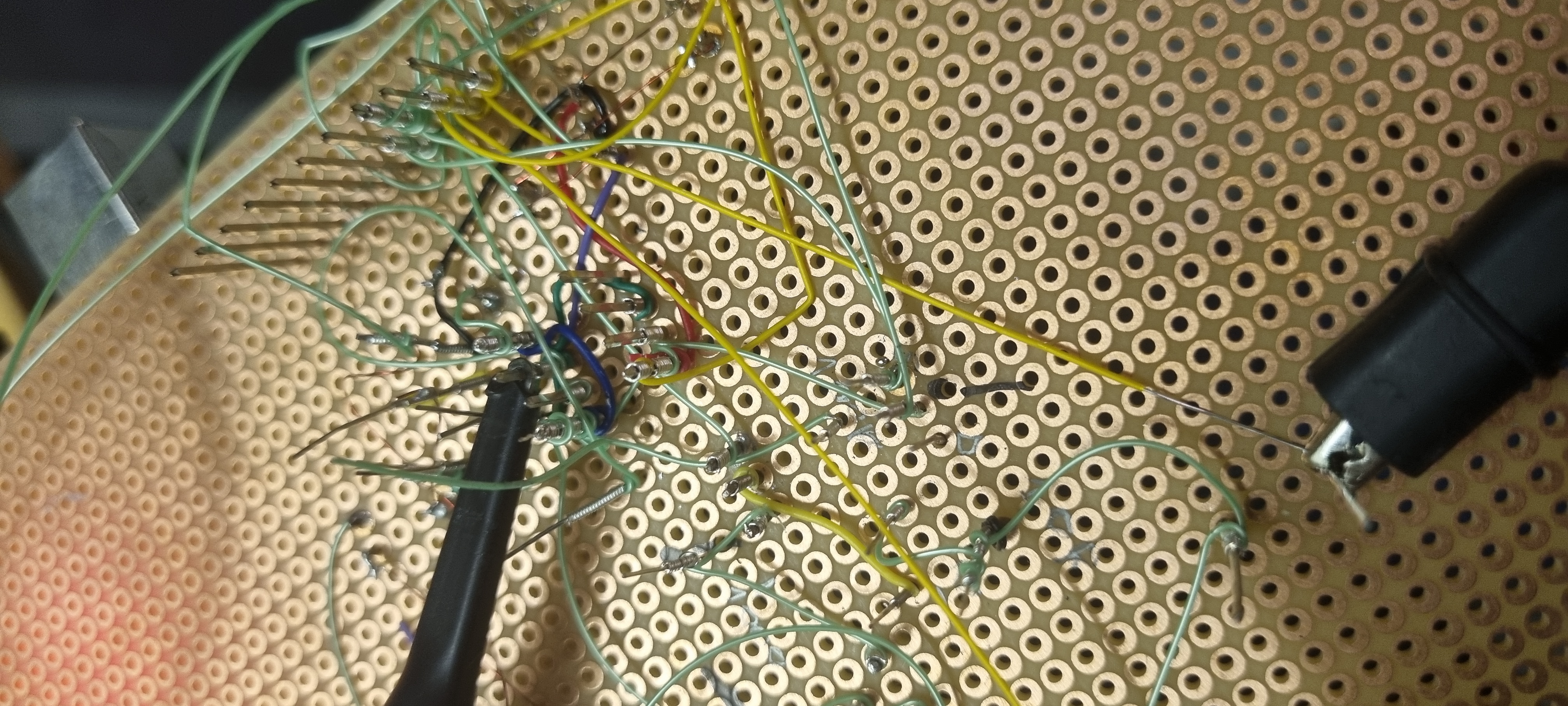
this is my first ever attempt at soldering
how the fuck do i improve
Anonymous
7/26/2025, 3:03:24 PM
No.2934301
>>2934296
more flux
higher heat
chisel tip
Anonymous
7/26/2025, 3:44:52 PM
No.2934306
>>2934311
>>2934296
I would love to see how this happened.
Touch the pad, touch the component lead, add solder. You should be able to get fine joints without extra flux if you're using decent rosin core lead solder. Are you? Does it let out nice smoke?
You should still get some decent flux.
Anonymous
7/26/2025, 4:09:49 PM
No.2934311
>>2934306
>Touch the pad, touch the component lead, add solder
I may have mixed the order of the steps
>decent rosin core lead solder
Yes
Didn't use any flux though
Anonymous
7/26/2025, 5:10:08 PM
No.2934318
>>2934330
>>2934296
the solder goes where the heat is. The bare pads probably never saw any heat. Touch surfaces lightly, there is never a reason to apply force to the iron. Sometimes a bit of flux or solder will help with the initial heat transfer, as the contact between iron and pad may be merely tangential at first.
There is another possibility: The perfboard is very old and oxidized. You'll need more flux to remove oxides. You can try gently cleaning a few pads with scotchbrite or glasfiber brush and then try soldering to see if it is heavily oxidized.
>>2934205
What is the failure mode of ceramic caps? I removed the obviously damaged film, fearing it might short. It's backed up by a MLCC. I did some math and the only explanation for the results is
I am dumb
or
the ceramic cap failed too and is 0F.
Anonymous
7/26/2025, 5:43:47 PM
No.2934330
>>2934335
>>2937212
>>2934318
You can see one potential failure mode of an MLCC right here
>>2933803
Anonymous
7/26/2025, 5:58:14 PM
No.2934335
>>2934330
Guess I'm lucky to have caught it. Maybe failure analysis or naaah? I think it arced over a bit but no biggie.
Anonymous
7/26/2025, 10:22:54 PM
No.2934401
>>2934623
>>2934296
As the other anons say. Additionally, soldering on FR-2 dot-board doesn’t exactly help your chances. The unconnected dots require solder blobs to connect to other pads, while the FR2 is more prone to delamination than FR4. At least consider using conventional FR2 vero/strip-board with a spot-cutter tool, or the breadboard-pattern proto-board with short connecting links designed for DIP ICs.
Anonymous
7/27/2025, 1:15:27 AM
No.2934447
>>2934466
how many dB per decade does a scope loose after it's bandwidth limit? I think I messed something up and started thinking about it afterwards.
Anonymous
7/27/2025, 3:01:56 AM
No.2934466
>>2934467
>>2934591
>>2934447
Do you have an analogue scope?
Anonymous
7/27/2025, 3:10:48 AM
No.2934467
>>2934498
>>2934466
Does it make you feel fancy to add ue to the end of analog? Are you some kind of fancy pants sonofabitch? Did you go to boarding school in Hogwartshire and wear a goofy uniform? I bet you stutter, ya stuttering prick. Your 'mum' is fat and your dad thinks you're gay and a faggot. You seem okay to me though. Fuck you.
Anonymous
7/27/2025, 5:24:30 AM
No.2934498
>>2934504
>>2934467
why don’t you “aks” your mother what the language is called again.
Anonymous
7/27/2025, 5:41:16 AM
No.2934504
>>2934498
So you DID go to boarding school. I knew it, you little faget. I just hopped on the ouija board and my mom said the language is called American English. She then explained the difference by saying that England is a fag country. Then she told me to tell you to stick your anal logue probe up your pee hole, you scone eating rat boiler. I asked her if she really wanted me to tell you that and she said yes.
Anonymous
7/27/2025, 4:08:22 PM
No.2934591
>>2934466
yeah got an anal scope thats 20MHz and the 70MHz one is digital but I'd trust it less when it comes to actual quantifiable measurements. The anal one is just reputable make, high quality. Thats about it.
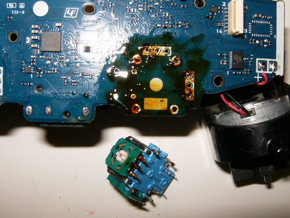
So I got a hot air gun to desolder an analog stick module from a PS4 controller.
It went well, except I completely burnt the plastic on the old stick module as I was removing it.
I didn't really watch any tutorials since it seemed straight froward. What did I do wrong? Not a big deal but curious
Anonymous
7/27/2025, 6:14:43 PM
No.2934606
>>2935053
>>2934605
This video basically shows exactly what happened to me
https://www.youtube.com/shorts/OtNX5Rp5uMg
Anonymous
7/27/2025, 7:12:11 PM
No.2934622
>>2934649
>>2934605
>What did I do wrong?
You applied too much heat
Anonymous
7/27/2025, 7:15:08 PM
No.2934623
>>2934667
>>2934401
Thanks for the tip
I just went with the cheapest option because it's my first little electronics project
Anonymous
7/27/2025, 8:42:27 PM
No.2934649
>>2934605
You did nothing 'wrong' here and
>>2934622
is 'technically right' as in the melting of the plastic results from heat.
But: Electronic components are not designed with reusability or recycling in mind. So it's not like you can always avoid somethibg like this if you want ro achieve your primary goal of removing it. Plastics, high pin count, high thermal mass, heavy power and ground planes on the PCB and modern leadfree solder will often make removal without damage impossible. Most (all?) plastics will simply melt at 300 C and you can't do much about it.
A few things that sometimes help:
Use the ironor soldering gun as much as possible to provide localized heat.
A heatbed can help.
Use flux.
Consider bridging some pins so you can heat them up in unison if you don't have a full set of tips.
If you can spare the time you can work the device up incrementally on several sides.
But generally: Once a device that has plastic, mass, many pins, THT etc. is on a board it will work for that board or go into the trash.
Anonymous
7/27/2025, 8:44:41 PM
No.2934650
>>2934605
Ah fuck. I can't believe you've done this.
Anonymous
7/27/2025, 8:52:52 PM
No.2934653
>>2934605
Curious what that pcb looks like after a proper ipa scrub.
Anonymous
7/27/2025, 9:32:50 PM
No.2934667
>>2934668
>>2934623
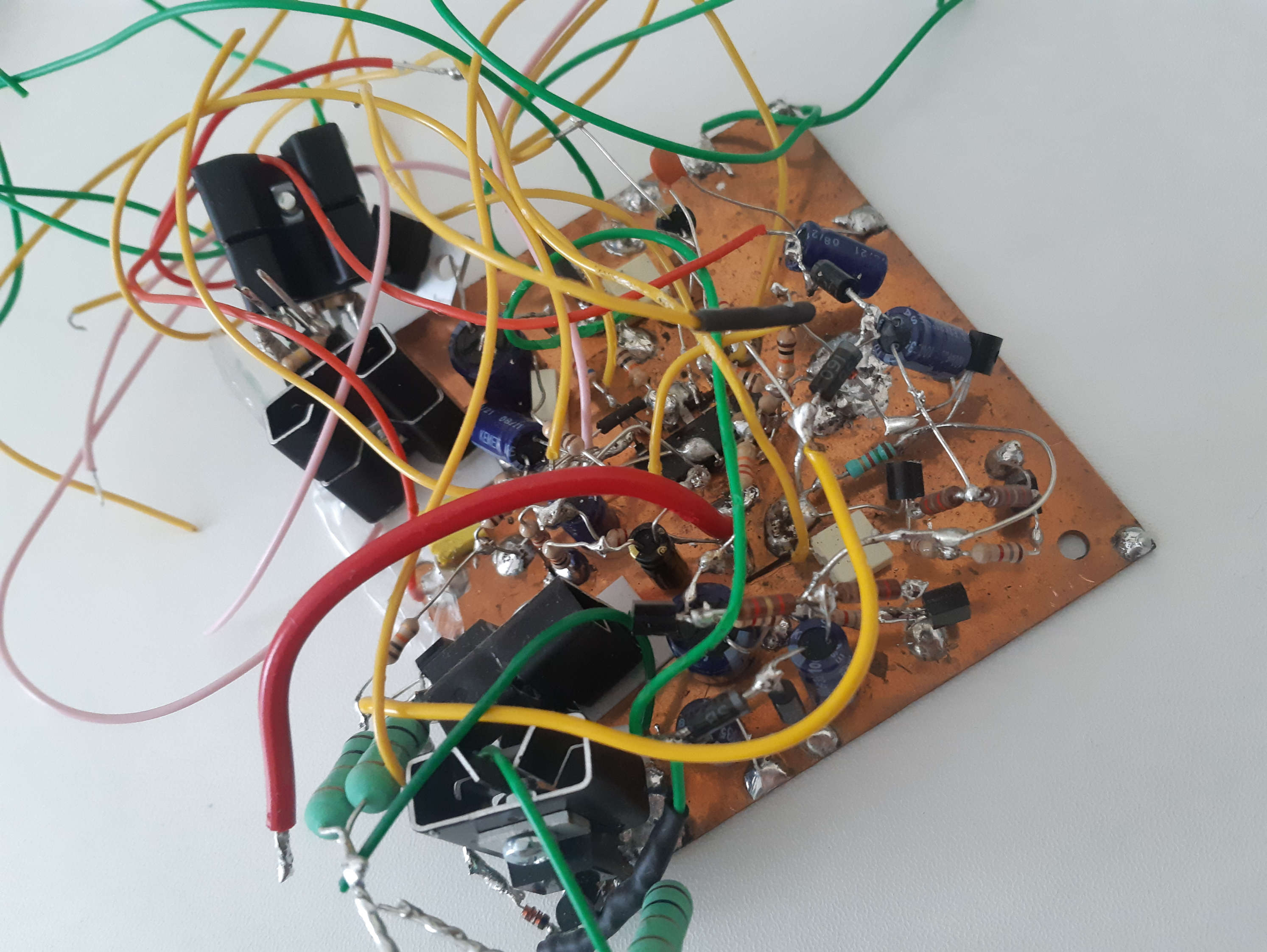
There is cheaper options either. Looknat freeform electronics and rats nest wiring. This is how early appliances were fabricated on an industrial scale. People didn't think of board back then.
Another option is: Get a single or double sided FR4 board. It wont cost much. Scar it with a knife and break over an edge to get the size you need. You can then isolate islands on the surface by removing copper around them. People have made specialized rotary tools for that in the past. But a dremel tool, knife, engraver or whatever you fancy works too. You can then just solder SMD components to those islands, just like you can solder hookup wire and the leads of THT components to them. Sk you end up with roughly as many such islands as your circuit has nodes.
I only learned about the older and more DIY friendly methods after a while in the business and oh boy it does help to have a wider horizon so you don't end up always having SMD components on a PCB for everything, and board to board connectors.
Also look up wire wrapping: It sort of works on round leads too and in doubt you can still solder over it.
https://en.m.wikipedia.org/wiki/Point-to-point_construction
Anonymous
7/27/2025, 9:34:52 PM
No.2934668
>>2934669
>>2934675
>>2934667
Forgot pic.
Look at the islands on
>picrel
Anonymous
7/27/2025, 9:36:08 PM
No.2934669
>>2934668
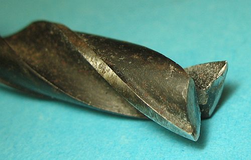
they were formed in a drill press using a wood drill with its center broken off
imo this often still beats perfboard
like I said all of those methods have their time and place really
Anonymous
7/27/2025, 9:47:24 PM
No.2934675
>>2934891
>>2934908
>>2934668
Jesus Christ, how horrifying.
Anonymous
7/28/2025, 12:32:50 AM
No.2934721
>>2934296
Like the first guy said.
Anonymous
7/28/2025, 6:37:03 PM
No.2934866
>>2934296
Bare copper forms oxides, so scrub the shit out of it with scotch brite before soldering
Also use a hotter iron and pre-heat the pads for 1-3 seconds before applying solder
Anonymous
7/28/2025, 8:53:54 PM
No.2934891
>>2934675
Look up Bob Pease's prototypes
Anonymous
7/28/2025, 10:24:29 PM
No.2934908
>>2934915
>>2934921
>>2934675
Look Anon. IDK about you but I get shit done.
Whatever is available now and gets me there fast is game.
Anonymous
7/28/2025, 10:57:06 PM
No.2934913
>>2935033
>>2934167
Guess who's wrong?
Anonymous
7/28/2025, 11:11:51 PM
No.2934915
>>2934908
And I thought my prototypes looked bad
Anonymous
7/28/2025, 11:31:25 PM
No.2934921
>>2935012
>>2934908
>wire-wrap in 2025
Impressive, very nice.
Anonymous
7/29/2025, 5:11:06 AM
No.2934963
>>2935010
Any anons use a fiber laser to create prototype PCBs? Is it a meme?
Anonymous
7/29/2025, 9:16:16 AM
No.2934989
>>2934991
Recently had a power outage caused by a falling tree. When the power was reconnected, power surged on and off wildly. Seemed like a cut in neutral, so i shut off power to the house and got the power company to come back out and reconnect the power properly. Afterward, neither of my garage door openers worked. Pic related is the circuit board for one of them. Can you tell if any of the components are fried? If so, how? Also, is/are there a component(s) in electronics in general that is/are likely to be damaged by surges in power? I appreciate any help with this, electronics have been something I've always wanted to learn more about.
Anonymous
7/29/2025, 9:35:33 AM
No.2934991
>>2935172
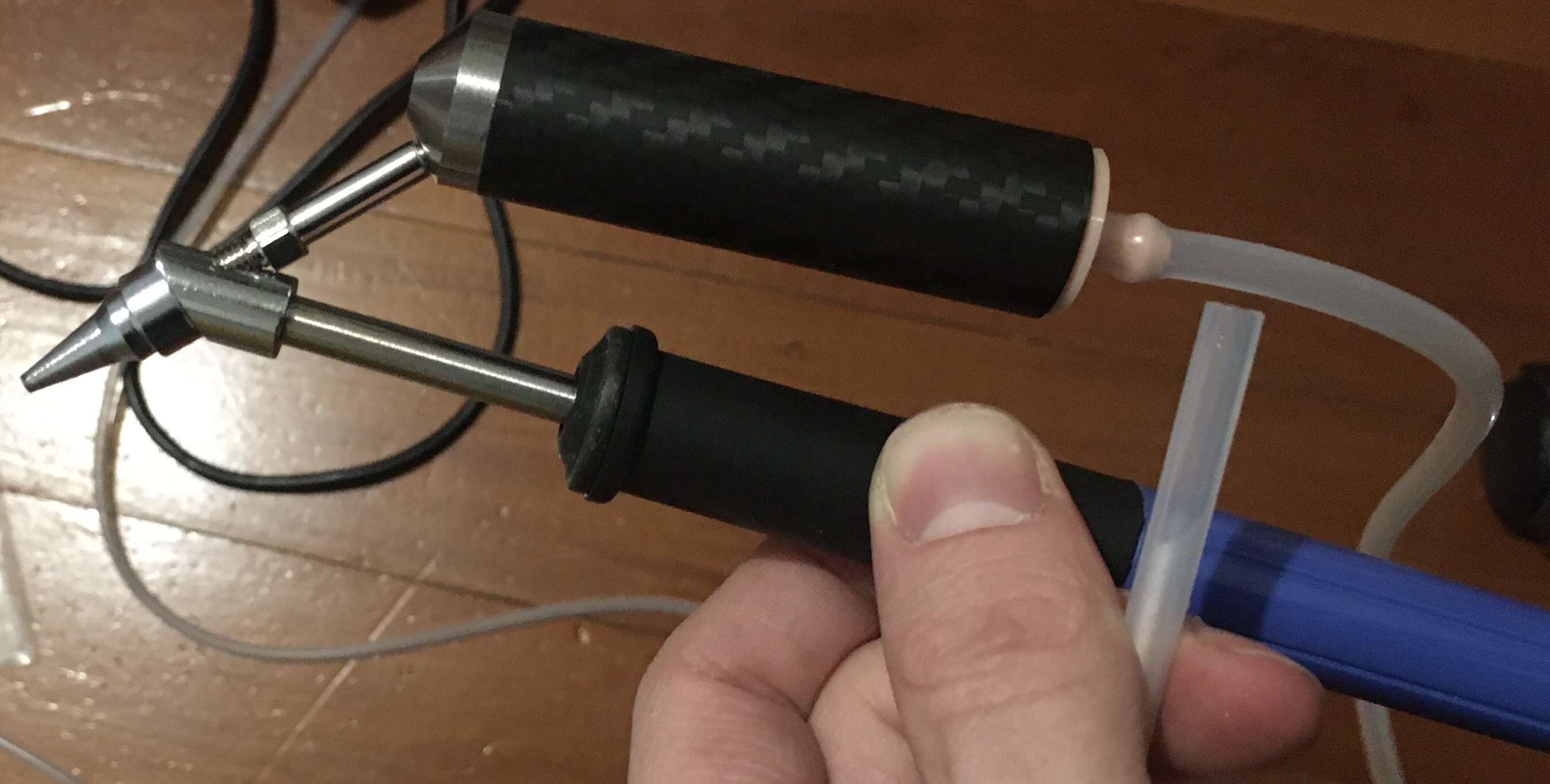
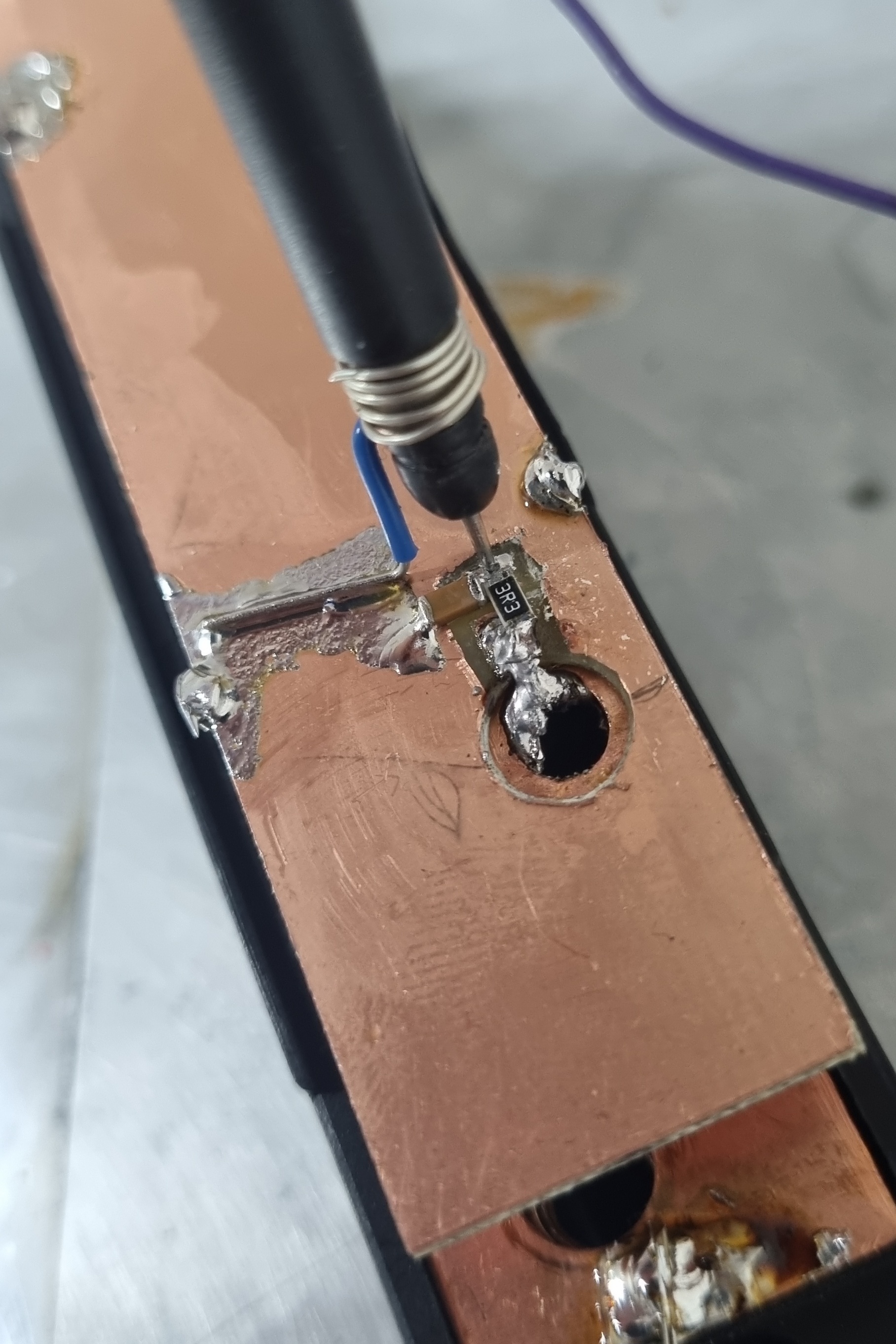
Check out the new desoldering setup. T12 tip, 3D printed TPU hose-barb end-cap, and silicone tube. The other end goes in my mouth, I suck on it. Works ok, but a little DC vacuum pump is probably worth getting. There’s a bunch of fine scrunched up copper wire inside the black cylinder.
>>2934989
The part closest to the power dies most often. That’s often X caps and MOVs, off-line switching ICs, filter caps, as well as the diodes and transistors on the input. If it has an AC transformer that’s probably ok, but surges will go through it to some extent. Fuses are meant to prevent anything else dying in the circuit, so if there are any of them be sure to check if they’ve blown.
I’m guessing the board you posted isn’t the issue, and that the power supply that feeds it is the issue, if anything I’d be a bit suspicious of that 7805 at the top right and the caps surrounding it. R1 D1 likely makes up a zener regulator, which is probably more suspect than the 7805.
Anonymous
7/29/2025, 12:17:48 PM
No.2935008
>>2935010
Is LED filament or EL wire more practical in every situation?
Anonymous
7/29/2025, 12:44:43 PM
No.2935010
>>2934963
No, but the charring of the underlying FR4 and inability to drill holes and edge-cuts makes it still seem significantly worse than a router. I’d sooner recommend using a laser to burn off an etch-resist or to cure a photomask.
>>2935008
EL wire looks better up-close since the light is properly isotropic and not coming from point sources beneath a diffuser, it isn’t as sensitive to damage, and it bends in a more uniform way. On the other hand, it’s a pain to drive, doesn’t age well, has more limited colour selection, is significantly dimmer, is electrically noisy in audio frequencies to drive, and can shock you if you touch a bare end.
They’re both a pain to terminate. These days we’re getting these adhesive COB strip lights, the extra-narrow ones look maybe slightly better than LED filament and are easier to terminate and mount, assuming you don’t want them hanging in mid-air and visible on all sides.
Anonymous
7/29/2025, 1:10:39 PM
No.2935012
>>2934921
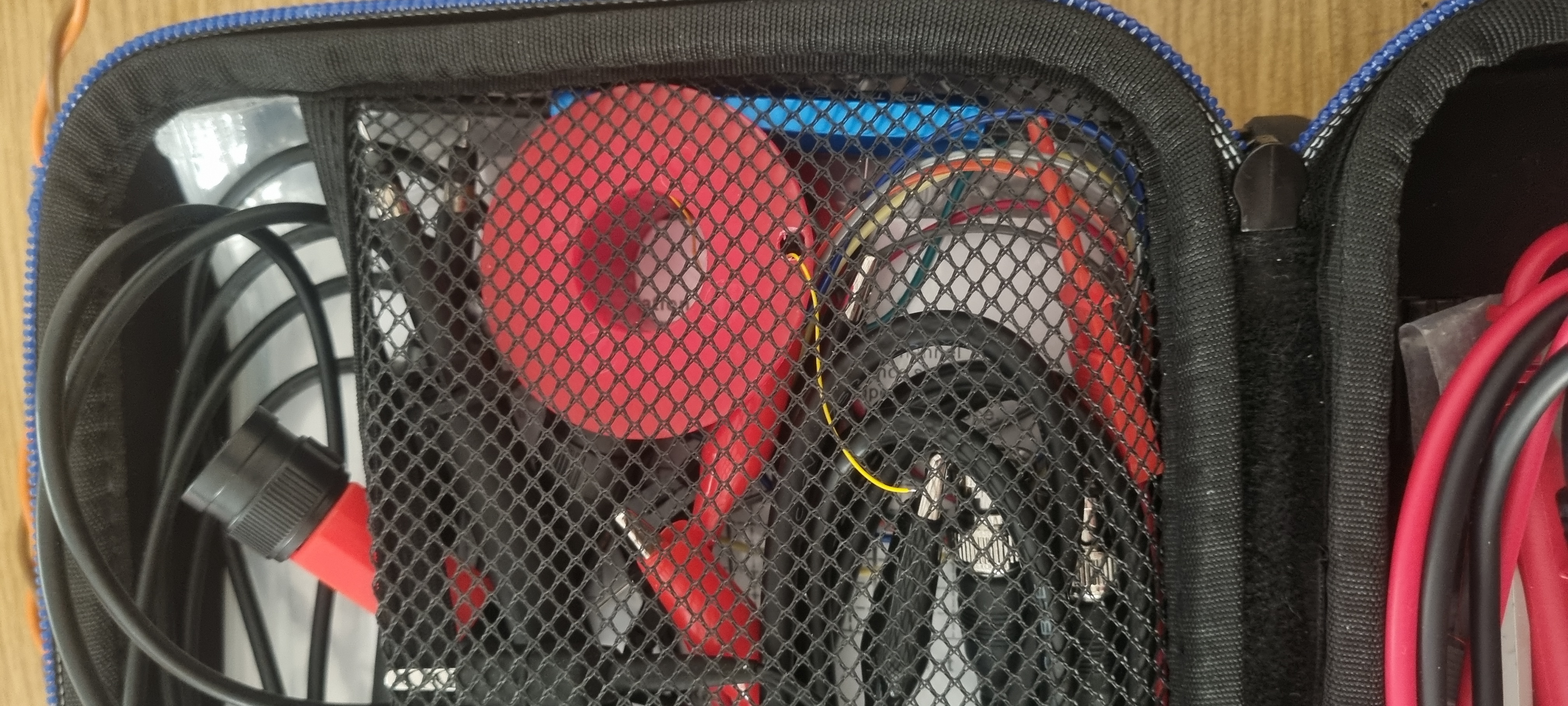
The wire and tool are in the daily kit.
Anonymous
7/29/2025, 2:54:43 PM
No.2935021
>>2935058
>>2935128
*crashes*
Anonymous
7/29/2025, 3:53:29 PM
No.2935033
>>2935038
>>2934913
Guess who's a dishonest RETARD? Hint: it's (You).
Anonymous
7/29/2025, 4:33:15 PM
No.2935038
Anonymous
7/29/2025, 5:27:41 PM
No.2935053
>>2934605
did you apply the shitload of flux? not that there is such a thing as 'too much flux' but you gotta clean after yourself.
>>2934606
bad craftsmanship, probably a woman. you gotta pay attention to how much heat you apply and how it propagates
Anonymous
7/29/2025, 5:38:20 PM
No.2935058
>>2935021
This software teaches just you the importance of regularly saving your work.
Anonymous
7/29/2025, 10:04:11 PM
No.2935122
>>2935128
maybe this belongs on /ham/ but a quick question about metal film resistors: how bad is parasitic inductance and coupling in the 100MHz-500MHz range with them being pretty close and having on the scale of teens to hundreds of mA? will they have a significantly higher impedance? will the coupling be a problem if they are on the same axis with as little as 100 thou spacing from one another?
Anonymous
7/29/2025, 10:54:21 PM
No.2935128
>>2935244
>>2935021
It crashes about as often as any software did 15 years ago.
>>2935122
Just looking at the internal diagrams, THTs and MELFs of carbon film and metal film resistors have a spiral winding, across which I’d assume ESL and EPC. Thin film chip resistors may also have significant EPC, I think thick-film resistors are likely to be best for higher frequencies because of less zig-zagging of the film, but it’s thicker so maybe you get more EPC. Worse thermal noise, if that even matters. Carbon composition resistors, man.
I’d check datasheets, ones by good companies like Vishay should give you ESL values at least, and set up a test jig to measure cross-coupling.
Anonymous
7/30/2025, 2:40:38 AM
No.2935172
>>2935175
>>2935183
>>2934991
Are you a fucking retard?
Don't worry: you soon will be after huffing molten oxides and lead all afternoon.
Come the fuck on.
Anonymous
7/30/2025, 3:01:38 AM
No.2935175
>>2935209
>>2935172
meee meee reee lead n shiet
c'mon now, really? Let me guess: US american? Because you guys are just crazy with that OSHA shit and it seems to even carry over to your private activities.
No one ever died from the average daily exposure to fumes, thinners, fuels, heavy metals, radiation, dusts and what not. At least as long as you're doing some of this and some of that every day.
It might be a different story if youre in the paint booth all day every day. Yeah I can see how you might want ro wear a mask but othet than that? C'mon man.
Anonymous
7/30/2025, 3:22:33 AM
No.2935183
>>2935172
lead fumes are basically a non-issue, it's the flux you have to worry about, and when desoldering i'm not exactly adding fresh solder
Anonymous
7/30/2025, 5:41:16 AM
No.2935209
>>2935238
>>2935175
He built a soldering vape
Anonymous
7/30/2025, 12:20:44 PM
No.2935238
>>2935209
let me guess you go and flip the breaker before workimg on mains?
Anonymous
7/30/2025, 2:08:47 PM
No.2935244
>>2935128
For what it's worth, all of the resistive elements in attenuators I use up to 10 GHz are thin film
Anonymous
7/30/2025, 7:54:27 PM
No.2935292
>>2935293
>>2933537 (OP)
Is this a place to get help with electronics aswell?
Regarding diagnostic of a IC i suspect might be faulty?
Anonymous
7/30/2025, 7:59:33 PM
No.2935293
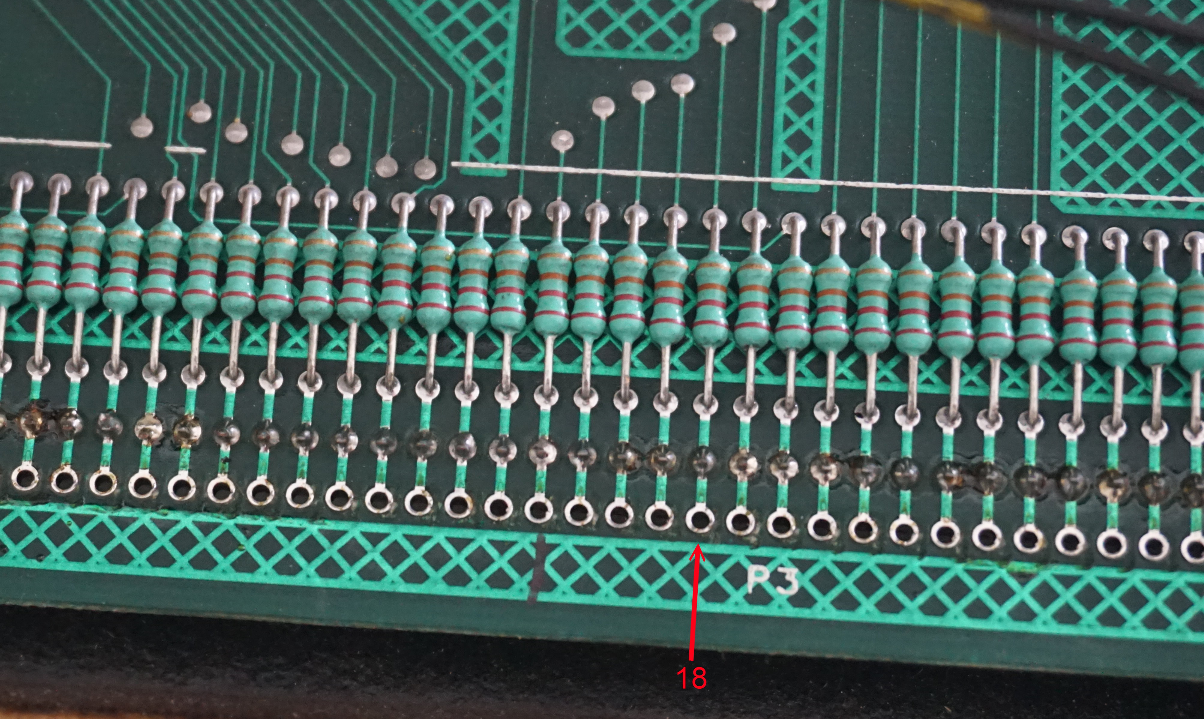
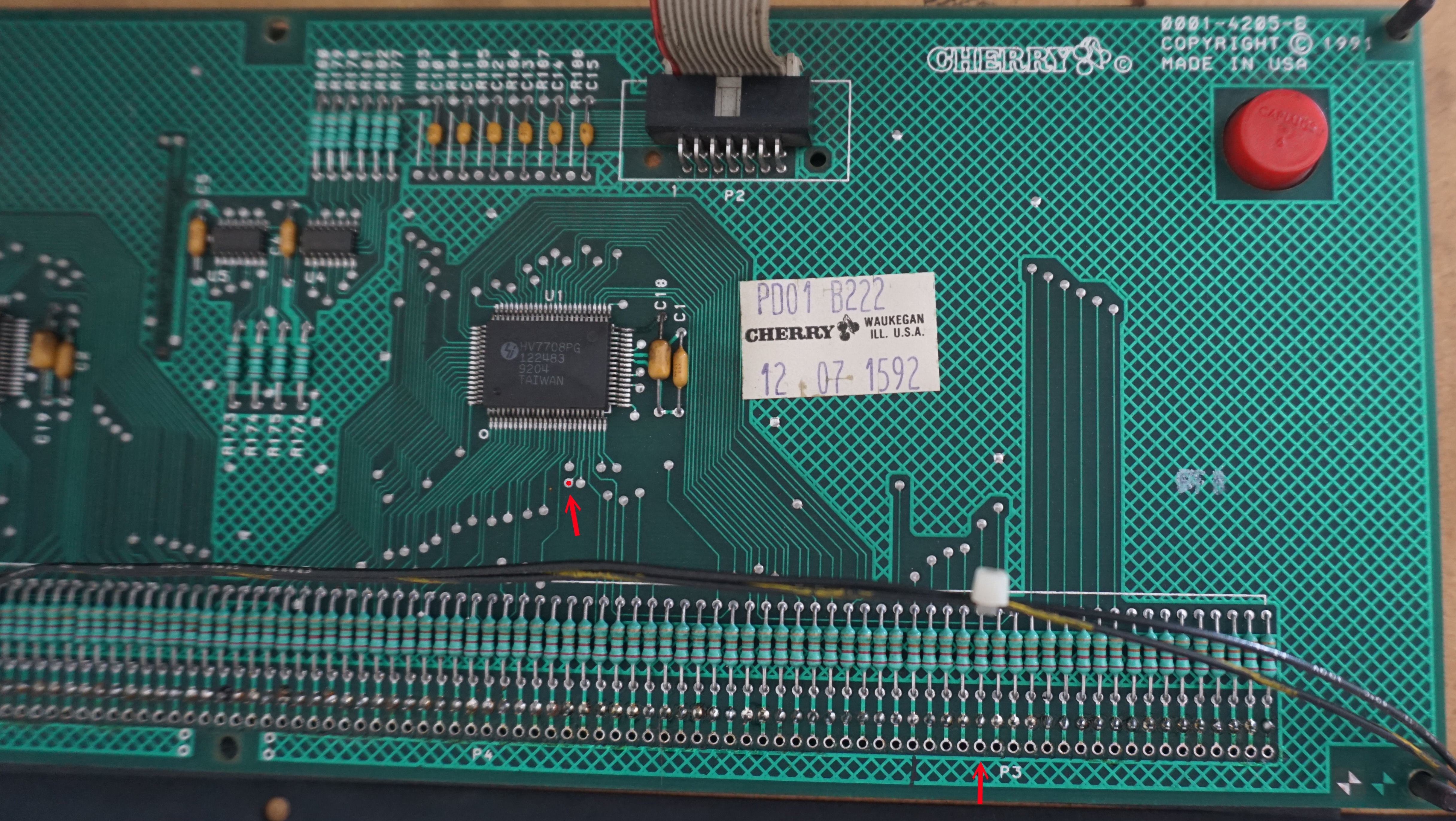
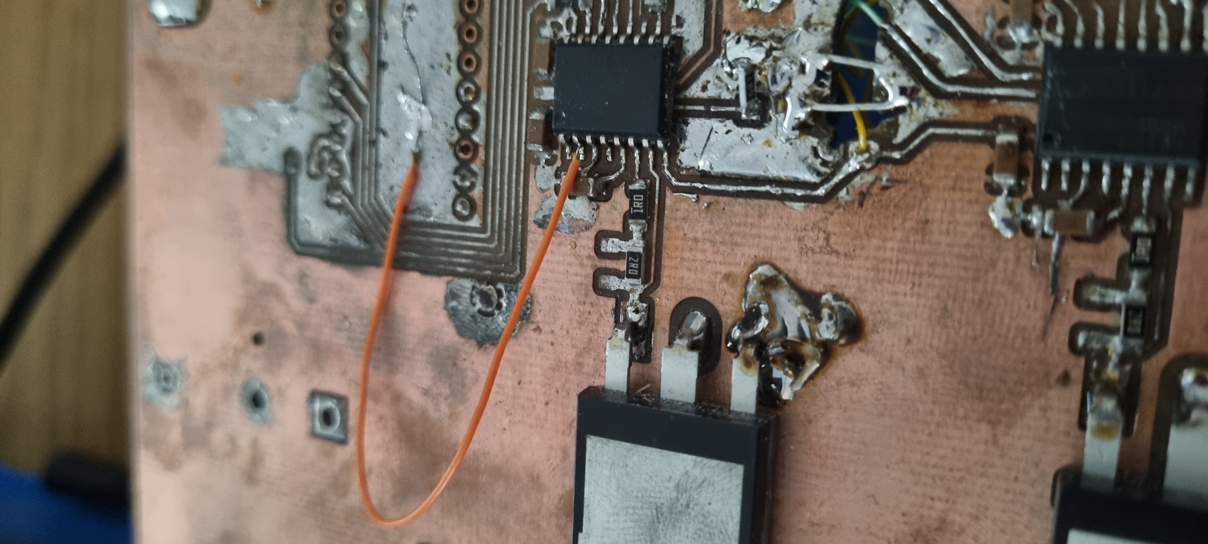
I got an old pinball machine with a dot matrix display. One of the vertical lines is flickering/going out. After asking in a pinball specific forum, others suggested that the IC for that line could be defective. I cant find others with the same specific fault, majority have a line that is not working at all. And there is a fix for that, where you have to drill into the display to attacth a new wire. Anyway, is there a way to figure out if the chip it self is defective? The chip is a HV7708PG, not sure how good it shows in the image on 4chan. I measured from the glass to the chip, and there is a connection all the way. The resistor on the way there measures the same as all the others 21.8K ohm. I looked at just buying a new chip, but its rather scares with places that sells them. And some of the ones that do charges 45€ for the chip + shipping. So i kind of wanna know IF its the chip that is defective.
Only "Solution" i came up with, is to switch the two chips on the board. Since 1 chip only covers 64 pins, and the line has 128, there are 2 of the same chips. Otherwise im kind of clueless what to look for.
Anonymous
7/30/2025, 8:24:13 PM
No.2935300
>>2935307
>>2935298
image was suppose to be this.
Anonymous
7/30/2025, 8:40:53 PM
No.2935303
Anonymous
7/30/2025, 9:05:48 PM
No.2935307
>>2935298
>>2935300
I'm guessing you have a bad connection.Test continuity/resistance from the pin on the display all the way to the chip's pin.
Anonymous
7/30/2025, 9:18:07 PM
No.2935309
>>2935298
Lift one end of the resistor to that pin and reroute one of its neighboring pins. If it still flickers it's the display.
Anonymous
7/30/2025, 9:51:44 PM
No.2935316
Thanks for all of the replies, gonna give it a go one of the following days and update on how it goes.
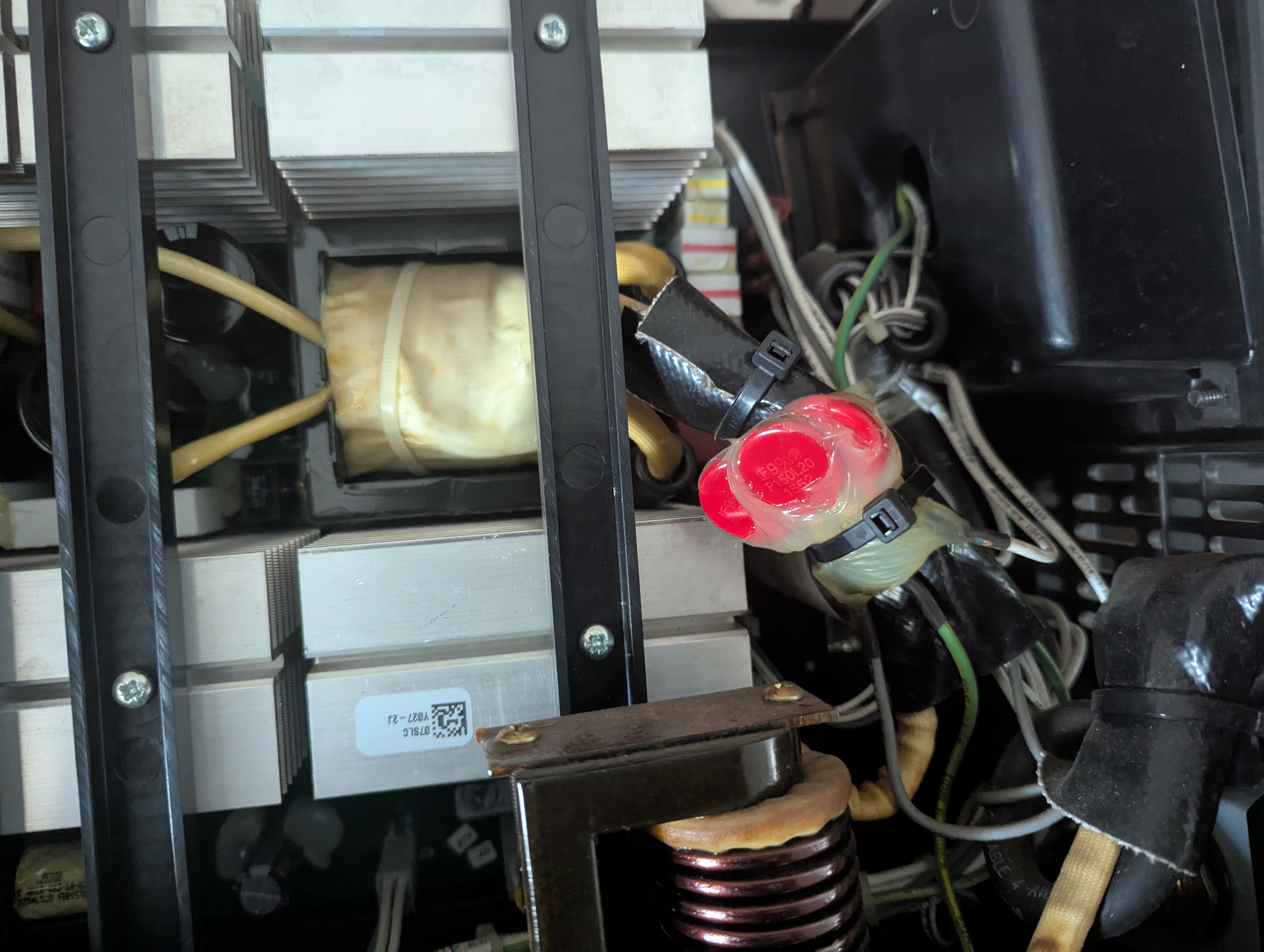
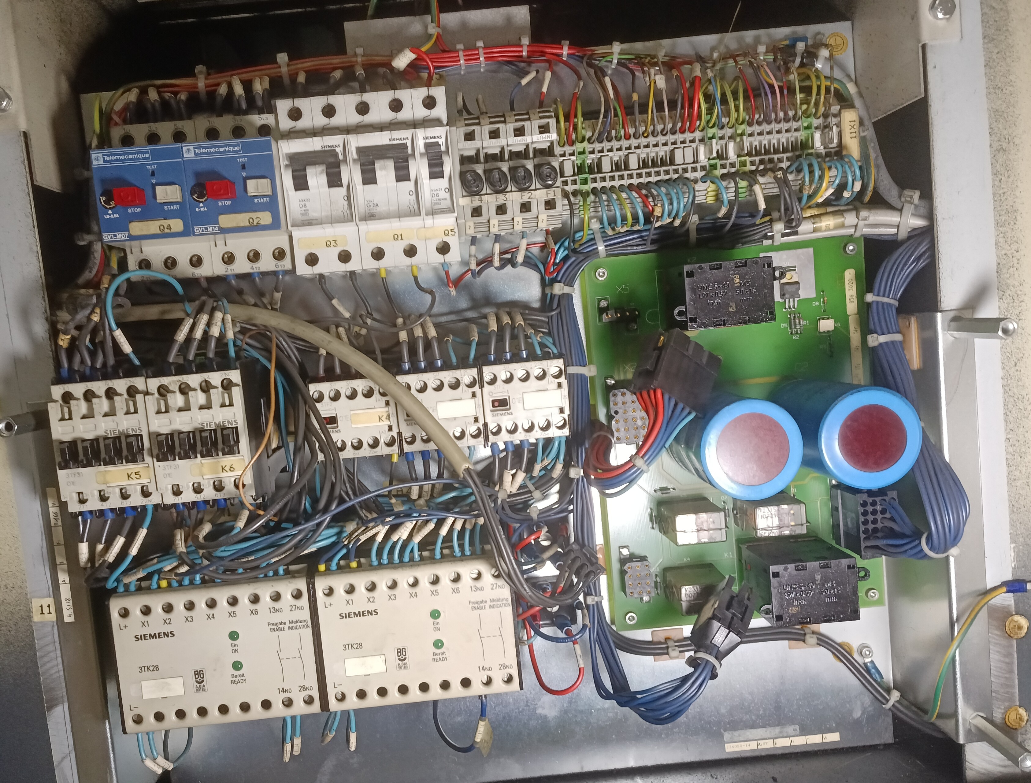
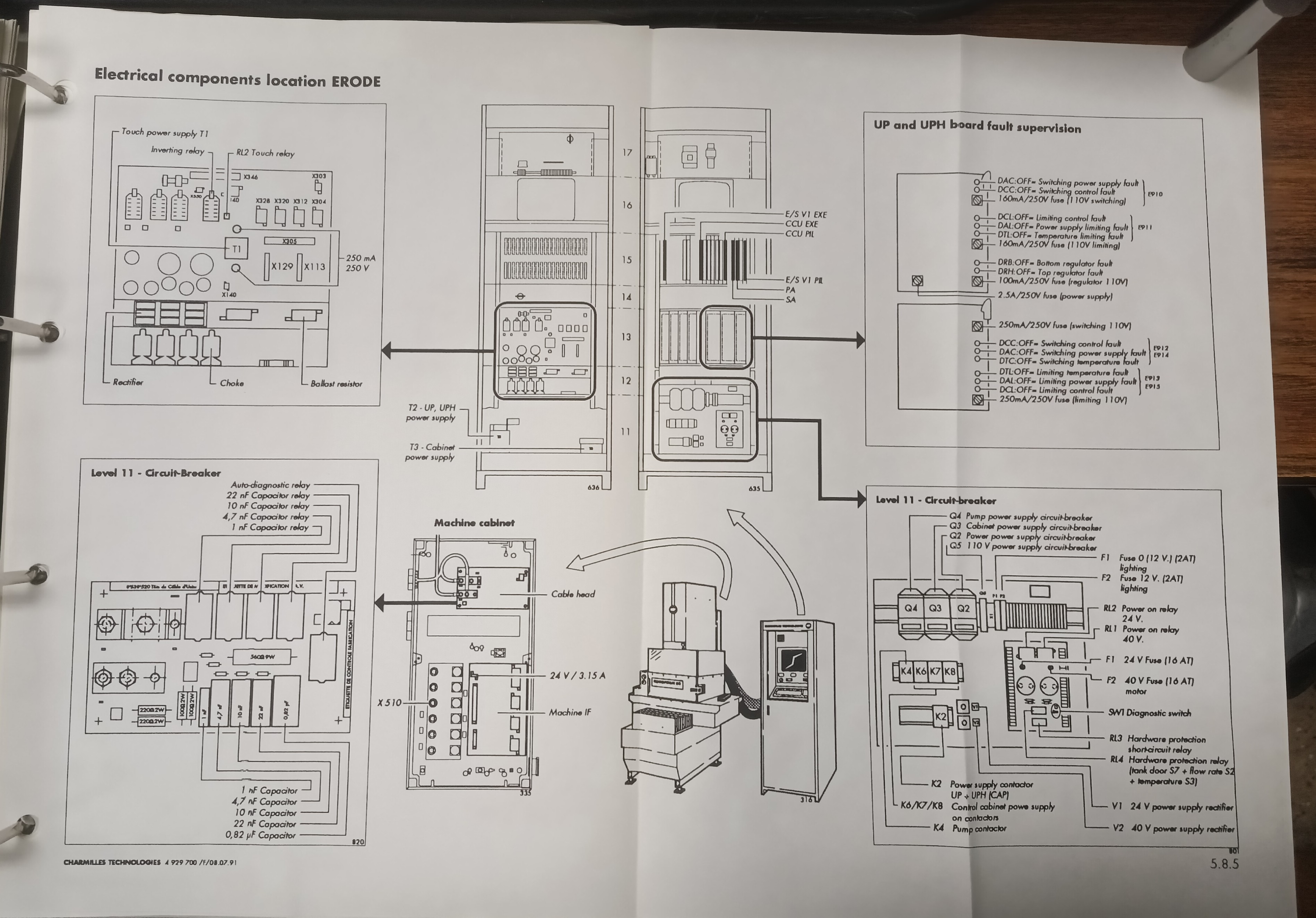
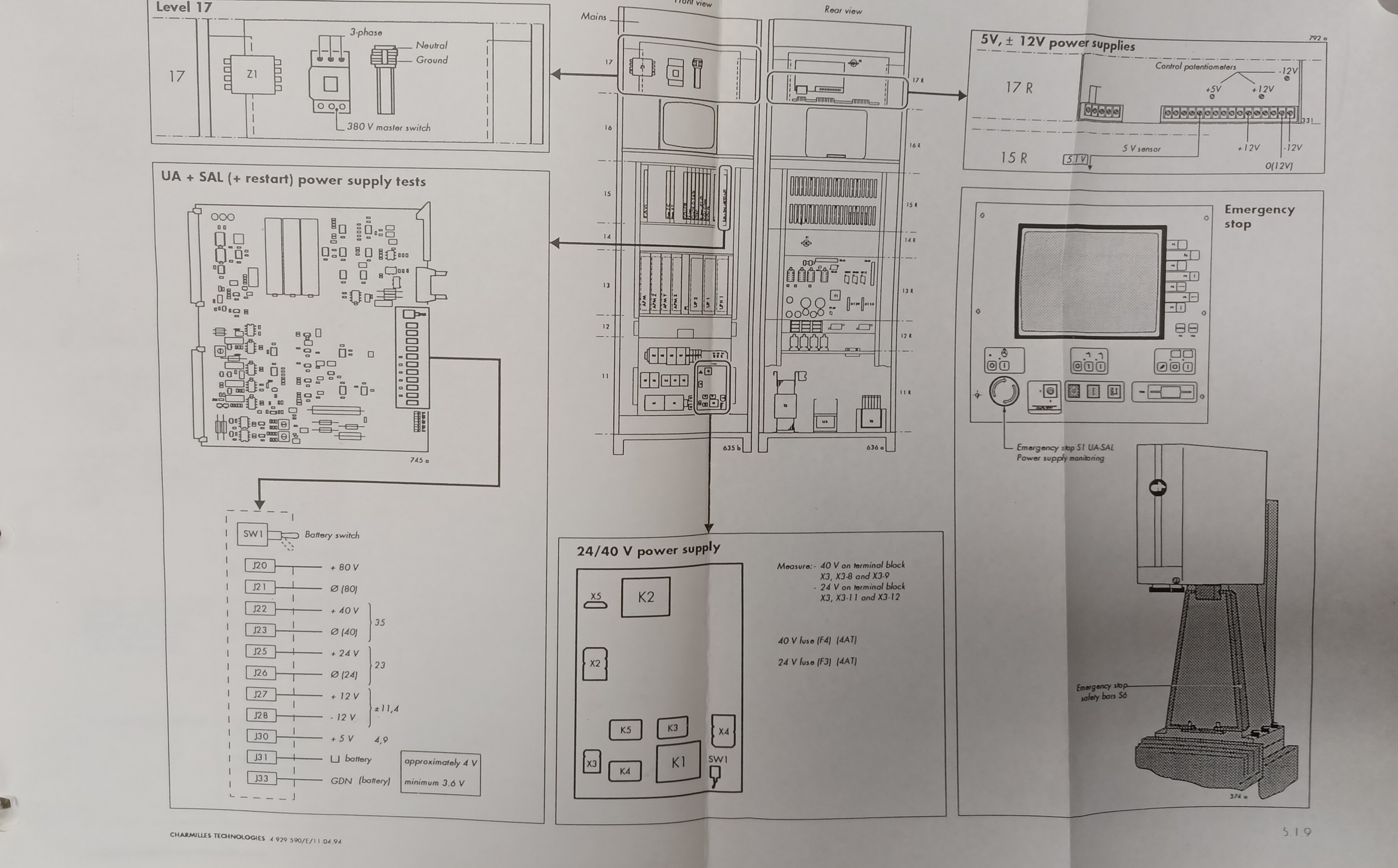
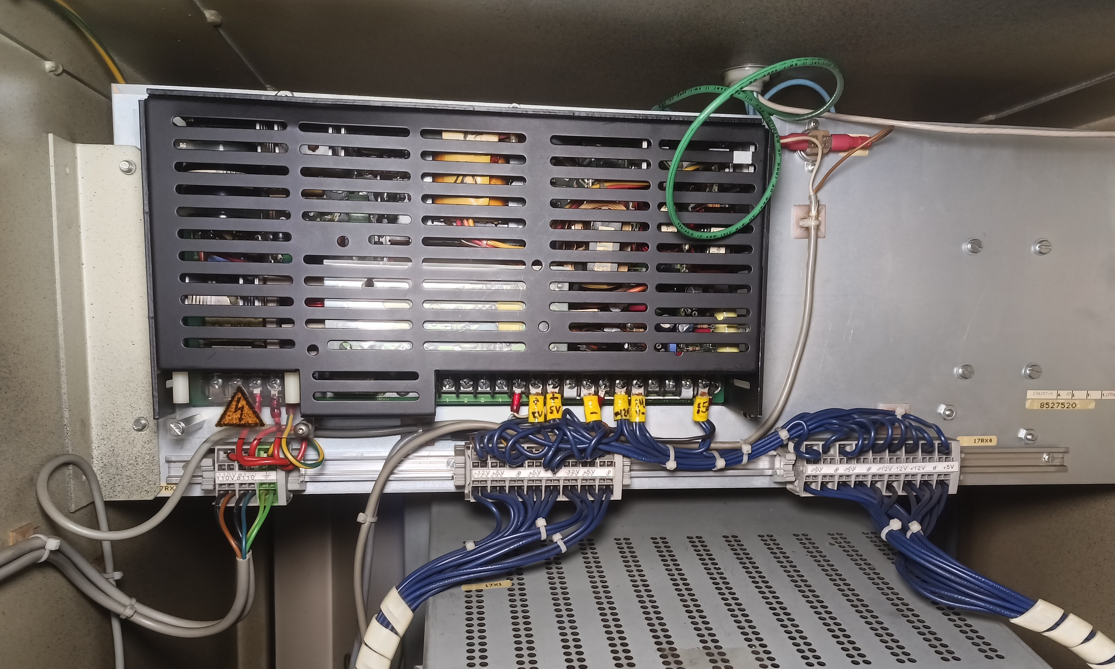
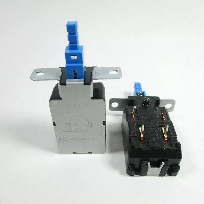
trying to repair a welder, lincoln 210 mp. giving it a look-over before i try plugging it in (bought it as a broken unit.) what's with this varistor arrangement? the 3 varistors are hot glued and zip tied to the positive output. is this just a crude high temperature cutoff?
https://ch-delivery.lincolnelectric.com/api/public/content/a5d73057b1274855aba7d13096462a48?v=c9f3d501 page 28/104
Anonymous
7/30/2025, 10:14:12 PM
No.2935321
>>2935322
>>2935897
Anonymous
7/30/2025, 10:18:15 PM
No.2935322
>>2935325
>>2935547
>>2935320
>>2935321
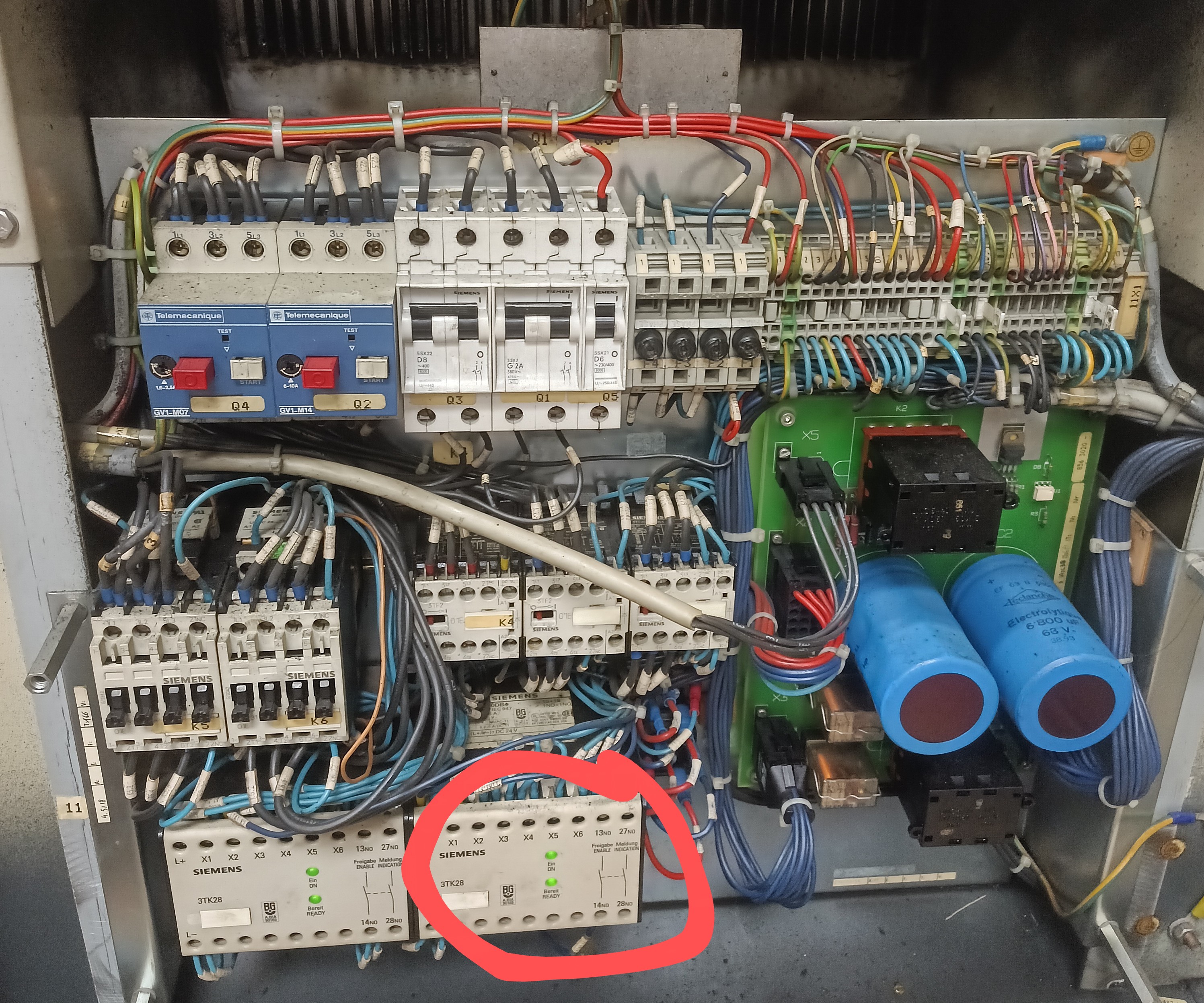
oh wait i thought MOV had thermistor properties as well, which isn't correct. this is for protection against voltage spikes... so what's with the negroe rigged hot glue? bizarre construction.
Anonymous
7/30/2025, 10:27:08 PM
No.2935324
>>2935320
I believe what the jeet who drew that tried to do is a pi
>picrel
pic:
https://files.catbox.moe/ii8yrj.png
(since the 4chin jews blocks random ip ranges to make people buy 4chinplus, i uploaded it to catbox)
Anonymous
7/30/2025, 10:29:03 PM
No.2935325
>>2935329
>>2935322
they could be PTC "fuses", however if they are MOVs I would like to see the person who did they get testicular cancer
Anonymous
7/30/2025, 10:37:42 PM
No.2935328
>>2935371
Sooo I had too much fun playing with a small BLDC before having a good look at its driver. Turns out I let the smoooke out and consequentially found myself unable to ID the driver chip. The driver chip is marked MGM and all other markings are burnt. Its some kind of BGA, maybe 5x5 mm or or so and it takes PWM. I checked online and found a company 'MGM' that is dealing in BLDC drivery but in the kW range.
Does anyone have an idea what part or. product line this could be?
Anonymous
7/30/2025, 10:40:03 PM
No.2935329
>>2935325
they are MOVs, littelfuse P150L20.
Anonymous
7/31/2025, 12:01:08 AM
No.2935346
>>2935371
>>2937075
Any reason NOT to use an 'IGBT Driver' such as 1ED020I12-F2 to drive a MOSFET? I'm looking to use the active miller clamp and just leave desat unconnected.
Is it possible to reshape a rectangular waveform into a triangle using a few passives? Or does one need to at least use an integrator?
Anonymous
7/31/2025, 2:18:46 AM
No.2935365
>>2935381
>>2935364
not a few passives but a few passives and an opamp will make an integrator and as long as you designed it right you shouldn't have any problems with clipping
Anonymous
7/31/2025, 2:19:47 AM
No.2935366
>>2935381
>>2935364
with a few passives and an opamp you can make an integrator
Anonymous
7/31/2025, 3:31:50 AM
No.2935371
>>2935381
>>2935328
I’d look into replacing the ESC board, maybe if you see a matching unit you’ll be able to zoom in on a listing photo to find what IC it’s using.
As for IC searching, use Octopart’s powerful parametric search, as well as checking LCSC in case it’s an “asian brand”.
>>2935346
It’s probably fine. What’s the project?
>>2935364
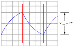
Depends on how triangular you need. A normal RC filter makes a curvy triangular wave, if you use an excessively slow RC time constant it will look more triangular, at the expense of lower output amplitude. Curvy triangle waves are fine for PWM generation. You may be able to use diodes in the RC filter to make it less linear and try to get something more triangular, but I’ve never tried such a thing.
Anonymous
7/31/2025, 4:22:42 AM
No.2935381
>>2935416
>>2935365
>>2935366
Yes I am aware that an OP can make an integrator lol. It's just that OPs have fucking snail pace slew and I was specifically asking about if it's possible without an integrator but only a few passives. Because space, cost etc.
>>2935371
>replace the ESC board
it's potted, not worth the effort, I'm rather curious about the thing. I have a similar, earlier generation, device sadly it's a different chip, some SOIC not a BGA.
>What's the project
The stupid EDM generator that's mostly covered on /3dpg. Rolling with new integrated drivers then. Thanks.
>RC
Yeah naturally I thought of RC first but I was asking because I was thinking maybe there's a neat trick or something, perhaps an L and C arrangement or such. I can't afford to loose much signal. The poibt is to ultimately generate two square signals, that are in sync but have different duty. So it's obvious what I want to do with the triangle. Now if I went with the RC the issue would be that they wouldn't really be centered, but more shifted one way or the other when signals are close to the extreme ends of their duty setting. Not sure how much of an issue that would be.
Anonymous
7/31/2025, 10:57:56 AM
No.2935416
>>2935450
>>2935381
>The stupid EDM generator that's mostly covered on /3dpg. Rolling with new integrated drivers then. Thanks.
Oh. Well I believe you should know that I, the one who told you to that an IGBT driver is probably fine, am also the anon who didn't know what active Miller clamps were until you spurred me to look into them less than a week ago. And also the TPU printing anon.
>that are in sync but have different duty
Instead I'd look into using a monostable circuit or two. The first to set the offset between the input rising edge and the output rising edge if you want that, then the second to set your actual on-time. You could use RC filters followed by schmitt inverter ICs, would be decently fast. Add diodes to make the time delay only on one edge. Though much like anything that uses an RC constant, the time delay would be frequency invariant, which could be an issue if you ever wanted to change frequencies.
Post more details on what possible frequencies, offsets, and duty-cycles you want your circuit to handle.
>third world
>Bought stuff on the internet
>package came with a GPS tracker inside wrapped in sticky plastic
>glowies_Are_watching.mp4
>customer support tells me to throw it away, a literal translation would be a "Logistics Bait" for road pirates
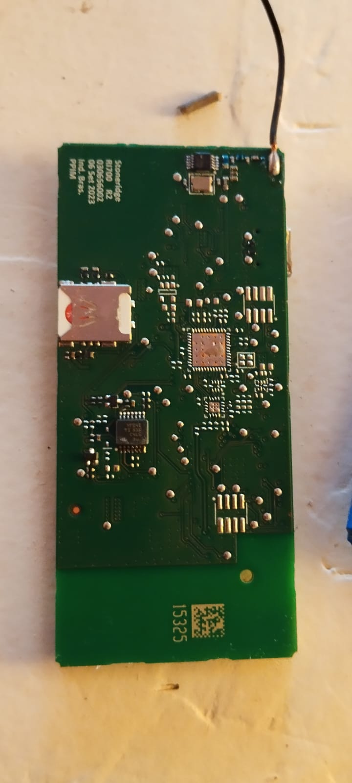
I am an electrical engineer but I never messed with this kind of device. Do any of you know how to access it? There is a sim card on the back so I assume it is through 4G or GSM. The sticky plastic has IDs and PIN numbers but I don't know how to talk to it.
The USB-C light up a led when connected but I think it just charges the battery pack. It wasn't recognized in my linux PC (maybe it needs proprietary drivers)
Anonymous
7/31/2025, 2:22:25 PM
No.2935436
>>2935437
>>2935438
>>2935435
It seems to locally made/assembled (manaus free tariff zone).
Anonymous
7/31/2025, 2:23:39 PM
No.2935437
>>2935438
>>2935436
>>2935435
black wire is an antenna.
Anonymous
7/31/2025, 2:30:37 PM
No.2935438
>>2935439
>>2935443
Anonymous
7/31/2025, 2:43:58 PM
No.2935439
>>2935443
Anonymous
7/31/2025, 3:09:34 PM
No.2935443
>>2935439
>>2935438
had to register for the usb serial drives. They stopped at linux kernel 5.something, I'm on 6.something.
Gonna boot my windows 11 shitbox.
Anonymous
7/31/2025, 4:21:01 PM
No.2935450
>>2935452
>>2935416
So you're saying I start with a square wave from any sort of clock. This feeds into one actually bistable timer. It rises after the input rises and falls after the input falls. Then you somehow & or or the signals to get both outputs? Fot the long signal you need to simply OR, obviously. And the short one AND I believe.
Idk I might try designing that but rn it still looks a fair bit more complex.
I think I have an entirely different solution on hand but I'll have to see I dont like it for I suspect it to be EMI semsitive.
Anonymous
7/31/2025, 4:24:15 PM
No.2935452
>>2935488
>>2935450
Sorry read you wrong, now I see. First mono sets the first blank time and that is used to only trigger the second, which sets the on time and the second blank time is just derived via T1 - Delay1 - T2 = Delay2
I got it.
Anonymous
7/31/2025, 8:42:36 PM
No.2935483
>>2935484
>>2935435
working at company which makes similar concept GPS trackers.
modem is generic Quectel modem, on these devices it typically works as a slave. you can find pinout for it easily and connect to UART thru TCP to sniff AT packets if you really are interested what is happening. USB is used mostly for debugging. communication with MCU is happening thru UART. that is your best bet to get anything from this by listening to AT commands.
Anonymous
7/31/2025, 8:44:52 PM
No.2935484
>>2935483
VCP, sorry, not TCP
Anonymous
7/31/2025, 9:05:56 PM
No.2935488
>>2935496
>>2935452
Both would work. The diodes are kinda sketchy because of the pulsed current into the caps. A CMOS 555 timer or two might be fast enough, and would give you proper latching action.
Anonymous
7/31/2025, 9:14:58 PM
No.2935491
>>2935435
mfw first world never to experience the excitement that comes with having 'road pirates' and the likes
>why live?
Fun device. I guess it hardly does anything but send regular location updates.
>wasn't recognized
what do you mean 'wasn't recognized'? lsusb yields no device, no ID or nothing? IMO this is not a driver thing but can only mean one of two things:
The USB is just used as a means tk power and charge and has no communication connected.
Or the device deviates from USB standard and while it does communicate using the plug the designer again just went with the hardware as its ubiquitous.
Look around the USB if you find a magched pair going to an Ic, maybe an IC that is something like a USB to serial.
In any case pull up the dafasheets for all the larger devices and see how they work. Knowing all the devices and their interfaces usually results in a clear picture about what is going on and where to hop on.
Anonymous
7/31/2025, 9:33:52 PM
No.2935496
>>2935510
>>2935512
>>2935488
Honestly I just hate 555s.
So maybe I should do what presumably you asked and explain a bit:
I am still breadboarding this module. I am currently wotking with a DDS. It gets instructions from uC for the waveform, say TRIANGLE 1MHz. It will then put out that, going from 50mV to 600mV roughly. That goes to an inverting Schmitt made from a LM311, barely fast enough for now. On the other input the same trigger receives a RC filtered PWM from the uC. So you get your triangle and you get to set a voltage with some ripple that splits the range 50mV to 600mV up in 8 bit. Et voila. Add a second trigger and a second PWM channel and that should be what I am looking for.
I have several issues:
I am on a breadboard rn so many issues could partly stem from that.
I just dont like the phase noise. It's okay but ugly. It's probably got a lot to do with residual ripple from PWM.
The thing seems to be able to latch up for some reason. Odd behaviour and it may have to do with the shaky breadboard or the feedback yeeting the Cap on the RC far out of the 600mV range. A latch up would be bad.
The whole thing is stupidly non linear. This would at least mean additional effort programming and I don't like programming. I could put a LUT for calibration on the uC but ugh.
It is also hard to keep the output from bouncing across the whole range. It seems the feedback is either too weak to prevent the bounce or strong enough to latch. An extra buffer for the RC seems overkill. Maybe single diode?
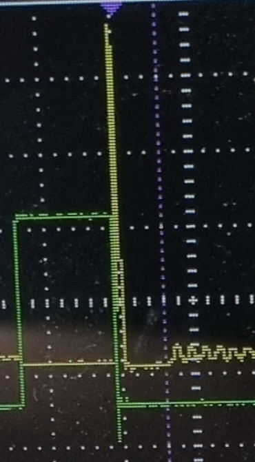
So this got me thinking: The DDS I am using will synthesize sines and triangles at those 600mVpp. It's high impedance and probably not very EMI friendly. It can also put out its scaled clock, bypassing its DAC. In that case you get a full voltage swing. Hence the idea I could perhaps shape the clock signal using passives and avoid the weak DAC entirely.
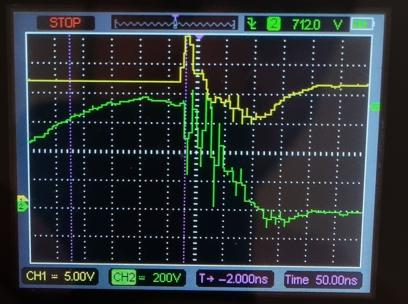
>picrel
is the LM311 out in that arrangement sinking 20mA, 1V and 200nS per div. Might be the breadboard youre seeing mostly. And slow asf 311
Anonymous
7/31/2025, 10:56:19 PM
No.2935510
>>2935520
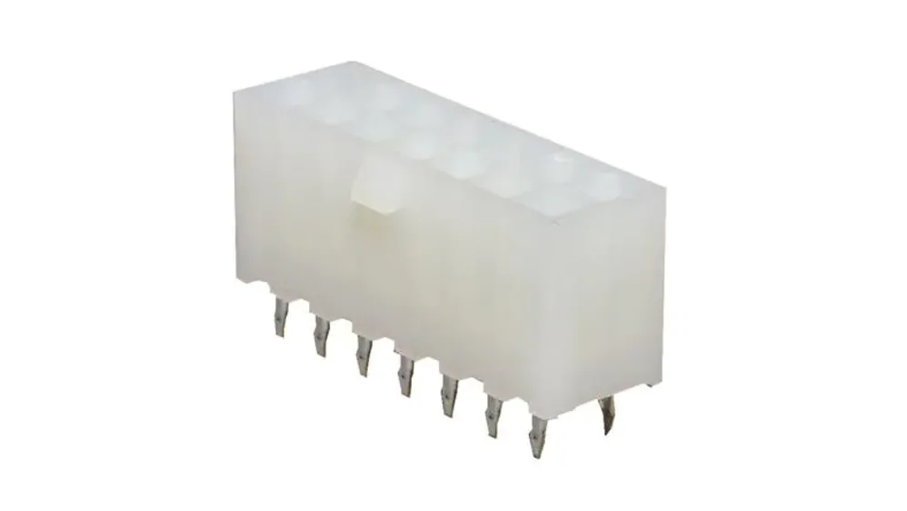
Any recommendations for piggyback/stackable connectors? I can only see single-pole banana plugs and big mains plugs. I want a small 3+ pin connector for use with bus topologies, like CAN and RS485.
>>2935496
1MHz square waves of variable duty-cycle seem like a job for an ESP32, though maybe you have reasons for wanting to go for an analogue control system?
Anonymous
7/31/2025, 11:13:50 PM
No.2935512
>>2935515
>>2935520
>>2935496
post circuit. If you want to just integrate that wave then use an integrator. If you want just a square wave of the same frequency then use it to drive a switch (tranny, comparator, etc).
Use falstad to simulate your ideas, you can share the link here.
A triangle wave can be used for pwm, you just adjust the switch trigger voltage on the up or the downslope.
Anonymous
7/31/2025, 11:17:01 PM
No.2935515
>>2935520
>>2935512
Forgot pic. Stole it from the web.
You are modulating a signal with a triangle control, in your case the reference signal is a straight horizontal line.
>>2935510
I did never trust uCs, not because they are uCs, they're nothing but highly dense digital logic, rather because of my programming.
Also the lab I'm currently working with is a circuit design lab, not CS lab.
1MHz square with variable duty cycle I can in fact get from alot of things, even something like a 328p or 2560. The counters built into those, where are quite capable too and I believe there even was a mode doing exactly what I want: Count up, on compare match tioggle, keep counting to max, when max count down, on compare match toggle again, keep counting to zero then count up again. I could just use two of those counters and difference between the compare register would correlate with my blanking times.
>>2935512
Erm ? Like I said, I am curious wether it is possible to use nothing but a couple passives (aka less space and cost than an OP or anything) to reshape a square wave into a good triangle. Since if this was possible I could just improve an existing submodule without ripping the whole thing up.
Naturally I do understand I can use an integrator if I wantedf to integrate something. And I also understand that a switch of reasonable speed driven by a squareish wave will usually result in a squareish wave of the same frequency.That is sort of redundant.
I will definately not use Falstad to simulate things KEK.
>>2935515
Yes if you want to look at it in that way I am running a modulator. Again that is sort of a redundant observation.
Anyways. KiCAD for some reason started rendering traces in a faggy manner. Is
>picrel
a bug or wtf. I want solid colored traces back.
Anonymous
7/31/2025, 11:51:51 PM
No.2935521
>>2935522
>>2935520
Maybe I'm just delusional and it's always been like that.
Anonymous
7/31/2025, 11:54:04 PM
No.2935522
>>2935521
You gotta press KKK to toggle solid traces.
>4M88D
Anonymous
8/1/2025, 12:43:15 AM
No.2935533
>>2935534
>>2935520
So I did some real quick reading in the 328ps datasheet, because I have 328ps like sand. And the way I read the datasheet:
Two 8 bit comparators of an 8 bit counter compare OCRnA, respectively OCRnB against the same counter, TCNTn. When set to 'phase correct PWM mode' you get the behaviour I mentioned: Count up, then down. So thats my triangle and OCRnA and OCRnB are my reference values.
If I have the space I'll put a footprint and solder jumpers on my board, in case things fail.
Anonymous
8/1/2025, 1:18:18 AM
No.2935534
>>2935520
Well 4 bits of PWM resolution from a 16MHz clock to 1MHz PWM isn’t great. Even with a 20MHz clock that’s only 20 possible duty-cycles.
It’s still an option to find a fast op-amp and comparator, maybe something less than 50 years old.
>>2935533
I think you may also be able to trigger one timer off another timer without using interrupts, but maybe I’m thinking of the newer AVRs and their event system.
Anonymous
8/1/2025, 1:29:30 AM
No.2935535
>>2935538
>>2935520
>Erm ? Like I said, I am curious wether it is possible to use nothing but a couple passives (aka less space and cost than an OP or anything) to reshape a square wave into a good triangle.
depends on what good is. Good enough? Low pass filter. You could easily transform a current-wave into a voltage square or vice-versa with passives, but voltage to voltage? Nah.
Anonymous
8/1/2025, 1:36:50 AM
No.2935537
>>2935550
>no schematic
>cant read IC identifiers because conformal coating
holy shit im going to shoot myself
Anonymous
8/1/2025, 1:39:19 AM
No.2935538
>>2935541
>>2935564
>>2935535
good enough is
>picrel
but screaming fast
and without LGBT inside
which I would have if I either just winged it and went with what I got or had a meams to reshape a square into a good triangle
>>2935538
Sorry, insomnia had me reading thing backwards. I thought you wanted to generate a square from a triangle lmao.
I don't think you can do that passively, at least not in the way you describe.
>pic
is that something you've built or a signal generator?
Think like this, in the frequency domain the square is a sync function right? And the triangle is just two squares convoluted so sync^2. To get back to a sync passively you'd need a square root in the frequency domain, which in the time domain is (????).
Or you just work in the time domain and integrate it.
>and without LGBT inside
why does it matter? Good, cheap passive components probably came waaay before tubes and trannies. People went crazy with heat,moving parts, transformers and motors back in the day.
Anonymous
8/1/2025, 2:14:13 AM
No.2935542
>>2935541
Forgot pic again. But yeah, some variant of pic related, the better the filter the more "straight", but always a little curved, and the more filtered the smaller it'll be.
Anonymous
8/1/2025, 2:48:09 AM
No.2935545
>>2935546
>>2935541
Well yes and no. Anyways.
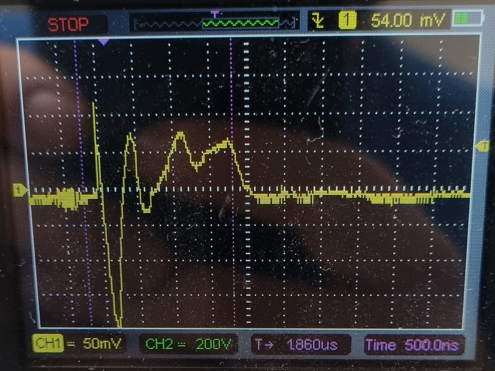
>picrel
is what I'm flying with now because I cant afford to obsess over minor details for more than a few hours. 100nS and 2V per div.
In case you wonder why the match looks so fucked up see next post.
Anonymous
8/1/2025, 2:49:21 AM
No.2935546
>>2935545
It's just 75R coax, hookup wire and
>picrel
is the matching network. KEK
Anonymous
8/1/2025, 2:59:40 AM
No.2935547
>>2935322
>so what's with the negroe rigged hot glue? bizarre construction.
if voltage spike is big enough, MOVs will explode and scatter guts everywhere
this is an attempt at keeping the gory scene G-rated
Anonymous
8/1/2025, 3:15:54 AM
No.2935549
>>2935591
Not sure if this is the right place to post this but, does anyone have any idea where I could find something to replace a 2001 xbox thompson disc drive belt? I see packs of belts on amazon in different sizes, but they're mostly 1mm in width and this belt looks thicker than that.
I've seen people talk about O-rings as a substitute but this belt looks longer than the other drives ive worked on, consolemods wiki says its 55mm folded length.
Anonymous
8/1/2025, 3:19:40 AM
No.2935550
>>2935564
>>2935537
>>2935320
fun fact, each half of the current doubler rectifier is 3 MUR3020WT in parallel. i always read that you never parallel diodes. this welder is rated at 200A peak at 25% duty cycle. i believe this means 33 amps through each diode despite the diode being rated at 30A @ 145C?
Anonymous
8/1/2025, 5:04:47 AM
No.2935564
>>2935567
>>2935538
Does the duty-cycle of both waves need to be variable? The RC Schmitt delay with an OR and AND gets you somewhat of the way there, but it’s not very good if you plan on varying the frequency. A variable frequency triangle wave of constant amplitude, and a pair of comparators, is definitely the most elegant method, assuming you’re cool with using a variable resistor to adjust frequency. Or a digipot, or a vactrol, lmao. If you want digital control over amplitude AND duty-cycle I’d strongly recommend the MCU method. Which also gives you the ability to set asymmetric time offsets if you need them.
Using an RC “triangle” generator won’t be constant amplitude, and the amplitude will vary with current, potentially resulting in a situation where one wave never changes state while the other does.
Is this for transistor gate driving? A discrete Miller clamp perhaps? Or something else?
>>2935550
They’re only conducting half the time, so it’s fine. You even get a tolerance factor for uneven current sharing, though it doesn’t matter much if they’re on the same heat-sink.
Anonymous
8/1/2025, 7:11:17 AM
No.2935567
>>2935564
Yeah it's for gate driving. It's one of those expensive if it goes wrong just once situations. So it needs all kinds of Power_good and Signal_good signals AND-ed together to control the output. Especially during switch on and off.
Active miller clamps I used to do different but I'm forced to use integrated drivers now and the ones I am getting soon have DESAT and CLAMP builtin. I hope DESAT can just be tied to GND and the IC happy with that (I didnt read the docs). So with the clamp built in I need it for switching a transient generated by unclamped inductive switching. So one switch only ever switches when it sees no current and no voltage and as such will only ever see current and whatever it's RDS_ON produces. The other one does the hard work. Get it wrong and the switch selected for current capacity and not voltage gets to see spicy electrons.
Anonymous
8/1/2025, 12:30:40 PM
No.2935591
>>2935750
>>2935549
Honestly have you tried aliexpress or alibaba?
Anonymous
8/1/2025, 3:29:57 PM
No.2935611
>>>/g/106110469
Need help figuring out the ins and outs of this. Is there any possibility of me getting a good enough read for amplitude/voltage output? Or should I just try and find different probes for my multimeter and pray it works?
Anonymous
8/2/2025, 3:31:09 AM
No.2935703
>>2935915
>>2935694
It’s a transmitter? Is the frequency higher than the scope bandwidth? If not then it should be feasible. The scope may have a spectral power analysis method that will work for you, if not there should at least be a way to export a waveform and process it on a computer. A dummy load in place of your antenna is a good idea for testing to ensure the radio transmits right, but if you’re trying to test the entire system without individually using an antenna analyser, VNA, or SWR meter, you’ll need to measure voltage and current at the same time. If your scope has a math function, you might be able to multiply voltage and current live, and compare that to what V^2/R would be for your impedance or what you measure across your dummy load. Otherwise that should still be doable on a computer with exported data.
If the bandwidth is too small for the frequency you want to measure, maybe it’s doable with downconverters, but it would be an uphill battle.
Anonymous
8/2/2025, 3:39:05 AM
No.2935708
>>2935772
>>2935915
>>2935694
>need help
you sure do
a scope is a super duper tool to measure voltage, frequency, shape of waveform, distortion, duty cycle etc etc etc
FFT is a special feature to show off the spectrum of frequencies found in the signal
it makes no sense to use the FFT function for anything other than that
what you need are video tutorials to show you how to do what you want
luckily youtube has over 9000 such videos
as
Anonymous
8/2/2025, 6:10:41 AM
No.2935750
>>2935846
>>2935591
https://www.ebay.com/itm/184720173135
Found one for specifically thompson drives. Everywhere else I looked had smaller bands for the other dives. Never tried those sites cause I heard parts from there are bad quality.
Anonymous
8/2/2025, 6:37:42 AM
No.2935760
>>2935772
>>2935915
>>2935694
>>2935694
>>2935694
I dont think you need FT or FFT to figure put voltage, or the amplitude, which sort of is the same as your voltage at peak. Or any of that. Perhaps just admit you are clueless and need help, explain what you need and people will help. No point in snatching up some big words in an effort to feign expertise, that sort of goes against your objective: Getting help.
>None of my probes are precise enough.
What exactly do you mean?
Show your probes. Explain what you want to measure. Also explain what you expect to see and what you see instead.I am not sure wether you are qualified to make the assesment that your probes are not 'precise enough'. Is it their bandwidth? Or do you need a 1:1? Or something else?
When you measure off of a BNC:
Make sure your ground lead is short. That means expose the probe, wrap a wire around the shield connection and let that stick out. When measuring touch the probe to the BNCs inner conductor and at the same time touch the shield wire to the BNCs shield. Depending on your source impedance you might want an appropiate termination. You can just add one. Some scopes have a selectable 50R termination, in that case of course use 50R coax. Most probes cable is high insertion.
>Should I try finding different probes for my multimeter
RF isn't exactly multimeter territory. But you can do stuff like rectify and smooth or proper peak detector and measure using your multimeter. Perhaps build an OP based amplifier. If you calculate the error you'll probably find your measurement is shit and you might aswell just buy an appropiate scope at this point. But the error will be small enough to allow you to validate if it's operational.
FNIRSI DSO-152 seems to be 25 bucks online. Such a thing is bottom of the barrell but it might be enough and is also good for someone wanting to learn without fear of nuking 10k bucks.
There also this open source DIY kit 'DSO-138' I think you can have that way cheaper even.
Anonymous
8/2/2025, 8:48:58 AM
No.2935772
>>2935782
>>2935708
>>2935760
Maybe he specifically wants to see what output signal is in-band? There might be harmonics that he doesn't care about, or that are getting bounced back from the antenna. Still I think that's a task for a filter, be it on the probe or between the radio and antenna.
Anonymous
8/2/2025, 10:44:55 AM
No.2935782
>>2935800
>>2935772
Whatever it is bro must exain what he wants and expects to see in terms bro is familiar with. And also explain what it is he has. Like not even sure if bro got a scope or only a multimeter and hopes to get test leads that make his multimeter RF compatible?
What would work to galvanically isolate UART at 115200 baud and 5V, isolation of at least 1500V or higher?
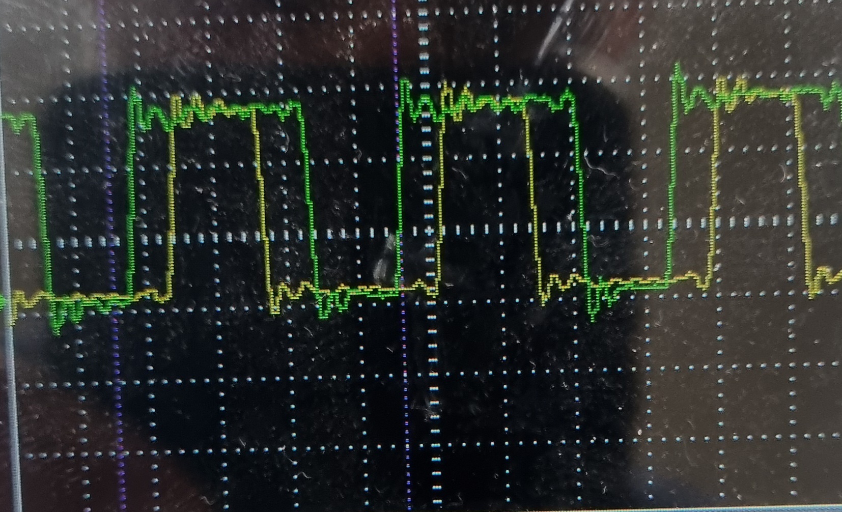
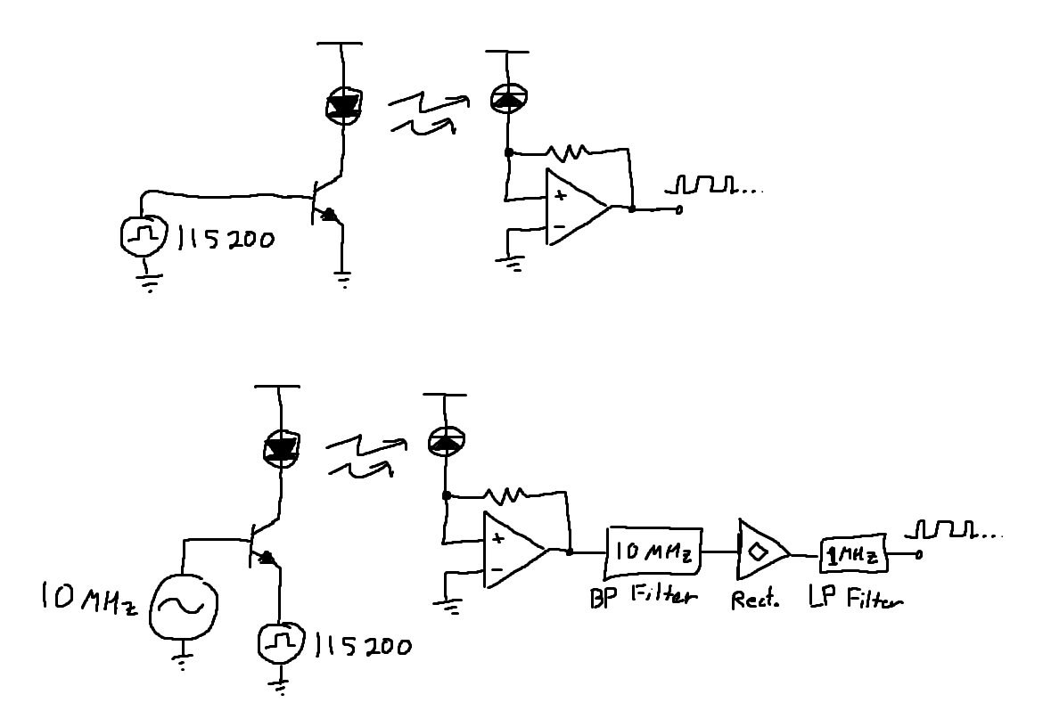
Is it worth to DIY or get an ASIC instead?
Anonymous
8/2/2025, 1:09:26 PM
No.2935800
>>2935782
see the /g/ thread he linked to, he has a scope
>>2935789
High speed optoisolator. The Renesas PS9123 would work but there are many out there that will do the job. I wouldn't bother trying to diy an optoisolator with an LED and photodiode as it would probably not work for 115200 baud. The only practical diy option that comes to mind is to wind a pulse transformer but I'd just use buy an optoisolator they're dirt cheap
Anonymous
8/2/2025, 7:57:44 PM
No.2935835
>>2935844
>>2935861
>>2935789
like the other anon, my immediate thought would be to optically couple the circuits. but i disagree that you couldnt diy it; theres plenty of cheap photodiodes that operate just fine into MHz. you can even add an oscillator and some filters and now you have hillbilly radio.
but an optocoupler would be much simpler and do exactly what you want.
Anonymous
8/2/2025, 9:36:06 PM
No.2935844
>>2935835
Optoisolators are so cheap that I see no vantage in diy one for 1.5 kV. Most "home" electrical stuff go up to 700 V before braking down.
Would be fun to try to acoustically/mechanically isolate it in a diy way heh.
Anonymous
8/2/2025, 9:48:26 PM
No.2935846
>>2935750
> Never tried those sites cause I heard parts from there are bad quality.
Everything comes from the same factory in the glorious republic of china. Doesn't matter if it is from ebay or "made in the USA".
Anonymous
8/2/2025, 11:31:57 PM
No.2935860
>>2935789
If you have or can get an old phone that plugs into the wall, that usually has very good isolation and protection. Some even have additional gas discharge tubes.
Old modems, fax machines, would have similar or better protections.
Power bars sometimes have telephone jacks that are protected as as well, if you’re not using them you could probably just lift them out of your power bar and use them for something else. Might just be MOVs, however.
Anonymous
8/2/2025, 11:33:44 PM
No.2935861
>>2935862
>>2935835
> 10 MHz
Why the “carrier” frequency and inject the signal?
Anonymous
8/2/2025, 11:36:02 PM
No.2935862
>>2935861
decreases noise, increases SNR.
Anonymous
8/2/2025, 11:41:55 PM
No.2935864
>>2936700
>>2935789
I use a USB isolator and a USB to serial convertor, cost like $30.
Anonymous
8/3/2025, 1:15:12 AM
No.2935897
>>2935899
>>2935320
>>2935321
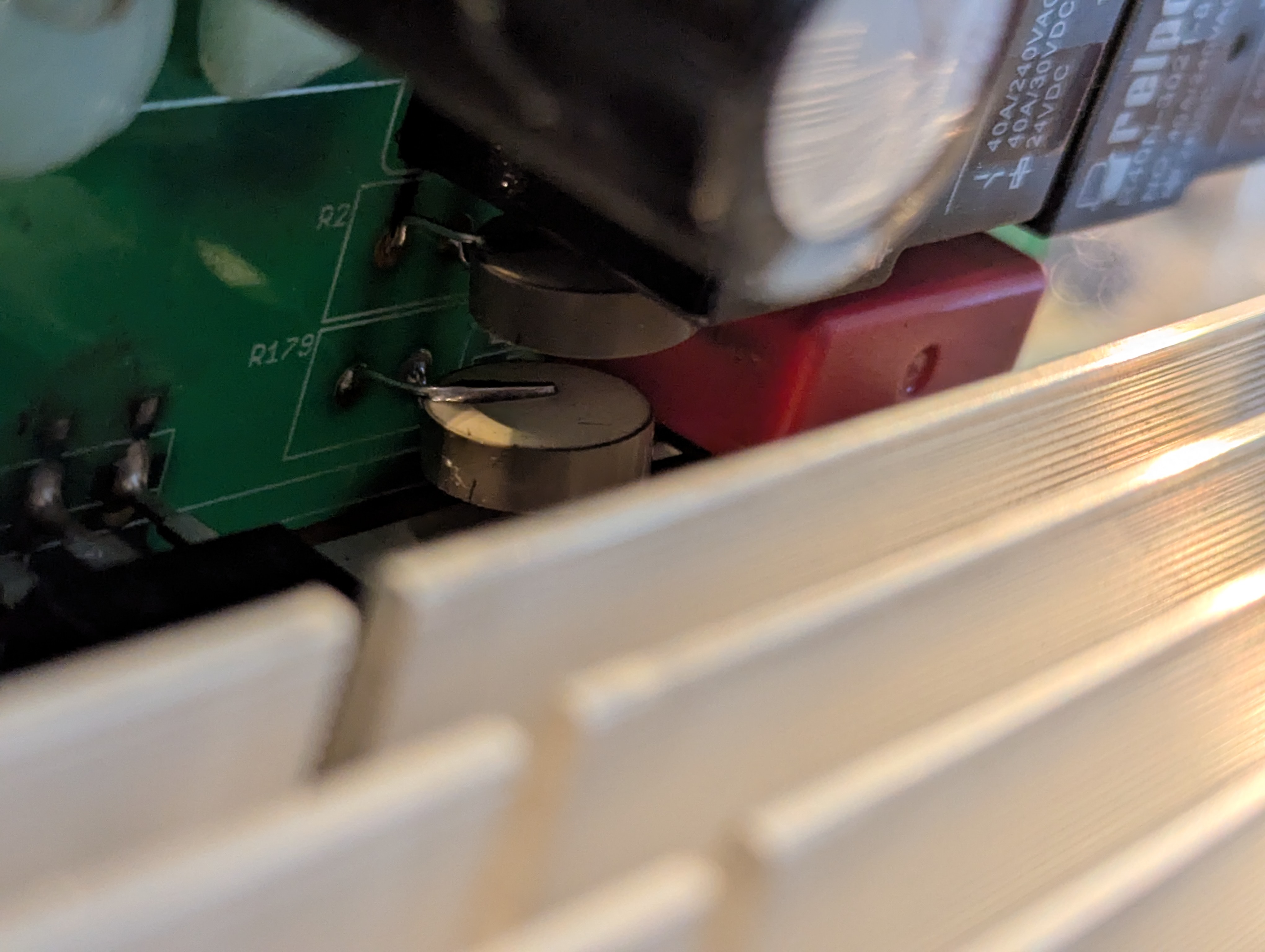
the more i study this thing the more bizarre it gets. the front panel display/MCU has its own switching supply. but it's not coming directly from the 120/240 mains input because the input capacitors on the display/MCU board are two 50V rated capacitors in series. i can trace it upstream to the source of a 100V rated NFET but i can't figure out where the drain goes to.
would be interesting to see a schematic but there's no chance of that ever happening.
Anonymous
8/3/2025, 1:21:54 AM
No.2935899
>>2935908
>>2935897
It’s possible they are just “siphoning” power from somewhere randomly.
The best example I saw of this is in a microwave oven… the 120V shaded-pole cooling fan simply had some extra turns of enamelled wire around the open coil to provide low voltage for something.
Brilliant, I thought.
Anonymous
8/3/2025, 2:01:39 AM
No.2935908
>>2935899
https://www.onsemi.com/download/data-sheet/pdf/df10s-d.pdf
the MCU board has the above smd rectifier in front of the TNY switcher so i'm assuming it's fed from an AC source. the only source of an AC tap i'm seeing is the HF transformer that powers all of the low voltage DC circuitry. would it be able to rectify (just guessing) a 50 khz or whatever AC signal considering they're "normally" meant for 50-60 hz mains?
>>2935703
Bandwidth of this scope is 500MHz which covers the entire range of the transceiver I am attempting to test on the right side of the image. I could export to a computer using the floppy. The exact parameters I need, such as DC coupling, 50 Ohm in, etc. are things I just have no clue how to set them on this particular model.
>>2935708
I am looking to display, all at once, to someone who has an arguably poorer understanding of these concepts than me, the exact spectrum of frequencies (baseband, sidebands, etc.) as well as voltage, amplitude, and possibly wattage as result of a function in one window so I can take a picture and send it to him overseas for his understanding that this radio does infact function properly.
>>2935760
You are correct, sir. I am a novice and I'm not well versed in theory, but I should have been more specific. When I referred to probes, I was referring to multimeter probes. I have a fluke hanging up just out of frame, and the probes aren't skinny enough to be stuck crudely into a BNCf connector's contact to measure output voltage/amperage. I don't want to open the radio and measure directly from the transmission line, and there are no schematics or clues online about this particular unit to aid me in doing so safely. It's a pretty rare transciever and the pricepoint is well above $10,000.
Anyhow everything is moot now, I ran out of charge and the battery connectors are absolutely unobtainable. I have to wait for word from the supposed OEM on a quote for a charger. I don't have an adequate power supply to produce the current/voltage required to charge the battery using wire or alligator clips.
Thanks for your time and input so far.
Anonymous
8/3/2025, 3:42:57 AM
No.2935925
>>2935929
I'm considering setting up LAN and coax through my house, and would need to build a wiring cabinet for the switches and router and the like. how do I run power to it?
Anonymous
8/3/2025, 3:48:10 AM
No.2935929
>>2935934
Anonymous
8/3/2025, 4:19:37 AM
No.2935934
>>2935929
I'd rather not have a slapdash fire hazard. if I'm gonna do it, I'll do it right.
Anonymous
8/3/2025, 6:37:06 AM
No.2935945
>>2935915
>I am looking to display, all at once, ... the exact spectrum of frequencies (baseband, sidebands, etc.)
spectrum analyzer
>as well as voltage,
regular oscilloscope
>amplitude,
*amperage? regular scope with a current sense resistor
>and possibly wattage
just multiply V*I
>as result of a function in one window
lrn2photoshop
Anonymous
8/3/2025, 9:44:42 AM
No.2935972
>>2935992
>>2935915
>>2935915
What is the max tansmission frequency of the transceiver? The scope may have an analog front end bandwidth of 500MHz but the sample rate is only 500 MSa/s.
The sampling period would be 2ns while the period of a 500MHz waveform would also be 2ns so you cannot actually extract any useful information out of the signal, not even the frequency, because you can only measure once per cycle. You need to sample at twice the frequency at least to reproduce anything remotely resembling the actual waveform you're measuring. Looks like they used the same analogue front end as the higher spec model which does 1 GSa/s.
Anonymous
8/3/2025, 12:09:00 PM
No.2935987
Recently I tried making a one shot. I ended up humiliated. Skmething that seed like an easy 10 minute exercise had me giving up.
What I wanted:
Only actives are comparators
User selectable period
Not retriggerable
So wether the user presses the button and releases it after 1 period has elapsed, releases it before the shot is over or the button bounces, in all cases we get 1 shot out of it and it is always the se period.
Not worth talking about it much since it failed hut I think I tried making a monostable, that was triggered by a circuit where a capacitor would couple the transient from the button press to the trigger and the megative going edge from the arramgement was supressed by a shottky.
What's your easiest or goto way to construct this in a pinch?
Anonymous
8/3/2025, 12:32:21 PM
No.2935992
>>2935998
>>2936179
>>2935972
>The scope may have an analog front end bandwidth of 500MHz but the sample rate is only 500 MSa/s.
I've never seen a scope with a bandwidth stated as wider than it can actually handle. Generally there's at least a factor of 10 between sample rate and bandwidth. And remember, the anti-aliasing filter for the ADC is part of the analogue front-end.
Anonymous
8/3/2025, 12:57:21 PM
No.2935998
>>2935992
His scope is a Tektronix TDS520. According to the manual, the sampling rate is 500MSa/s and the bandwidth is 500MHz. The TDS540 which is the higher spec model has a sampling rate of 1GSa/s which would make it actually useful even at the full bandwidth as a frequency counter at least. I agree that most scopes have a much lower bandwidth than the sampling rate but this is not always true.
is there a trick to desoldering these? i just spent 30 minutes trying to remove one in a 3x2 format. board was absurdly conformally coated so it made it even more miserable.
solder sucker freed 4 of the pins. tried adding more solder to increase heat transfer for the remaining 2 stubborn pins. didn't work. tried using solder wick. didn't work. broke out the hot air and blasted it with so much heat i thought i was going to delaminate the fucking board. gently pried on the header with needle nose pliers while blasting it with hot air and it finally fucking released... except for 1 pin which was still soldered to the board and required a soldering iron to free it.
Anonymous
8/3/2025, 6:47:17 PM
No.2936069
>>2936177
Who has used one of these cheap ebay battery monitors?
I have one that I bought like 8 years ago, kinda surprising to see the same style still being sold. The big issue I have with it is that it can't tell the difference between current flowing in and out of the battery, the reading is positive no matter what.
I wonder if I just got a buggy one? Can't find any real info on whether they're supposed to indicate positive and negative current. Seems like an essential feature.
I need a battery monitor that can tell me if the battery is charging or discharging, and give an amp-hour reading that can count up and down as the battery charges and discharges.
Anonymous
8/3/2025, 7:35:32 PM
No.2936077
>>2936088
>>2936052
>just spent 30 minutes
coulda done it in five with the right tool
you use this to chip away at the plastic, then the pins, until all you have are soldered stubs
which come out easily one by one
also works for DIP chips
motto is ''kill the chip, save the board''
Anonymous
8/3/2025, 8:16:54 PM
No.2936088
>>2936077
that was my first thought but i didnt want to order new connectors, so i thought i would be clever and 'carefully' desolder it. what good that did me.
>>2933537 (OP)
i am trying to bypass a faulty lid lock, on a washing machine, however i am retarded and dont know how to read this diagram. I tried to splice the blue and white wires together, the lid lock light stopped flashing red but the machine is still not cycling. Did I splice the wrong wires? how fucked am I?
Anonymous
8/3/2025, 8:35:23 PM
No.2936093
>>2936095
>>2936181
>>2936052
Vacuum desoldering station or a jumbo size solder sucker. The little ones don't displace enough air to produce a strong enough vacuum. Side note: You can replace the connector with something readily available with the same pin pitch. Then you either buy a patch cable for the new connectors or make a new cable with a crimp tool and matching pins. Unless it's a board-to-board connector, then you just squish them together.
>>2936090
You didn't do any further damage, but your problem is somewhere else. Start by checking all the relays.
Anonymous
8/3/2025, 8:38:10 PM
No.2936094
>>2936090
blue to white should work. maybe it expects the lid switch to toggle from open to closed in order to initiate the cycle start. you've wired it permanently closed so there's no chance of it toggling. try wiring up a latching switch or just strip the wire and try mimicking the switch by hand, just to see if it works.
Anonymous
8/3/2025, 8:38:36 PM
No.2936095
>>2936090
>>2936093
and check the resistance of the solenoid valves.
Anonymous
8/3/2025, 8:43:49 PM
No.2936096
>>2936181
>>2936090
Do the schematics include instructions on how to enter service/diagnostic mode? Any error codes?
Anonymous
8/4/2025, 3:56:03 AM
No.2936177
>>2936316
>>2936052
Just cut through the plastic and desolder the pins one by one. You’ll melt it trying to desolder it without a highish-power desoldering iron anyhow.
>>2936069
No but I’m at work right now as we sell those for like 50USD. They all have that issue. Some of the cheaper models just measure current in one direction and ignore current in the other direction, only our most expensive units (twice the price or more) can add and subtract current. The round display with the three buttons and the clear plastic bracket for the shunt is the one I’d use, if you’re not shelling out for Victron. For this one I’d mount it so only current in one direction passes through the shunt, charging or discharging, and/or reset the Ah reading each time you change the direction of current. But yeah the Ah ratings are only really useful for battery testing, not for getting an idea of battery capacity in real use.
Anonymous
8/4/2025, 4:01:31 AM
No.2936179
>>2936184
>>2935992
Erm
what do you mean 'can handle'?
I mean if you don't care avout your amplitude at all it don't matter.
If you do care but you're just checking something you can just assume a usual LP rollof or even test it with any arb.
You only ever need to pay for the spec when you want to do conformity for shit you sell or really need to be precise for whatever reason.
But honestly: For me, when I test something and the result seems plausible when compared to my calculations and keeping the scopes and probes spec in mind etc. etc. then I am satisfied things are as calculated and move on.
Anonymous
8/4/2025, 4:03:27 AM
No.2936181
>>2936184
>>2936188
>>2936096
>>2936093
well the error codes are leading to the motor. it wont do a test spin but im not sure if its because the motor is bad or because the lid still thinks its unlocked.
Anonymous
8/4/2025, 4:16:36 AM
No.2936184
>>2936216
>>2936179
Yeah same here. Except when I’m getting values strangely lower than I’d like, keep troubleshooting my circuit, then remember my probe is set to 10x.
>>2936181
You can always wire up the motor separately to test that it spins. Especially if it’s brushed, but even if it uses a cap you can wire it up temporarily with a bit of faffing around.
Anonymous
8/4/2025, 4:28:11 AM
No.2936188
>>2936181
Follow the blue and white wires to the pins on the PCB and short them with a piece of wire wedged through the back of the connector, then set up your multimeter so you can see if the motor is getting voltage when you start the diagnostic spin test. If the test starts but there's still no power to the motor, check the relay. If there IS power but no motor activity then it could be a bad thermal fuse in the motor.
Anonymous
8/4/2025, 7:05:33 AM
No.2936216
>>2936219
>>2936184
I'm was on more about your passive probes ~2nS rise time and your scopes 500MHz bandwidth eating your signal but if it's there you just figure a reasonable attenuation it's experiencing, slap that on and if it checks out everything is probably right.
Anonymous
8/4/2025, 7:31:03 AM
No.2936219
>>2936216
I’ve never had to care about that, but as a new radio ham I’ll probably have to care about scope bandwidth sooner or later.
This is what I have so far. I havent sketched out the plumbing + fertilizer/mixers/liquid containers yet. This is the very first time ive drawn a diagram, while I was drawing it I found it to be very messy and easy to get confused, maybe I should look up tutorials on youtube on how to draw up schematics, whats yalls advice.
I intend to build it mostly out of chinese stuff found on ali express. I already have a raspberry pi, I will buy an elegoo mega 2560. But for the sensors, pumps, fans, actuators, plumbing and the LED lighting, what do you folk recommend? What do you guys think its going to cost me. Chat gpt says it will be anywhere from 200 - 350.
Anonymous
8/4/2025, 8:12:28 AM
No.2936227
>>2936225
i forgor to include the whisker sensor/laser that would raise/lower the lights automatically
Anonymous
8/4/2025, 8:16:33 AM
No.2936229
idk my boss is forever kvetching about how much he despises HAM operators and how they have zero understanding and practice cargo cult engineering yo I better not get into that. Besides not being ingerested anyways, not even in electronics actually. That was one of my key points when I had a job interview as a HF development engineer: I hate electronics. What a shock when they said they want me. So now I am electronic engineer apparently. Shit that happens to you when you're not careful.
Anonymous
8/4/2025, 9:02:57 AM
No.2936242
Anonymous
8/4/2025, 9:13:47 AM
No.2936245
>>2936052
I cant believe I would actually share these videos. I just watch this guy because I find his voice very ASMR to me.
https://youtu.be/-783mgv6LsQ?si=s8gwLj8nw1fAvufZ&t=377
Anonymous
8/4/2025, 10:16:49 AM
No.2936254
>>2936579
>>2936225
you can get a bosch part, BME680, to integrate all those co2 temperature and humidity in one and get some added functionality. But I'm not sure anymore about the CO2 part I remember there being a dirty trick. It claims it measures something (VOC or CO2 or such) but in rrality it measures one, assumes a certain interdependence of the two phenomena if they are the result from human breathing, and extrapolates the other based on the assumption. You'd have to do the reading on that and maybe choose something else but theres plenty of environmental sensors that will combine all those features in one neat i2c package.
Anonymous
8/4/2025, 9:13:32 PM
No.2936316
>>2936320
>>2937085
>>2936177
>They all have that issue.
fuck.
>reset the Ah reading each time you change the direction of current.
that's what I've been doing for testing but most of the time charge and discharge are simultaneous.
Using a separate shunt for charge and discharge isn't really going to work with this system.
>three buttons and the clear plastic bracket for the shunt
aha I found that but it looks like they only come with 75A shunts, and the meter itself will only measure up to 50?
I have a 100A shunt in my system now and it reads ok up to 120A which is the max I ever expect.
Anonymous
8/4/2025, 9:42:32 PM
No.2936320
>>2936316
>75A
It’s known as the TR16 on alibay, it has a few different current ranges for its shunt and 350A or 500A is one of them.
How would I go about removing this pcb to reball it? I have a quick 861dw hot air station but I spent 5 minutes heating it and it didn't really do anything and I stopped because everything around it was getting giga hot and it was discolouring.
I was doing 330c 90% air
Do I need a board heater below it? I can't heat from the back because there is a billion things on the other side but I can remove the pcb and put it on a hot plate or get a board heater at a lower temp
I was also using liquid no clean flux and it kept fucking off which may have been the problem idk.
Anonymous
8/5/2025, 4:53:34 AM
No.2936399
>>2936326
>How
watch this guy, he reballs in almost every video
so he has 1400% more expertise than anyone on this thread will ever have
Anonymous
8/5/2025, 5:41:46 AM
No.2936402
>>2936416
>>2936326
An IR heatbed works magic.
>flux
just uye something strongly active and clean it afterwards. I mean you're already putfing disproportionate amounts of effort into any PCBs if you choose to fix / rework.
Other than that always keep in mind nothing is designed to facillitate taking it apart. It is not uncommon for that to be impossible (unless you theoretically dunk whe whole thing in a zinc bath, and seperate zinc from components after 5 seconds to stick to the temperature profile and then clean and replace everything). RF shields are a very good example. It's always easy to locally add more solder using a low wattage iron. Getting it off again means heating the whole thing at once without heating anything else much. Good luck with that.
So is it really the right trategy to take it off for reballing?
At any rate theres no silver bullet and the merhods you mentioned are your best guess.
Anonymous
8/5/2025, 6:53:21 AM
No.2936416
>>2936422
>>2936402
Meh it's either I get it off or I'm out like 80 bucks
Already the heating I did took it from immediately crashing to booting mostly and then crashing so it's definitely this flash memory module that is the problem.
It's a decently expensive network switch I bought for work without reading that it was broken lol, so I bought another but I can't return this.
What sucks is I can't find replacement modules either
I'll look at ir, I'm thinking because of the common failure rates it might have been hard to even put it on. In theory it's no different than a ps5 WiFi chip but those you can do the back of the board
Anonymous
8/5/2025, 7:17:12 AM
No.2936419
>>2936326
Maybe you can sneak some chip quick in there
Anonymous
8/5/2025, 7:51:27 AM
No.2936422
>>2936416
are you sayjng zhe thing k top is completely toast like you dont care about ICs?
Anonymous
8/5/2025, 9:08:55 AM
No.2936441
>https://fortiortech.com/en/product/6
man these guys have some very cheap monolithic motor drivers that can shit out FOC commands for high-power FETs and their gate drivers, for anyone who feels like wading through 300 pages of autotranslated chinglish to write to its 8051 core
Anonymous
8/5/2025, 2:42:49 PM
No.2936465
>>2936531
>>2936534
I am new to analog circuits and I want to learn about them, so I set out to create an ads-b reciever, not using SDR but creating a circuit to filter, amp, etc the signal and then a microcontroller to properly demodulate it and decode the data. So far I have a bandpass filter for 1090MHz, an amp and a detector to get the signal envelope. The signal it self is pulse position modulated binary data. My question is what should I put after that or should the signal be enough to directly pump it into the microcontroller and sample the input pin on a timer. I read about comparators, schmitt trigger that can be used to make the signal more suited for the microcontroller (also I know nothing about calculations and the expected power/voltage of the rf throughout the circuit). So far my schematic is just the manufacturer recommendions with a DC blocking capacitor before the shady Chinese saw filter. Maybe somebody can help.
Anonymous
8/5/2025, 4:09:04 PM
No.2936478
>>2936480
>>2936534
is this a piece of crap of a patchbay? although it's PCB-based and not point-to-point wired, it seems like it wouldn't degrade the signal very much due to a minimalist design with short PCB traces and no convenience features like reconfiguring the normalling on the flip of a switch. but it's b*hringer which has a reputation of being shit. the case might be too compact to redo it with point-to-point wiring to be practical unless i use only every other row perhaps. the 1/4" TRS connectors seem to be plastic, but maybe that's fine other than for durability, because the male connector still has the metal sleeve for shielding?
Anonymous
8/5/2025, 4:30:07 PM
No.2936479
>>2936534
Anonymous
8/5/2025, 4:30:46 PM
No.2936480
>>2936482
>>2936478
What is this even supposed to take, looks like audio. Why worry about signal degradation when sub 20 kHz signals and literally arbitary impedance n shiet?
Anonymous
8/5/2025, 4:41:29 PM
No.2936482
>>2936484
>>2936480
yes it's for audio. looking online, some people joke about getting heavy signal attenuation and noise due to it being b*hringer. but with it being such a minimalist design with no switches i don't think there should be an issue as long as i remove the excess jumpers, there only needs to be one for half-normalled configuration. there might be a legitimate concern about unreliable contacts though, in which case i could just resolder new connectors onto the PCBs?
Anonymous
8/5/2025, 4:48:48 PM
No.2936484
>>2936488
>>2936482
>People online joke about signal integrity due to brand
You're taking people serious who obsess about alleged audio signal integrity? I mean you're looking at 20 kHz max. and even the 20 kHz likely won't bother you. And you're worried about point to point wiring for a distance of centimeters? You'r wavelength is literally longer than 15 km. The source impedance is probably whatever and not controlled for, let alone the load impedance. Because there's no need for any of that. You're not trying to pull off some GHz QAM but trying to make a membrane wobble a bit. Those traces on the PCB aren't impedance controlled or routed sensibly either. Again: Because there's no need to.
So why sweat it? Get the thing and plug in.
Anonymous
8/5/2025, 5:07:31 PM
No.2936488
>>2936490
>>2936534
Anonymous
8/5/2025, 5:17:41 PM
No.2936490
Anonymous
8/5/2025, 5:21:02 PM
No.2936491
>>2936497
>>2936534
lmao
basically if i resolder the PCBs with brand new jacks then the concern is mostly irrelevant with regards to the audio quality because i would use the same type of jacks even if i custom built a point-to-point wired patchbay but the AI still thinks point-to-point wiring could hold up better over 5-10 years of use
Anonymous
8/5/2025, 6:37:35 PM
No.2936497
>>2936504
>>2936491
well since (You) (?) aka the guy asking came here only for confirmation of their delusions, as it seems:
Yes the patchfield is bad pracrice front to back and will absolutely degrade signals to the point where the listener will be bleeding out of their ears.
I guess the only way is to pay more.
A few things to look out for:
90 degree bends on traces will cause really bad reflections, do not buy. Make sure signl paths are routed using gradual bends. Never sharp bends over 45 degrees, preferably curved bends only.
Traces aren't impedance matched.
You'll loose power in reflections and also get harmonics and distortion. Insist on impedance matched traces for your desired center frequency and make sure all your cables are effective lossless transmission lines and Z0 matches your source and load impedance.
The lack of shielding is amateurish at best. Insist on 5 layer PCBs with signal layers seperated and shielded by integral ground planes. The same goes for the enclosure. You'll be catching 50 Hz left and right with the antenna you've shown.
Luckily there's no passives in that thing. That would get expensive real fast. Don't want any non linearity or piezoelectric effects. After all the transducer-membrane-air-human ear-brain path is certainly sensitive down to - 140dBm or better and resolves more than a 24 bit ADC.
Anonymous
8/5/2025, 6:57:52 PM
No.2936504
>>2936508
>>2936497
>90 degree bends on traces will cause really bad reflections, do not buy. Make sure signl paths are routed using gradual bends. Never sharp bends over 45 degrees, preferably curved bends only.
but UNIRONICALLY
pic related is being used on loads of hit records, dr luke found it for the katy perry hits back in the day and it has been adopted by max martin, bruno mars, benny blanco, mike dean etc. and it's a clone of what the beatles and pink floyd used at abbey road studios
Anonymous
8/5/2025, 7:10:00 PM
No.2936508
>>2936504
oh noo thats terrible
twisted pair! THT components! Electrolytic capacitors and those resistors are inductive as hell. My ears are bleeding just looking at it. Only harmonic diarrhea can ever come out of this. I bet the noise is off the scale.
Anonymous
8/5/2025, 10:33:08 PM
No.2936531
>>2936465
the 100uF cap fucks with the impedance and you shouldn't put it if you don't know what you are doing. good luck using a chinese ic with a 4 page datasheet.
Anonymous
8/5/2025, 11:02:35 PM
No.2936534
>>2936552
>>2936584
>>2936465
And I take it X1’s other pins tied to ground? Yeah a fast RRIO (Schmitt trigger) comparator is probably a better idea than using your ADC, so long as any hysteresis is small enough to differentiate weak signals, though some MCUs have comparators they can tie to internal DACs which would also be pretty convenient. You may want to consider a programmable gain amplifier or even AGC, though with a variable comparator threshold it wouldn’t be as useful.
Hope you aren’t hand soldering that shit.
>>2936478
>>2936479
>single-sided board with no ground-plane
I doubt noise or crosstalk are a big issue across those short distances, but they definitely cheaper-out on that.
>>2936488
>solid core wire
>not litz wire
>not twisted together wires
>not shielded wire
At least the PCB wires are minimally short and with low loop area.
>>2936491
Just use a contact cleaner and rejuvenator.
As if anyone who cares about making good connections would be using quarter inch jacks in the first place.
Anonymous
8/6/2025, 1:02:03 AM
No.2936552
>>2936559
>>2936534
>Yeah a fast RRIO (Schmitt trigger) comparator is probably a better idea than using your ADC, so long as any hysteresis is small enough to differentiate weak signals
I don't really know anything about comparators and most things I have read just confuse me. I have no idea about what the threshold and the power of the rf signal during the steps. I remain quite confused. Anyway thank you for the response
Anonymous
8/6/2025, 1:22:59 AM
No.2936559
>>2936648
>>2936552
Basically, your RF demodulator chip looks designed for amplitude-shift-keying, as opposed to on-off-keying like pulse-position-modulation basically is. As the RF signal changes amplitude, the output voltage varies. This means that varying signal strengths will result in varying pulse amplitudes. This could be handy for discriminating between multiple signals sent at the same time, or at least easily picking the loudest. If your ADC is easily fast enough to read these above the nyquist sampling rate, and the extra overhead for the MCU isn't a problem, then there's not much downside, I guess.
You could just set a fixed comparator threshold at some low voltage at which the detector will output a positive pulse. I doubt you'll get any spurious noise on the channel with your band-pass filter, but you may well get noise from distant ADS-B signals that are too weak to fully decode. I don't know how ADS-B handles signal collisions, but chances are the high-periods of these weak signals may overpower the low-periods in stronger signals that you can measure.
So feeding a DAC output to the comparator's other input is a pretty good idea. You could just use the analog input of an MCU anyhow, since those can usually also be switched via the ADC multiplexer to point into the MCU's internal analogue comparator. For MCUs with a DAC (e.g. ATtiny1614), these can often be sent directly to the other input of the internal comparator, for those without (e.g. ATmega328P) you could use an external R2R ladder or just filtered PWM. Though using an MCU's internal comparator does prevent you from getting extra hysteresis.
The hysteresis from a schmitt trigger is designed to prevent noise from turning slow analogue transitions into multiple rising and falling edges, I'm unsure if this would be useful. If you use an external comparator IC, you could quite easily add extra footprints for you to populate with resistors if you need the hysteresis.
Anonymous
8/6/2025, 3:55:18 AM
No.2936579
>>2936254
>BME680, to integrate all those co2 temperature and humidity in one and get some added functionality
Ive seen it before and I know what you are talking about regarding it counting increased ppm or something and calling that the carbon level. I will probably forgo the Co2 sensor and just have it pull fresh air for 10 minutes every 30 minutes or something.
updated schematic
Anonymous
8/6/2025, 4:31:54 AM
No.2936584
>>2936585
>>2936534
>As if anyone who cares about making good connections would be using quarter inch jacks in the first place.
ehh?? there's the less common/more expensive B-gauge type, which might have contributed to 1/4" TRS getting a bad reputation by people forcing incompatible plugs into the others jacks. the 4.4mm bantam type is mostly just for fitting more connections in a single patchbay, people don't expect 4.4mm to be "better" but merely "good enough, haven't had any issues with it so far, can't hear any signal degradation".
Anonymous
8/6/2025, 4:45:07 AM
No.2936585
>>2936587
>>2936584
Ok phone plugs like that are probably pretty good for easily and robustly handling lots of insertions, I can see why they've stuck around. RCA gives better connections, none of that "if you twist the connector you hear crackling" bullshit that I get all the time with 3.5mm connections, but I have to say I haven't used quarter inch enough to know if they have any connection issues like I see with 3.5mm. Anyhow, I imagine RCA plugs will wear significantly worse since they're friction-retained not spring-retained. Then XLR is too big, and miniXLR is a pain in the ass. BNC almost makes sense, not sure how that central pin wears though. Maybe little coaxial pogo pin magnetic connectors, that could be fun. You could even polarise the magnets so inputs can only plug into outputs, if you wanted to.
Anonymous
8/6/2025, 5:03:51 AM
No.2936587
>>2936601
>>2936585
> crackling
> wear
Behold. The optical 3.5 mm jack.
Anonymous
8/6/2025, 6:01:51 AM
No.2936601
>>2936587
I kinda love mini-toslink, but they're barely used anywhere, and I've never found a monolithic socket to buy for them that has both 3.5mm and optical receiver/transmitter in it. Also toslink in general only transmits information in a single direction, so I can't use it for bidirectional serial comms.
Someone should make a connector that's inherently galvanically coupled with an isolation transformer, with each half of the connector being half of the magnetic core. Like the electric toothbrush charger protrusions, but more compact, and hopefully with two channels so they can be full-duplex.
Anonymous
8/6/2025, 6:55:25 AM
No.2936610
>>2936628
neutrik makes an inexpensive patch panel that looks very similar to the behringer but it might be even worse quality? wtf
Anonymous
8/6/2025, 6:56:26 AM
No.2936611
>>2936628
Anonymous
8/6/2025, 6:59:45 AM
No.2936613
or maybe the traces are the same width or wider. the traces being spaced further apart might help avoid interference? loop area though? i could add copper tape for extra shielding.
Anonymous
8/6/2025, 7:41:12 AM
No.2936619
https://www.youtube.com/watch?v=sNvXA6VwlWM
lmao holy shit the newest revision might have these curvier PCB traces
Anonymous
8/6/2025, 7:58:00 AM
No.2936625
Anonymous
8/6/2025, 8:01:58 AM
No.2936628
so the crummy looking module
>>2936610 >>2936611 isn't a spare part it's for stereo to unbalanced mono
Anonymous
8/6/2025, 2:32:43 PM
No.2936648
>>2936559
thank you, from what you said i think i will go with an external comparator where the reference voltage is set by the MCUs DAC, i was thinking about using the lmv7219, which even has some internal hysteresis. my main problem is the fact that i don't really have the money for many iterations (ordering pcb assemby from jlcpcb) and would prefer for the safest approach. i will try to make my pcb more friendly to modifications and hope for the best.
I also want to ask if the schematic for now is sound and about general things like if i should put anything between the antenna connection and the saw filter (the datasheets is literally 7 pages, it says nothing about extra components), because my 100pF may mess too much with the impedence or something, idk, it is really hard to learn about these things
Anonymous
8/6/2025, 7:44:28 PM
No.2936700
>>2936734
I hate those vias.
>>2935864
Yeah thanks for all the suggestions everyone I ordered one of those it's an analog devices IC on some board thats lrobably a reference implementation or something.
>picrel
I hate those vias. I mean it works. But its so much work. The upper two are GND and supposed to be. The island in the middle is GND and supposed to be. I wouldnt mind if it floated either. The lower right is a signal and not shorted to GND, believe it or not. Ofc the trace had to lift when drilling hence the blob.
Any better ways to do this? It must allow mounting of THT mind you.
You know, like when you have a THT cap, you put that in, now you can only solder on the bottom. So you need a way back up if the trace or fill is on top where the cap sits.
What I sometimes do is place a via adjacent to the THT hole, isolate the two holes shared island on the bottom, stuff that hole with wire, solder both sides, then place the cap and solder that. It wont always work and it's not really nice either.
Suggestions?
Oh I wont do the silver laquer followed by electro plating shit. Thats the worst.
Anonymous
8/6/2025, 10:39:40 PM
No.2936734
>>2936739
>>2936700
I’d recommend drilling before etching, to prevent pads lifting when drilling. Does the design have to be 2-sided in the first place? Half a dozen jumper wires would be a worthwhile tradeoff in my opinion. Do the vias have to be so close to each other with such small traces? If you made the vias with >2mm diameter pads and 1mm thick traces, it might get significantly easier.
I’ve used solid-core copper wire hand-riveted into holes before, and it was reliable, but it was a real pain. Have you tried the silver lacquer plating method? What was it like? I’ve heard silver can mess with the etching process.
Anonymous
8/6/2025, 10:53:20 PM
No.2936739
>>2936750
>>2936734
when a device or a header dictates the spacing yeah it follows that the spacing must be replicated on the board
and yes I'd also prefer solid uninterrupted ground layers and will sometimes stack and epoxy boards with plain FR4 to get good power planes and impedance match - so if it didn't have to I wouldn't go two sided. Agree with the sentiment tho, I have an order in which I route different netclasses and if in the end everything fits on a single layer and only supply volates and such are missing well, llace a few caps and run wires.
>solid-core copper wire
I guess riveting that wont be less of a PITA than the via rivets I have but it wont satisfy the requiremwnt of sticking THT shit through so I feel like that wouldnt be an improvement while at the same time not meeting the requirements.
>etching
I mill, usually don't etch.
The plating shit sucks. So yozyou just drill and get a toothpick or whatever and paint the inside with silver lacquer. Okay all cool so far.
Then get a PSU, idk set 3V 300mA max or something. Get a sponge and copper electrolyte. Put that sponge on a co ductive stick of sorts, put a lead on the pcb, press sponge on the hole keep it steady and watch the current. It takes several minutes per via. Plating several at once might end up with vias being inconsistent. The whole plane will literally grow where you press the sponge. Also alot of the copper seems to just percipitate out and not adhere to anything. Soldering to that mess later is so so. Also it will bridge narrow insulation gaps. So you got to check those again.
Well unless you do it like you recommend: Start with drilling holes. Plate holes, then do traces. Thing is id need to replace it in the mill very accurately if I dont want to etch. Idk if the silver lacquer ubder the copper would etch.
Anonymous
8/6/2025, 11:28:26 PM
No.2936750
>>2936755
>>2936739
>when a device or a header dictates the spacing yeah it follows that the spacing must be replicated on the board
Solder the component to just the back side of the copper board without rivets, and add any vias to get the wires to the front side elsewhere? Seems the obvious solution, at least it’s what I had to do with the solid core copper via wire I was using.
>mill
I guess milling is more likely to delaminate pads in general.
If you don’t have a repeatable locating method for board on the mill, how do you mill the opposite side? If you could replace it repeatedly, you could use a solder mask to ensure the lacquer and plating mix doesn’t make contact with more than a small annular ring about the hole, before milling off the rest of the solder mask to make a solderable pad.
As far as I gather, modern PCB fabs immersion plate the entire board as they plate the vias and THTs. But I know (electro)plating has a lot of industry wisdom as to what additives to the plating path you add to change surface finish and the propensity to plate inside valleys or peaks. Wisdom that us peasants aren’t privy to.
Anonymous
8/6/2025, 11:32:29 PM
No.2936751
>>2936858
I really really really need to get a replacement for my fume exhaust. I have had pretty much nonstop headaches for week.
Also I got a batch of faulty LEDs that kept popping as soon as they had any current flowing through them. Are LED fumes bad for you, because they smell incredibly bad and even after I go outside and get fresh air I can't get the stink out of my nose and mouth.
Anonymous
8/6/2025, 11:58:17 PM
No.2936755
>>2936794
>>2936750
Im asking wether anyone can recommend any better method than
funny rivet vias
and electroplating.
Not really about routing strategy.
It isn't viable on a dense board to do those things.
It also somewhat fails the point of a prototype if the prototype makes special accomodations that wont be there in a production run. I'd just confirm one version works to I can have a release and send a different version to manufacture.
The mill is very good at not ripping things up. It's me when I enlarge the vias (see above why they are the nominal size) to be able to fit the stupid rivet things. I drill holes in the corners of an entire sheet of FR4 and locate using dowels. That way I get to flip the entire sheet as often as I like until it's used up. Only a skeleton remains and it would still locate. It could be better but pads end on top of their hole on both sides so meh. Sometimes a small round pad ends up half moon.
The processes industry use generally do not lend themselves to the lab. Otherwise everyone would be doing that and there wouldn't be an industry that can do shit like burried vias and all.
Not sure if correct thread but I have a Siemens G110 variable frequency drive, it has single phase input and 3 phase output using V/f control. Some say you can control a single phase motor with them some say you can’t.
I know little about the internal electronics of older vfds, what’s the worst that can happen if I try? Motor and drive are both rated 0.37kW
>>2936761
>what’s the worst that can happen if I try? Motor and drive are both rated 0.37kW
Best case scenario the motor might run erratically, fail to start, produce excessive noise/vibration, or posing a safety hazard.
Worst case scenario you can burn out the motor, damage the drive, or cause a fire from the shorts. Just because you can do something doesn't mean you should do something.
Anonymous
8/7/2025, 3:59:54 AM
No.2936794
>>2936838
>>2936755
>It isn't viable on a dense board to do those things
Dense boards are just fundamentally difficult to do at home. You’re trying to get production features from a hobbyist process.
>It also somewhat fails the point of a prototype if the prototype makes special accomodations that wont be there in a production run
So long as the netlist is the same I’d call it good, unless you’re doing high-frequency bullshit. You could always keep the extra via as an untented test hole, through which to solder additional components if they’re ever needed. Either permanently alter the design so it’s easier to prototype, or just love with differences between the prototype and the ordered PCB.
>>2936761
Does it have a 3-phase mains-frequency output transformer? I imagine not, and it’s just three coupled high-frequency inverters. Electrically the VFD should be capable of doing so without a problem, but who can say if the software will complain about an unbalanced load.
I’d be more concerned about the starting method. If it has a start cap then just starting the motor at 50/60Hz is probably fine until the cap is switched out. But if it uses a run cap, higher frequencies might put too much current through that cap or winding. You’d be better off powering it from another phase without the cap, but the phase angle might be wrong, and the amplitude might be too high for the auxiliary winding being powered without a series impedance.
Anonymous
8/7/2025, 8:43:47 AM
No.2936823
>>2936838
>>2936761
Isk why anon here
>>2936786
is so negative.
Have I done it? No.
But I have taken apart and programmed enough VFDs to know how they are built and work.
There is nothing in the hardware design that I expect to cause issues when running the phases unbalanced. It's literally an IGBT (in a module), a diode, current sensor and some caps and so per phase.
The only thing I can see happening is that the software says hell no.
>Motor and drive are rated for 0.37 kW.
Exactly that? That WOULD be a problem since the VFD designer assumes roughly equal load per phase and as such one phase is 0.37kW/3 so you wont get full power from your motor. Also you should rather look at the current rating.
Now what do? If I was the VFD anon I'd take a lightbulp, hook it up to one phase and see if I can program the thing to drive one lightbulp on one phase. If it does that it will likely motor.
Will it do any advanced field control stuff and such? Not really.
>>2936786
>noise
>vibration
>hazard
can you explain what mechanisms you expect to lead to these scenarios?
Anonymous
8/7/2025, 11:04:58 AM
No.2936838
>>2936786
>>2936794
>>2936823
Thanks anon, those g110s have a name of being pretty smart to avoid blowing up so I’ll try but with a 0.18kW motor first to see if it goes smooth
Anonymous
8/7/2025, 4:11:03 PM
No.2936858
>>2936879
>>2936751
>Are LED fumes bad for you
Should go without saying but yes, burning plastic/epoxy/whatever else is in them is usually not good to breathe in
The occasional exposure probably won't cause any permanent harm but I'd avoid it if possible
Anonymous
8/7/2025, 5:19:10 PM
No.2936879
>>2936913
>>2936858
ppl nowadays
I probably have a solid lump. of germanium somewhere in my lungs from back in the day
still kicking
Anonymous
8/7/2025, 7:55:33 PM
No.2936913
>>2936934
>>2936879
Do you pick up any radio stations when you inhale?
Anonymous
8/7/2025, 9:31:00 PM
No.2936934
>>2936913
usually not but today and yesterday I inhaled everything that goes onto making FR4, in its common form and its carbonized / oxidized form.
I welcome it into my body.
Anonymous
8/8/2025, 1:47:05 AM
No.2936978
>>2936981
>>2936986
Need help with my bus electronics. Trying to get them to run without the bus being in acc mode. The wire in front b/w is the main power for the cab. When i plug my converter into it i get all leds on but no pass through power to the lights i want to light. I think one of the wires is a check wire for the ignition.
Anonymous
8/8/2025, 2:05:58 AM
No.2936981
>>2936982
>>2936978
Use a multimeter in DC voltage mode to check the relays while the bus is running. i.e. When you turn the lights on, the respective relay output should measure around 13V. When off, 0V.
Anonymous
8/8/2025, 2:10:06 AM
No.2936982
>>2936983
>>2936981
Yes. Already done. They all work when the engine is turned on. Im trying to get them to work when the engine is off battery or converter idc. I just want reading lights at night since im going to be living in this thing.
Anonymous
8/8/2025, 2:14:14 AM
No.2936983
>>2936985
>>2936982
Do you have a cigarette lighter socket? Otherwise the ignition wire probably needs to see 12-14V for the board to operate.
Anonymous
8/8/2025, 2:17:11 AM
No.2936985
>>2936983
My converter is outputting at 12v. Not working.
Anonymous
8/8/2025, 2:19:54 AM
No.2936986
>>2936989
>>2936978
just measure the voltage of the wires and see which wires change voltage when acc is turned on or off?
Anonymous
8/8/2025, 2:23:58 AM
No.2936989
>>2937007
>>2936986
I have a power door that gets juice all the time even when the bus is off. Its the only wire that gets volts. Braindead question but can i feed a power from that into the rest? Im not sure that would work because the converter doesnt work.
Anonymous
8/8/2025, 2:27:37 AM
No.2936992
Better pic of the board.
Thanks for your time btw, sorry for being retarded.
Anonymous
8/8/2025, 4:26:50 AM
No.2937007
>>2936989
>Braindead question but can i feed a power from that into the rest?
If it's just a mock ACC wire to tell it to turn on, then you'd just tie it to the device's main input power connection. If it's actually carrying power into whatever kind of converter this is, you'll need to ensure the fuses and wire thickness are sufficient to handle the current of both loads.
If it is for the converter's full power input, I'd want to run a wire directly from the battery if it's a high-current draw. If it's a lower-current draw, there may be another sufficiently high current wire that you can tap into elsewhere, such as in the main fuse box.
I think ideally you'd have two positive bus bars from which to take fused lines off for appliances. One that's only on when the vehicle is, and one that's on all the time. Assuming you'd ever need the former one. Having power that's just on when the ignition is on for a campervan or whatever seems poorly thought out and kinda useless.
Anonymous
8/8/2025, 10:40:40 AM
No.2937035
>>2937036
>>2937048
Hello , I am repairing an old cassette deck, I discovered the 5220 opamp IC (the one that amplifies the head's signals) is dead, I only had a TL082 at hand.
Is the TL082 a suitable replacement or should I try to find a proper 5220?
Anonymous
8/8/2025, 10:57:25 AM
No.2937036
>>2937035
Check the datasheet. Pinout and general. electrical specifications should match. Especially pay attention to max supply. voltage and measure that on the board.
Dynamic performance will be different but idk if youll hear any difference you'll have to decide later.
Anonymous
8/8/2025, 12:07:50 PM
No.2937048
>>2937115
>>2937035
Probably, but I'd put a socket there so you can more easily swap it in the future. Considering something killed an op-amp, I'd at least want to replace it with one that's capable of continuous short-circuit operation.
The 5520 seems to be a Mitsubishi rebadge of some other IC, the Japs do that. I couldn't find a datasheet, how do you know it's an op-amp? That one otherwise useless forum post? I'd double check the pinout before continuing with a swap.
Anonymous
8/8/2025, 3:11:42 PM
No.2937075
>>2937076
>>2937161
>>2935346
Well, that didnt work out too well.
Drivers seem unresponsive. Think this through with me please.
Drivers has logic 5V and GND.
Drivers output side also has +20 Vcc, -5 Vee and GND. All measures good.
Drivers have differential inputs. IN- is on GND and IN+ from uC. The datasheet recommends this and all voltages / signals measures as expected.
Drivers have desaturation protection, which is why I originally asked. Never worked with desaturation protection. It will lock the output out if the saturation voltage exceeds 9V. Left it unconnected for MOSFET. It reads ~0.7V and should not trigger the logic.
Drivers have READY and FAULT_bar outputs and RESET_bar input.
READY shows digital power good, internal communication good, output power good. READY is high, as expected.
FAULT_bar is active low. It is low. It should reset on rising edge of RESET. Does not seem to. FAULT_bar only is triggered when DESAT trips.
https://www.infineon.com/assets/row/public/documents/60/49/infineon-1ed020i12-f2-datasheet-en.pdf
I've reprogrammed the uC to toggle RESET every second so I can watch what happens. FAULT_bar remains low. The block diagram implies a latch would trip and reset FAULT_bar when RESET. It doesn't.
I am clueless.
Anonymous
8/8/2025, 3:22:31 PM
No.2937076
>>2937077
>>2937161
>>2937075
FAAAHHHKKK
nevermind
this works
idk WHY I, being unsure what to do with DESAT, did not place a pad for a 0R to GND.
I gurss the DESAT goes up with OUT through some internal path, triggers the lock out and goes back down to VEE and I didnt catch that on the scope.
Anonymous
8/8/2025, 3:23:34 PM
No.2937077
Anonymous
8/8/2025, 3:41:54 PM
No.2937085
>>2937161
>>2936316
The thing measures voltage drop over the shunt. The shunt will say something like 75A 75mV, implying it drops 1mV per A. The 75mV is often the voltage at which one of the old analog ones reads full range.
The voltage drop polarity will obviously depend on the direction of current flow. I suspect the computer only has those two wires, so it has no common, right? Under those conditions it would mean added complexity to have the circuit measure both ways and chang didn't like that. I suspect the comouter is cheap. In that case it might be the most accessible solution to have two computers coupled to the shunt via ideal diodes. Since the measurement takes very little current the ohmic resistance of the ideal diode means virtually no voltage drop and shouldn't skew the readings. The ideal diodes limited reverse voltage would also still be well above the 75 or 100mV and as such not skew the results.
You'd have to live with 2 panels tho.
I'm looking at an old EDM machine from charmilles
Upon powering on 3/6 fans start spinning and the display powers on and shows "no sync"
I checked the breakers and fuses which all seemed ok. No obvious leaking caps either
Upon probing the test sockets i get
.6V on the 80v test terminal
0v on the 40v
24.98 on the 24v
0 on the 5v and 12v system
The 24v/40v power supply must have been replaced at one point as it does not have sockets for the 2 fuses in the diagram
I'm not very skilled with all this, just have some soldering experience and have used a multimeter before, so this is well out of my depth
If someone could give me some ideas of what to test next i would truly appreciate it.
Maybe there is a breaker or fuse i missed somewhere. But i think i got all of them.
Anonymous
8/8/2025, 6:49:27 PM
No.2937110
>>2937109
There are power supply monitoring LEDs on one of the boards and none of them light up.
I believe this board was replaced about 10 years ago as well.
As far as i know there was a power outage and this issue was noticed afterwards.
I was thinking of swapping the relays for the 24v and 40v systems to see if anything happens, they appear to be the same model number, and i was seeing 24v on the test terminal but 0 for the 40v
>>2937109
>>2937109
Sorry my man but did you say EDM generator? I'm all here for it! Let's figure it out together.
'Sync' sounds a bit digital related but that's hard to say without a general overview of the machine. Can you show schematic or pics of the obvious digital sections and the output power stage?
Anonymous
8/8/2025, 7:12:28 PM
No.2937112
>>2937111
Yeah a 94' roboform 20
I'll try to get anything that could be pertinent. I really appreciate it, even a point in the right direction.
Anonymous
8/8/2025, 7:14:47 PM
No.2937113
>>2937161
>>2937111
I have the service manual 1, so hopefully it will have enough info. There are quite a few schematics.
Anonymous
8/8/2025, 7:15:12 PM
No.2937114
>>2937116
>>2937147
What is an EDM machine?
Anonymous
8/8/2025, 7:17:08 PM
No.2937115
>>2937237
Anonymous
8/8/2025, 7:19:49 PM
No.2937116
>>2937118
>>2937114
It's a machine that makes dance music. You coulda axed mufuggin grokjeeves, niggar.
Anonymous
8/8/2025, 7:20:15 PM
No.2937117
Anonymous
8/8/2025, 7:20:56 PM
No.2937118
Anonymous
8/8/2025, 7:21:32 PM
No.2937119
>>2937111
Probably should have led with this one
Anonymous
8/8/2025, 7:27:31 PM
No.2937122
>>2937137
>>2937111
One of the parts on the bottom left the siemens 3tk28 is not lighting up every time the power is switched on
Anonymous
8/8/2025, 7:29:50 PM
No.2937123
>>2937111
I think this page only pertains to actually machining with it
Anonymous
8/8/2025, 7:46:13 PM
No.2937126
>>2937135
>>2937111
There is so much in here and I'm not sure exactly what you need
Anonymous
8/8/2025, 8:02:14 PM
No.2937129
Anonymous
8/8/2025, 8:34:47 PM
No.2937135
>>2937136
>>2937126
Thanks for showing. Neither am I but I mean isn't every such investigation one where you don't know, at first, what you're looking for.
Do you know what parameters you can adjust? Can you adjust the spark voltage, spark current? Whats the max rating for each?
I wonder why the spark generator has connections to the individual motors, so far doesn't make sense to me unless the generator is controlling the spark gap width. This would mean it overwrites the CNC controller and the later just runs in the current direction until it is satisfied by means of feedback.
Anonymous
8/8/2025, 8:37:09 PM
No.2937136
>>2937135
Oh I'm doofus. It's for touchinv off I guess.
Anonymous
8/8/2025, 8:40:39 PM
No.2937137
>>2937140
>>2937122
Did you pull the plug?
Anonymous
8/8/2025, 8:50:57 PM
No.2937140
>>2937143
Anonymous
8/8/2025, 9:07:22 PM
No.2937143
>>2937145
>>2937146
>>2937140
So since 24V is the only one you're getting anything on I wonder wether the other power supplies do have input. I suspect they do and I dont think they have all failed coincidentially. I suspect, but can not yet show where, that there is some lockout which switches the other PSUs on only after some condition has been met.
Anonymous
8/8/2025, 9:19:31 PM
No.2937145
>>2937153
>>2937143
I was probing from the terminals on the monitoring board
I willtry to probe directly from the terminals on the power supplies
I'll have access to the machine in a few minutes and will take some pics
Anonymous
8/8/2025, 9:20:33 PM
No.2937146
>>2937143
Forgot image but maybe a repost
Anonymous
8/8/2025, 9:40:59 PM
No.2937147
>>2937114
electrical discharge machining machine
Anonymous
8/8/2025, 10:39:38 PM
No.2937153
>>2937158
>>2937160
>>2937145
Im sure the diagnostics test points do not lie to you. I'm rather curious if the individual power supplies have power on their input. If now I would go back from there and see where the earliest point is where they have power. I imagine it would be a relay that is controled by some logic.
Other than that I could see power supplies having power and an enable or shutdown input that again is controlled by the controller that says nuh uhhh.
Anonymous
8/8/2025, 11:12:41 PM
No.2937158
>>2937153
>If now I would go back from there and see where the earliest point is where they have power.
380v is working
The 110v ac to dc area (i believe) is coming up dead from all the 5v and 12v terminals back here
I don't know where to probe for the 40v,
Anonymous
8/8/2025, 11:19:18 PM
No.2937160
>>2937153
And this relay at the bottom only lights when the 24/40v psu self diagnostic switch is flipped on
Anonymous
8/8/2025, 11:30:52 PM
No.2937161
>>2937164
>>2937167
>>2937075
I personally wouldn’t run it at 20.0V, because that’s its absolute maximum value.
>>2937076
You could just wire the desat pin up to the drain as it would normally be wired up to an IGBT, no real downside as it acts like inherent short-circuit protection, though it might be
>>2937085
You can easily have a computer measure bidirectional current. If it’s measuring positive and negative voltages already it’s either using a full-wave ideal rectifier (I fucking doubt it), or it’s just floating one end of the shunt above ground a bit so it can measure the other end without it going outside the rails. It would solely take a firmware change to amend this. It’s just retarded.
>>2937113
I’d be suspicious of that 5V/12V PSU. Is it getting mains input? I imagine it is because the 24/40V supply seems to be alive and they share the same relays to turn on, but I’d still measure that it’s within sensible 110VAC range. If it’s lower than maybe the transformer T3 is suspect, or perhaps your 3-phase input is dodgy. Is there output DC directly on its output terminals?
Anonymous
8/8/2025, 11:44:06 PM
No.2937164
>>2937165
>>2937161
The 3 phase should be good as far as i know
The wire edm is in the same room and working fine
I checked the 12v and 5v right off the terminals on the power supply and got 0 from both
Apparently speaking to the owner t1hr 3 phase is a little strange here, as far as anyone knows this occured after a power outage.
I just left but will have access to the machine again tomorrow
Anonymous
8/8/2025, 11:46:10 PM
No.2937165
>>2937164
And i started writing this post saying the 380v was fine before talking to the owner and leaving
>>2937161
>wouldn't run at 20V becauye maximum
lots of talk about the gate oxide breakdown and what not. I agree with you that if everythjng is sorted out it could be wise to run a parameger study on how low one can go in the application without dissipating too much or causing parasitoc turnoff
>you could wire the desat pin
No I can not. The drain voltage is way too high for what the datasheet says the chip can handle.
I now also remember why I didnt place a jumper to GND. Because GND is conveniently on the pin next to it. It's on that and the chip is now fooled into believing Vce is always 0. At 50mR or so I dont see it ever going up to 9V anyways and switching off at 180A going through no bueno.
>the computer
I thought about it earlier. I dont see how you'd float one end of a mR shunt a bit. Again: The computer probably has the two wires and probably a battery of parasites its power. It cant float one end of a mR shunt enojgh to measure 100mV both ways. Hence the diode idea.
If II designed the computer id just have given it a negative rail for the ADC but thats another story.
>The 24/40V seems good
I suspect, going off of what EDM anon shared, 24V is dead too but is forced on for diagnostics. Probably for the confuser. So that must mean the logic locks out all PSUs (whats that logic even running off, auxiliary coil somewhere?) but for diag some gets overwritten.
Anonymous
8/9/2025, 12:33:39 AM
No.2937174
>>2937229
>>2937167
REEEE my brain just shut down half way through the answer regarsing the 20V gate
so I asked many people about this and looked for definite literature
nothing so far
I think it was the old siliconix application handbook that says gate oxide in traditional Si MOSFETs goes to ±80 jist fine and after all that (not 80 but 30+)is something people are doing with IGBTs and MOSFETs all the time.
Now with the SiC devices the datasheets always reads
+20/-5 V
Why? Why the asymmetry and why the 5 V? Is it the same in the positive direction as with Si devices, +80V just fine, or not? And in the negative? Did they just say 5 because they deem an, thing more uneccessary for normie stuff and want you to keep stress down?
First time I'm working with SiC and I want to know those things. Too bad running a valid sample size to failure for several parameters would break my bank.
But I will probably, eventually try one and see how far it goes before it instantly fails.
Ik ik bla bla SiC gate oxides bla bla. I want to see test data. I dont care about the convention.
Anonymous
8/9/2025, 1:12:07 AM
No.2937177
>>2937190
>>2933537 (OP)
any idea what sort of resistors R2 and R179 mean? it's on the input section of a welder. i've never seen this style before (and i'm too lazy to desolder it.)
Anonymous
8/9/2025, 2:42:59 AM
No.2937188
>>2937167
>I suspect, going off of what EDM anon shared, 24V is dead too but is forced on for diagnostics. Probably for the confuser. So that must mean the logic locks out all PSUs (whats that logic even running off, auxiliary coil somewhere?) but for diag some gets overwritten.
Interesting
Either way I'll have access to the machine and documents again tomorrow and will have a better multimeter with me. I'm going to do some reading and do what the earlier anon was suggesting and check upstream more.
My lack of knowledge must be pretty obvious so any other advice is much appreciated.
Anonymous
8/9/2025, 2:52:11 AM
No.2937190
>>2937191
>>2937177
They are PTC thermistors. Their resistance goes up when they get hot. The large DC capacitors of the inverter get "pre-charged" through these so there isn't a large in-rush. When you switch the welder on, about a second later you should hear a "click" which is the very large relay nearby switching on to bypass the pre-charge resistors. If there's a fault further downstream these will get very hot to reduce the current, and the machine won't turn on.
Anonymous
8/9/2025, 2:58:41 AM
No.2937191
>>2937190
thanks. the unit appears to have another PTC thermistor (in a package i'm more familiar with, the little blue/black disk style) for the auxiliary power supplies. interesting.
Anonymous
8/9/2025, 6:26:28 AM
No.2937212
>>2937215
>>2937229
>>2934330
Glad I asked.
What a bitch! Cost ~1,5€ a pop. Failed at at less than 1/3 its rated voltage.
What a piece of shit. Idk if it took something else with it.
Anonymous
8/9/2025, 6:34:10 AM
No.2937215
>>2937237
>>2937212
Gotta love when the high voltage isolation gaps have carbon on them because of shit components.
Anonymous
8/9/2025, 8:22:39 AM
No.2937229
>>2937167
>I dont see how you'd float one end of a mR shunt a bit
Oh yeah, you couldn’t float it unless you had an isolated PSU. Well, a lot of current sense amplifiers don’t even care and are fine measuring a voltage maybe 300mV below their negative rail, thats probably what they’ve got going on here because it’s simplest. The INA240 can go down to -4V on its inputs, that’s cool. Otherwise you could use a charge pump or a battery to make an extra negative rail, though a non-rechargeable battery lasting only a few years seems like a shitty design.
>So that must mean the logic locks out all PSUs
That or the logic needs to be on to enable the PSUs, and the 5V line being dead isn’t giving it a chance.
Are there enable wires going to any the PSUs I wonder?
>>2937174
No I meant so you wouldn’t destroy the gate drive IC.
>>2937212
MLCCs are nice, but when you’re soldering them on big ground planes and no thermal reliefs, I wouldn’t be surprised if you’re putting undue mechanical stress on them. X2 film caps also have really fucking low ESR, though I’m not sure about ESL.
Anonymous
8/9/2025, 10:44:30 AM
No.2937237
>>2937299
>>2937115
That's a high voltage part, 50V from rail to rail is not ordinary. The TL082 (and most other op-amps) can only handle 36V. What's the voltage of the op-amp's supply rails in the circuit?
Anyhow, the THD is ten times worse in the TL082 at 0.01% compared to the 5220's 0.001%, which is probably worth worrying about.
>>2937215
Back on the mill it goes, or bust out the riffle files.
Anonymous
8/9/2025, 6:27:10 PM
No.2937299
>>2937357
>>2937237
I just fucking hate carbon. Honestly everything is permanently arcing and just gets worse. Sometime I just loose my will to live and sit in the lab infront of a board that's burning and arcing, watching it on it's way to self destruction, unable to muster the willpower to pull the plug.
We really need to rethink how we do PCB. Anyone got experience with the ceramic substrates? I imagine where there only is copper and ceramics no carbon can form.
Anonymous
8/9/2025, 8:29:01 PM
No.2937321
>>2937357
What does a datasheet mean when it reads 'single pulse'.
You often find such limitation when reading about avalance breakthrough energy, transistor switching capability and so on.
Datasheets and the terms and test conditions found therein are usually very precisely defined.
So what the heck qualifies as a 'single pulse'? I do understand the concept: From an idle state the device will take whatever the datahseet says but not if the device has not found back to an equilibrium state after the last pulse.
But how long does one have to wait? Does this mean a specific duty cycle? 'Long' just doesnt cut it as an answer.
REEEEEE I WANT MO POWAH!
Anonymous
8/9/2025, 10:24:44 PM
No.2937346
>>2937349
Total idiot with no real experience in electronics but I'm trying to look into making a short throw small screen projector.
Like I looked at some ideas using Pepper's ghost but am trying to figure out a way to have something that projects directly onto the film.
Anonymous
8/9/2025, 10:37:08 PM
No.2937349
>>2937359
>>2937346
Project from directly overhead onto a piece of smoked glass or acrylic at 45 degrees to the viewer. Window tint will help the glass reflect more incident light and reduce glare.
Anonymous
8/9/2025, 11:25:05 PM
No.2937357
>>2937541
>>2937299
There’s that Applied Science video where he cuts out diy quartz and ceramic PCBs using a CO2 laser, he then uses a laser cut vinyl sticker to apply the silver-glass paste before sintering it in a kiln. Very durable coating with no organics, but arcing may be an issue when you’re cleaning up the glass layer.
Breaking Taps has a video on depositing copper onto glass with a diode laser in a certain solution, I suspect this would work on quartz too.
CNLohr has a video where he just makes a normal PCB by sticking copper foil to a glass slide using UV-curing glue before etching it. The amount of glue is probably low enough that you don’t have to care about organics turning into charcoal.
If you want to keep milling, maybe order some copper-clad PTFE substrate. There’s no carbon in the base material, but it does thermally decompose to make cancer gas.
Or you could apply some solder mask to your milled board and hope that stops arcing. With a spring-loaded milling bit you can carve it off without damaging the copper or FR4 underneath.
>>2937321
I just assume five times the time constant is good enough, you might be able to figure out the time constant from the thermal resistance value from the die, but I can’t see how. It’s not that useful compared to one of those pulse-length vs off-time safe-operating-area graphs.
Anonymous
8/9/2025, 11:39:14 PM
No.2937359
>>2937349
Okay and what's the best projector specs I can pick for this. I think I'm underselling how close and small I want this projection.
Like I'm also looking at these things too but I have no idea how they actually work, first I thought they were a transparent tube but then I spotted the mirror in the back so I'm not sure how this shit plays off eachother.
Anonymous
8/10/2025, 8:51:32 AM
No.2937446
>>2937472
anyone know where to get a copy of this shit? only one i could find is missing disc 2
Anonymous
8/10/2025, 2:26:34 PM
No.2937472
>>2937499
>>2937446
winrar sees 3 cds
and archive shows no errors
IIRC, this company was run by Intel's new boss, and now crazy Trump's target
Anonymous
8/10/2025, 5:49:42 PM
No.2937499
>>2937472
must be archive.org's web viewer fucking up then
Anonymous
8/10/2025, 10:11:21 PM
No.2937541
>>2937552
>>2937357
I've seen the first two youre citing. On one hand I was joking a bit and I believe in stopping arcs in the first place through not breaking components and having adequate gaps.
But interesting stuff. I'm receiving some thin copper sheet tomorrow. I'll try to run it throigh the plotter in an attempt to fabricate 3 dimensional, ckmpound curve PCBs using whatever as the substrate. Might be fun.
>solder mask
Yeah that's always a good call but then again if youre like me and want to make changes NOW and you have issues with patience then resist just makes things worse usually.
>time constant
Which one? I'm a bit confused.
So guyse think this through with me real quick before I do stupid for the whole night:
>need shunt
>shunt has physical dimension
>can't measure shit because fast signals, interference and all
>gave up on actually getting a coaxial shunt for now
>going the low pass route and just giving up on seeing interesting higher frequency components.
>50 MHz cutoff would be nice. 5MHz and there's nothing to see.
>Linear pass would be nice
Going with an active filter. 1st to 4th order because it's going to be 2 OPs in 1 package max.
So here's the plan:
Series termination resistor in the range of 50-150 R at the pickup point. This goes to the top side of PCB where there's a matching Tx line.
The entire bottom of PCB is on the opposite pole of shunt and shields. Same is the 'GND' of the top side.
TX line goes to a shunt termination R. Active filter input is across this termination R.
Dead bug an OP that I have around for the active filter. TL072? That's a strong LP all by itself KEK. 0dB at 4 or 5 MHz. Not sure if it'll work. Assume no 50R input on scope (guess who did it again). Just drop OP output across anything and go at it with the 1x probe? Those have that stupid high resistance wire that is really hard to wrap your head around but aparently you can still just assume 1MR and it kinda works.
Anything wrong with the whole concept? Should I draw it?
Anonymous
8/10/2025, 10:46:05 PM
No.2937552
>>2937541
Maybe it's stupid but heres the idea.
Doing all this in 1206.
The entire bottom layer of the board is connected to the left terminal. So is GND on top.
Theres a hole for the right terminal. Solder a 50R upright to the terminal and stick it up through the hole. Tx line there is 2mm wide because the board is 1mm 1oz and FR-4 Er is 4.
Ironically short Tx line leads to shunt 50R
Thats followed by R1, R2 and C and a dead bug TL072 because I'm poor, besides uA741 thats all I have rn. Symmetric power from DC DC maybe ad caps. Probe between B and GND.
Since its dead bug I can get the R2 and C a bit more compact than it's implied. Should I just move everything to the terminal with the Tx line, substitute the 50R for a 0R and forget about the Tx line entirely? Maybe I can even bend the leg down through the hole to the terminal.
Anonymous
8/11/2025, 12:25:38 AM
No.2937560
>>2937582
Tried a passive 50 MHz, the usual 3R3, 1nF. I think the 3R3 is ±5% and the 1nF is class 2 ±10% and i remember something about giving them a day after soldering.
Anyways. Did all the voodoo and cargo cult stuff. Still shit. Noise is crazy even when nothing is going through the shunt and you get only crap when something does.
Shit.
It's not like an OP would magically fix that.
>Whats the impedance of a random misshapen solder blob.
Anonymous
8/11/2025, 2:50:16 AM
No.2937582
>>2937690
>>2937697
>>2937560
More shielding? Maybe a you can try to make an air-core current-transformer?
Anonymous
8/11/2025, 7:24:37 PM
No.2937690
>>2937693
>>2937712
>>2937582
It's a weird situation. Since I began on this I had a weird weird feeling about something being up. It's not coming through the air. The shielding might even be inconsequential, I figured. I tested this and that. It seems to be coming via GND, the shield of the probe. I've soldered the shunt directly to board. Also tried various things. Only one probe, shorted to GND: Noise. One probe, only GND, tip floating: Noise. Two probes shorted or floating but very short GND connection: Noise. Test the same on the board: Noise.
I believe a while ago I managed to reduce all that noise but it seems back up again. Well it's been several changes since and also upped the power substantuially since.
Could it be the CMRR of the cheap scope or something? Also found that one channel is considerable noisier than the other one. The nature of my project makes people who have 100 GSa/s scopesa and such not want to lend them for my purposes and also makes me a bit apprehensive about hooking it up. It's not like I didnt have a history blowing holes through VNAs and what not.
Anonymous
8/11/2025, 7:30:08 PM
No.2937693
>>2937697
>>2937690
I just dont get what's happening.
Like how? Is the scope something like a floating cap thats doing weird shit or what?
Anonymous
8/11/2025, 7:57:56 PM
No.2937697
>>2937698
>>2937693
This prompted me to investigate and think more.
I feel like the faster a transient is the more its comical overrepresentation is.
More importantly I have found out that Switching the input range across the point where a relay switches a preamp in the scope I suppose ... greatly changes the reading, reduces the spurious sgnals.
So is this some common mode fuckery and the preamp is bad at rejecting common mode noise? The preamp theory would also somewhat explain this non linearity:
I keep the transients slow. Connect the scope GND only. Adjust the range down to 1V, it will show 2Vpp of spurious signals. Set range to 5V, it shows more like 5Vpp. At 10V it's 10Vpp and at 20 it's 20Vpp. Next the relay clicks and changes signal path internally: At 50V per div I'm getting 100Vpp of trash and it goes on as before.
Something definately does not add up and it is definately the scope.
Maybe isolating the measurement somehow will help.
>>2937582
Mhmm good call I dabbled with current transformers on this before also rogowsky. It should let me isolate from GND and after all shit is coming through GND.
Anonymous
8/11/2025, 8:08:54 PM
No.2937698
>>2937712
>>2937697
Sorry for spamming but all this brings me to realise the simplest solution: Grow some balls and put a 1x on that even when the 100x reads 2kV. Since nothing of that is real anyways and if it was there sure as hell isn't energ, behind that to blow a hole through the input (this time I'm very very sure about that KEK).
Anonymous
8/11/2025, 9:09:53 PM
No.2937712
>>2937729
>>2937690
Ground loop between the scope ground back to the wall and the PCB ground back to the wall? I’d want to use a battery-powered scope, or use the good-old tape around the ground pin trick.
I’d look for a control signal you can measure thats meant to be easier to read (like your gate drive or even just zero-volts) near the current sense area in order to see if it’s on the signal or noise coming from elsewhere.
>>2937698
Or add a burden resistor. 1M works, you could go lower.
Anonymous
8/11/2025, 10:27:21 PM
No.2937729
>>2937740
>>2937783
>>2937712
It is a battery powered scope and I sometimes feel like that somehow could be the issue, like if it was a capacitor against air or idk.
Burden resistor? You mean burden the LP? Dont I have one on there when I habe the scope in 1MR DC mode and put it on there?
I got a bit closer but dont trust it. Found a 1x probe (there's a reason ehy I like to keep them on the other end of the bench while working on this) that has very bad rise time. I figured I might want that. Using that I get readable traces. I doubt the amplitude tho. I doubt I am dropping 20V across 1mR aka 20kA.
>Control signal
>picrel
Is gate and drain. Looks cute right, bit of overshoot on the gate but eh.
Well same issue really once you change reduce time/div. Either GND is that noisy or the scope that fucked.
Sort of makes me think:
I could make a filtered GND. Something that hovers arpund where GND is on long average.
Anonymous
8/11/2025, 10:58:26 PM
No.2937740
>>2937763
Anonymous
8/12/2025, 1:08:24 AM
No.2937763
>>2937767
>>2937740
Did more reading. My signal may be in the pS rise time territory. e-12 or THz if you want. As such i'm not even sure if trying to LP it makes sense. Might aswell try using a cap as an inductor and vice versa. KEK.
But still, that's only the rise time, the highest frequency component. I expect a period in the hundrets of nS. I want to catch that.
Tried the current transformer thing in the mean time. Laminated core, lotsa turns (I posted this thing before) and some compensation windings or what not too. Idk so I chose to place a 1M shunt to drop the voltage and read that. Pretty low noise.Getting really really weird shit out of it tho. It will ring for 100 uS or so, at 100kHz. Weird but useless.
Should I not terminate the transformer winding and drop the full voltage in the scope?
Also idk why it would ring like that. You need two energy storages to do that. I see only one. The winding. Oh well since its lotsa turns small diameter it might aswell have a SFR that low. Shit.
Lower termination so that shit dissipates on the first trip around?
Online you find pics like this:
https://electronoobs.com/images/Circuitos/tut_12/Schematic_1.png
Are they even sure what theyre doing? I mean they built a 1:10 that they cant trim and the scope is the shunt.
Anonymous
8/12/2025, 1:32:58 AM
No.2937767
>>2937783
>>2937818
>>2937763
BINGO!
Did cross reference this with a trace of the energy stored at the source and it checks out. I just have no clue of the scale.
The timing and various landmarks check out so this might very well be most of my signal in the low f domain.
Also since transformer its the first derivative of my signal.
Learnings: When current transformer on scope terminate it very low impedance.
Anonymous
8/12/2025, 3:10:57 AM
No.2937783
>>2937798
>>2937729
I was assuming the issue with the 10x probe was the input impedance, not the low signal amplitude.
>20kA
I’d guess it to be capacitance in parallel with either end of the shunt, maybe?
>>2937767
Neat. I’m surprised an iron core transformer is responding quick enough.
Anonymous
8/12/2025, 4:28:30 AM
No.2937798
>>2937783
heres the iron thingy
i have a few ferrites lying around but id have to do the wrapping part and cant be fucked really
>responds fast enough
guess it's a good thing that it doesnt
Anonymous
8/12/2025, 6:56:20 AM
No.2937818
>>2937767
Still not getting it. Math says I should expectan average ~200A for the first 200nS.
So I need to integrate that trace because its a simple transformer.
And then I could figure it all out backwards:
Calculate current at the 3R3 for the voltage drop. And then use the turns ratio (N : 1) to get the current. Theoretically. At least ballparkish. Idk how many turns there are but it's a lot. I feel like I should be getting more signal.
Anonymous
8/13/2025, 2:06:38 PM
No.2938057
>>2938060
>>2938062
Is going up in voltage ok for capacitors?
I want to replace a 160V 2.2uf but I cannot find another 160v 2.2uf
would 350 or 450v 2.2uf be ok?
Anonymous
8/13/2025, 2:29:46 PM
No.2938060
>>2938061
>>2938057
>be ok?
of course; just common sense
if it can withstand up to 350V, it can surely handle 160V
even with its eyes closed
Anonymous
8/13/2025, 2:31:58 PM
No.2938061
>>2938116
>>2938060
allright
So do you think it would make sense to replace a 50v 2.2uf also with a 450v 2.2uf?
Because the 450 has 2000 hours rating and the 50v only 1000 hours
or would you just get the the 50v with 1000 hours?
Anonymous
8/13/2025, 2:36:13 PM
No.2938062
>>2938063
>>2938057
it's generally no problem other than that the higher voltage capacitor might be physically larger. for SMD ceramic, a lower voltage rating likely performs a little bit better for the same package size because the layers don't need to be as thick so the design is less compromised, but refer to the datasheet if available.
Anonymous
8/13/2025, 2:43:30 PM
No.2938063
>>2938071
>>2938062
would replacing with higher voltage be beneficial for the longer life span?
or is it overkill to replace 50v caps with 400v for the rated hours?
Anonymous
8/13/2025, 3:12:45 PM
No.2938069
so you can just replace 50v with 400v caps huh
Anonymous
8/13/2025, 3:26:17 PM
No.2938071
>>2938073
>>2938063
the rated hours are for the max temperature, it will last very long in reality so you don't need the 400v but it won't hurt either
Anonymous
8/13/2025, 3:27:03 PM
No.2938073
>>2938071
So 2000 hour caps should be fine in most cases?
I am recapping a monitor PSU and Deflection
Anonymous
8/13/2025, 8:47:50 PM
No.2938100
Are Samwah caps bad?
I went with panasonic or chemicon whenever I could, but for some caps I could only get Samwah
Anonymous
8/13/2025, 10:51:40 PM
No.2938116
>>2938202
>>2938061
>replace a 50v 2.2uf also with a 450v 2.2uf
Well it will have 9 times the volume. Also undervolting a capacitor will result in a longer lifespan.
But at such a small value like 2.2uF you might want to consider a 50V film capacitor of some sort instead. Film caps should last even longer than electrolytic caps.
Used GPT to generate this circuit. I want to hook up an XR2206 signal generator and regulate the waveform to play it through a 8 ohm speaker. GPT is retarded, as am I, so I wouldn't mind having this looked over.
LM386N-1 (8-pin DIP)
C1 = 0.047 µF (47 nF) non-polar (input coupling)
C2 = 0.1 µF (100 nF) ceramic (Vcc decoupling)
C3 = 100 µF electrolytic (output coupling)
C4 = 10 µF electrolytic (optional, gain between pins 1 & 8)
R1 = 10 Ω + C5 = 0.05 µF (50 nF) series snubber (optional, stability)
Power: 9 V battery or DC supply
Speaker: 8 Ω, 0.25 W
Anonymous
8/14/2025, 2:49:24 AM
No.2938148
>>2938141
>wrong pin numbers written
>bypass and gain pins ignored
>resistor with 0.047uF written on it
>cap on non-inverting input with value written as "+input"
>no high-pass output capacitor drawn, but value written?
>10 ohm load resistor for no reason, missing the capacitor to turn it into a snubber
>speaker impedance being 10 ohms instead of 8
>no reference designators so we don't know which resistor is R1
Very bad schematic. If gpt drew that, it needs another few years baking until it can turn schematic images to and from netlists. Why not just copy the example schematic from the LM386 datasheet instead? It has some handy equations about setting the voltage gain and frequency response of the amplifier based on what resistors or capacitors you use. Or even just copy any of the thousands of generic schematics on google images.
As for whatever is going on on the non-inverting input, generally that pin is just tied straight to ground. You only have a single-ended signal, so unless you're trying to change the frequency response, I'd leave it tied to ground.
Anonymous
8/14/2025, 6:08:39 AM
No.2938173
>>2938141
>GPT to generate this circuit
i'm seriously impressed by how bad that circuit is
>want to hook up an XR2206
that Exar chip hasnt been made in 35 years
you can get chinese clones but often they have serious shortcomings
https://www.eevblog.com/forum/dodgy-technology/dont-buy-any-kit-with-xr2206-wfg/
besides, listening to sine/triangle/square waves is only fun for about 18 seconds
suggest you use an app on your phone or pad instead
takes zero time and effort, and you still get your 18 seconds of kinetic thrills
>>2938141
> +Input
>Optuut tooooot tooot
Man. Just pull up page 12 of the Ti datashit and work from there. IDK about AI but by what I am seeing the function is as follows: It makes humanity collectively dumber until it is the one that is intelligent.
IDK where to even start. I have zero experience with this OP but you're 5 R to GND and 9V on the +V. Youe shitting 2 Amps into those resistors. They better be beefy like 10W beefy. Why is the speaker DC coupled, is there a need for it? Why must the R get toasty in sync with your music?
Please, get an electronics suite real quick, like eagle 7 or kicad or even online thingy, go TI datasheet, pg 12, copy that and think about what you need to change for ur use case (probably nothing).
Anonymous
8/14/2025, 6:51:43 AM
No.2938175
>>2938174
nice.
>be me
>write whole ass long reply for an anon
>put that in clipboard while looking something up
>write this too
>>2938174
>post
>only 'this' came out, also put that in clipboard
>no clipboard history in 20.04 ubuntu
FML
Anonymous
8/14/2025, 6:58:16 AM
No.2938177
>>2938182
>>2938190
Anonymous
8/14/2025, 7:41:59 AM
No.2938182
>>2938177
yeah i agree, now train a neural net to create netlists from images and vice-versa, and to create spice models from datasheets, so we can have an actually competent ai electronics revolution instead of your overhyped text prediction algorithms
Anonymous
8/14/2025, 9:14:58 AM
No.2938190
>>2938199
>>2938177
So you're trying to tell a development engineer that actually doing the work is a 'skill issue' and instead I should listen to a random, averagely degenerate and obese US american, to just 'use AI bro', which leads to the results seen above.
The results above being inconsequential as no one would ever peoduce or publish them is self evident, but:
It shows that even when doing a much better job AI can not be trusted. In fact when the mistakes are not blatantly obvious I would be much more concerned such results might make it into production somewhere.
Anonymous
8/14/2025, 11:10:59 AM
No.2938199
>>2938203
>>2938190
you still need to use your brain, obviously the schematics generation isn't working well right now, that's where the skill issue comes in. analog technology is basically as good as it's going to get besides incremental gains in THD/noise/precision in op-amps and such, you're not inventing things like if you invented the blue LED you would be a millionaire, you're basically like a construction worker putting already known electronic components together like lego bricks. the AI is already doing an amazing job if you ask it the right questions to compare different component specs or helping people learn without having to spend years going to school and reading outdated textbooks.
Anonymous
8/14/2025, 11:51:57 AM
No.2938202
>>2938203
>>2938116
>Well it will have 9 times the volume
but that wont affect the circuit negatively?
if so great
Some values are really hard to get
>>2938199
But we already have a tool that can accurately analyze and compare circuits: spice. Until LLMs start incorporating spice simulation (or a PINN based on spice) into their feedback model, they'll ultimately just be making predictions, and assuming what will be significant and what won't be. That might be fine with a sufficiently well curated dataset, but when your GPTs are sampling babby's first fritzing schematics and stackexchange posts about "why doesn't this schematic work", I wouldn't be surprised to see bad data in there. Bad data isn't a problem if the network has a robust feedback loop for understanding how to improve its responses. GPT has had that feedback training with human chatbot interactions and even math and logic problems, but it hasn't had that training with circuit schematics. Maybe if you integrated an AI into Altium or Eagle like Photoshop did you'd be able to get a bunch of training data on schematics and their spice results, but even that would probably be hard to get enough data on without violating some sort of industrial espionage laws.
That's why I say you want to train a neural net to create netlists from images and vice-versa, and to create spice models from datasheets. Once you have that spice simulation in the feedback loop, you can ask the GPT to iteratively generate a schematic that produces some certain output. Let's say you want a <0.01% THD logarithmic voltage-controlled sine wave oscillator with a range of 20Hz to 20kHz, it will create a design, test it, improve it, test it, and again and again until it has something that meets your requirements. The analysis program will say "thd is too high, how should this schematic be changed to reduce thd?" to the LLM, which will use its collective pool of knowledge to estimate a few different answers.
>>2938202
Also probably higher ESR and ESL, more prone to damage via vibration, maybe a few other little downsides.
>>2938203
>Also probably higher ESR and ESL, more prone to damage via vibration, maybe a few other little downsides.
but overall it should be fine?
I really love this monitor I want it to work for a long time
Anonymous
8/14/2025, 12:08:58 PM
No.2938205
>>2938204
>but overall it should be fine?
Yes.
Anonymous
8/14/2025, 2:29:11 PM
No.2938217
>>2938204
>but overall it should be fine?
the only major downside is size
leads can be thicker, so wont fit the holes without shaving them
the body may not fit flat coz components are in the way, or lead spacing is wider
several times i've glued a component away from original position and ran extension wires
shorter is better, of course, so i try to keep 'em less than a football field away
Anonymous
8/14/2025, 2:54:03 PM
No.2938220
>>2938221
>>2938298
>>2933537 (OP)
>40 oz and 4 oz differential copper PCB
>https://www.canadiancircuits.com/pcb-products/heavy-copper-pcb/
how would something like this be done? is the 40 oz etched or is this some sort like machining process (milling) that is later affixed to the board?
Anonymous
8/14/2025, 3:06:34 PM
No.2938221
>>2938298
>>2938299
>>2938220
By the looks of the divots around the vias I'd say it was machined and press-fit into the PCB like a rivet, along with solder paste between the copper and PCB. Just a guess.
Anonymous
8/14/2025, 8:26:36 PM
No.2938247
>>2938141
Just look at the datasheet, and make tweaks if needed. It will be faster and more accurate, and you'll actually learn something.
Generative AI is notorious for getting facts wrong. Unless you have the knowledge to fact check it yourself, you absolutely cannot rely on it for anything that requires any level of accuracy.
Anonymous
8/14/2025, 8:44:12 PM
No.2938249
>>2938313
>>2938203
>Also probably higher ESR and ESL
but why exactly? this has lower dissipation factor for higher voltage ratings
https://www.fabian.com.mt/viewer/37452/pdf.pdf
Anonymous
8/15/2025, 1:50:24 AM
No.2938298
>>2938313
>>2938220
>>2938221
I strongly agree that this looks riveted.
I wonder whats wrong with an N-layer board where you have very slim fiver layers, 4oz per board and you just stack those fat traces. It's not like the signals act in any way parasitic on themselves.
If you look closely the fat parts themselves even look a bit like stamped from shimstock and stacked up. See the layer lines?
I could also see growing a 40oZ copper layer on a board and sandwiching it with a 4oZ board but before you do that you mill some.
>yo chat!
So you all know purely reistive and capacitive dividers. I guess we can have inductive dividers also, right? It's just hardly ever done discretely. What would the implications be?
What I really want to know:
It should be possible to just make a divider thats half resistive and half capacitive, right? Would I then work with the |Zc| and R ?And just keep the phase shift in mind?
Would that be a more efficientn divider or would the resistor do diouble duty dissipation wise?
Anonymous
8/15/2025, 1:55:15 AM
No.2938299
>>2938302
>>2938221
Looks like several punched out plates stacked.
Or, instead of etched, maybe plated for extra thickness in several “lifts”
Why though? Commercial power distribution boards just find random wire on the floor and solder it in there.
Anonymous
8/15/2025, 2:00:13 AM
No.2938300
>>2938313
>>2938203
>LLMs start incorporating
Cool so the bad results will look more convincing and the BS is harder to sniff out, as if LLMs weren't energy intensive enough
>>2938204
>I want it to work for a long time
It wont break just because electrolytics fail, it will just need recapping.
Meanwhile it's very unlikely but chances of it failing due to ESL that was never part of the design is a bit higher.
>overall it should be fine
yeah. But if you want to go 9 times the volume errr... why not get a film cap? I mean I didnt read the whole thing but a film cap wont fuck you again and have low parasitics. You see in a film cap the whole conductor is connected by its long edge. In an electrolytic it's only connected by the short edge and charge has to run, on average, half the length of the foil.
Anonymous
8/15/2025, 2:01:48 AM
No.2938302
>>2938299
>Why
It's an impedance and perhaps also shielding issue. Could be in the power path of some RF Tx.
Anonymous
8/15/2025, 4:25:23 AM
No.2938313
>>2938249
Uhh, idk I just assumed.
>>2938298
Just like a capacitive or resistive divider, once you start to draw current from the divider its division ratio strays from the ideal X2/(X1+X2). But if you just link the two magnetic cores together such that they share a magnetic field, suddenly that ratio holds within a wide range load currents. FYI I don’t know the difference between a coupled inductor and a transformer, pretty sure it’s just semantics.
Also you can use a lossless tee or pi matching network to step down (or up?) voltage without introducing a phase offset, so long as the signal is at a certain frequency, which is probably a better option than any divider for RF applications.
>>2938300
Well honestly I wouldn’t bother incorporating it with an LLM, I’d use it as a standalone tool.
At least I’d like to see if LLMs can supplement parts searches, because obscure manufacturers and shitty vendors make finding the right part a right pain. Though I’m not optimistic.
Anonymous
8/15/2025, 5:35:43 AM
No.2938323
>>2938330
I bought a cheap soldering iron off amazon and the flux it came with is rock hard so I can't do whatever the youtube tutorials say to do. Whats the best way to keep the tip clean while working with it?
Anonymous
8/15/2025, 6:36:11 AM
No.2938330
>>2938323
Flux is like pine rosin, so it’s naturally hard.
You can soften or liquify the rosin flux with 99% alcohol, which you will also need to clean the flux residue anyway.
I use a damp cellulose sponge to keep the tip clean.
If your iron gets too hot, or you leave it on for extended periods, it tends to harder to clean.
Anonymous
8/15/2025, 9:58:43 AM
No.2938348
If one wanted to prevent water ingress into a circuit board from damaging it, could one add a crowbar as a last resort? I’m thinking of a series of sense traces around the board perimeter, and if bridged by resistive water, switch a transistor that turns on an SCR and blows the external fuse. For boat PCBs. Had a case where the IP67 housing of a gauge cluster was cracked and let water in.
I know the proper method is to just waterproof the PCB with conformal coating and such, but with electrolytic capacitors and connectors and LCD panels it’s impossible to seal everything.
Anonymous
8/16/2025, 1:37:00 PM
No.2938503
>>2938504
Is there a common name for this sort of switch? All I could describe as is dpst latching push button. I need a replacement like picrel but with the threaded holes at the bottom instead of the front. The device I am repairing needs them to attach the switch and a cover to the PCB. I cannot find any suitable replacement with the holes on the bottom, so was hoping there was a better name to ask for since it's hard to find any at all online..
Anonymous
8/16/2025, 1:48:56 PM
No.2938504
>>2938503
latching plunger switch
So I've just put an average of 300A for 200nS through
>picrel
SMC S3M0040120D repeatedly and I am looking for more.
The device still works.
I have two questions:
Those charts always have voltage on one axis. It's obvious why: The losses depend largely on the voltage and to have a pulse - quite often - you need to soft switch the device.
Now I am hard switching it, so at pretty much zero volts across it.
Is there any way to tell how hard she will take it if she gets to switch on at zero, let a spike pass and then switch off again at zero crossing? There's no switching losses. I think there's just Ron * I * t that needs dissipating, riiiight?
Anonymous
8/16/2025, 4:01:06 PM
No.2938522
>>2938520
62 mC in 200nS, 300A.
Anonymous
8/16/2025, 4:02:14 PM
No.2938523
>>2938564
Anonymous
8/16/2025, 6:04:53 PM
No.2938564
>>2938638
>>2938523
I think I am fine. If it's on at 50mR then I'm burning 15W for a few nS. Meamwhile the thing can do 130W continously. So I can crank it to roughly 3000 A or more, right?
Anonymous
8/16/2025, 10:41:21 PM
No.2938638
>>2938700
>>2938701
>>2938520
Those graphs don’t care about switching losses at all as far as I understood. Looks like the transistor is fundamentally not rated for 300A. Though if you look at the RDS on and the equivalent thermal resistance for a 200ns pulse (it’s off the graph to the left) you might be able to calculate how much heat is actually passing through the unit and what temperature the die will get up to.
>>2938564
0.05Ω*300A^2 = 4,500W anon
Consider using a few in parallel.
Anonymous
8/17/2025, 6:20:41 AM
No.2938700
>>2938719
>>2938638
Oh sorry I'm a retard. I'll be fine tho, riiiight? Since I am NOT switching it, just passing it through, riiiight?
This kind of brings me back to the 'single pulse' dilema and also what sort of thermal mass the actuakl conductor has.
I WILL UP THE POWER!
>picrel
Kicad THT footprint editor doesnt allow me to make square holes. Only oval holes. Should I make it 1 width longer than high? That way there should be a square, with two half round holes at the end. Or average it out so the corners sit on the arcs at the ends?
Any other options how kicad lets me do this?
Anonymous
8/17/2025, 6:24:13 AM
No.2938701
>>2938703
>>2938719
>>2938638
Wait wait wait wait 'not care at all for switching losses' ?
I didnt read that right.
How do you explain there being a V_DS ? In that range. I mean sure 100A ar 50mR will give you 5V V_DS but the 1200V definately implies thats the off state breakdown.
So if it didnt care about switching, why care about the off state voltage? It's not going to have appreciable I_DS when off and no appreciable voltage in e3 range when there is I_DS aka it's on.
Anonymous
8/17/2025, 6:35:30 AM
No.2938703
>>2938719
>>2938741
>>2938701
Sorry for spamming but I do now understand:
The graph is just an area that is bounded by various independent limits. One of them being ~200A.
And those two stupid corner sort of imply the ~200A limit is fixed for all pulses, regardless of how short.
Meh.
Anonymous
8/17/2025, 7:22:42 AM
No.2938719
>>2938741
>>2938754
>>2938700
Plated or unplated holes? It seems like it can only make “obround” plated holes, maybe you can try telling the fab-house to plate an internal edge-cut as if it were a hole without going through the trouble of paying for plated edges around the outside too. That or drawing four obround holes in a rectangle and hoping they don’t tell you to change it,
>>2938701
>How do you explain there being a V_DS
Using the FET in the linear region? I mean switching includes that linear region for a bit, but my understanding is that it’s assuming a square current waveform with idealised vertical edges, with whatever Vgs to achieve a square voltage waveform too. Nowhere does it state a gate drive voltage, gate drive current, or RDS on for this test, other than the left-most limited edge. I think it’s only concerned with the different thermal resistances and thermal masses and maximum temperatures within the device, maybe thermal instability regions too.
Maybe you can find an app note about how they measure or determine that graph, preferably from SMC, but anyone who makes MOSFETs like IR would probably the same. The TI appnote I found “Using MOSFET Safe Operating Area Curves in Your Design” seems to show that they are indeed testing 12V applied across a transistor with 6A through it for the full testing period. Well not quite, they’re approximating a 10ms 12V pulse with a 20ms ramp from 12V to 0V, but same diff.
>>2938703
Yeah that’s not really a thermal limit but more of an inherent limit, probably for the semiconductor itself, but maybe for the package because they don’t think the bond wires or leads can handle more than X amps. I suppose if anything this should be possible to sidestep, especially with active cooling because it should still be thermally governed.
Anonymous
8/17/2025, 7:59:22 AM
No.2938723
>>2938728
>>2938747
Should I get a c2822 or c3548 bldc if I wanna get into foc and move away from using steppers for everything. I know bigger motor should be stronger but these things have some insane max power draws and I dont want to put more than I would into a stepper. So like 75w max. If I want the motor to accelerate to speed (2500rpm max) as quickly as possible would it be better to get a small motor with a peak power draw of like 140 or a bigger one with a max around 1000w. My concern is that since Im not sending full power to the larger motor even if its technically stronger it will be weaker if the same power is supplied to both.
Anonymous
8/17/2025, 8:23:42 AM
No.2938728
>>2938747
>>2938723
Bigger diameter means more torque, which you want if you're replacing stepper motors. Even then the stepper can probably provide more torque than the BLDC. Regardless of size, you probably want to go for the lower kV rating.
I found that a lot of BLDCs are designed for drone or other RC use where they're used at high speeds, so a 48V RC BLDC being used at low speeds and high torques might be better off at 24V. Also outrunner bearing arrangements might make it difficult to put a belt or gear on them without applying unwanted loads to the bearings. Flatter motors should be better able to handle these radial forces, I bought some (refurbished?) 6215 BLDCs for a high-torque project myself, but they don't exactly have an output shaft.
Anonymous
8/17/2025, 9:52:06 AM
No.2938741
>>2938742
>>2938719
>my understanding is square waveform
I'm pretty confident it's like I wrote here
>>2938703
But it's still a bit weird. Why have a kink or slope when you get to high current and high voltage? What's limiting here.
If it was on the low side of a resistor, you're dropoing 1200V over the resistor and drawing 200A, how do the 1200V matter, the device is conducting and wont see them, the device can not tell the difference over a scenario where you're drawing 200A and the resistor is dropping 500V. Suddenly 200A is within SOA? In both cases the device only knows about 200A and about 10V VDS. Unironically the same IMO as long as we're not switching.
Anyways. The device is limiting me. I hate the device. It's only this device because I had it lying around and because it theoretically needs the 1.2kV in cases of abnormal operation. I've alluded to the fact it usually switches under no load.
Guess I'll get a low voltage high amp device and uhh... just make sure no abnormal operation?
I WANT MO POWAH!
Anonymous
8/17/2025, 10:01:53 AM
No.2938742
>>2938743
>>2938741
I fucking hate the sand merchant.
They are really treating this like linear analog. I think that is what we are seeing here. In those SOA charts. I mean the results are the same. There is BO parameters where more than ~200A are premissible. In other words, right at the kink where I is high and V is low, you got maximum V_GS.
>source
>picrel
found this in an infineon datasheet. It says ID is a function of VDS. So its like someone was using a power MOSFET for as an analog amp. Or the idea is people can just go and figure how long they are in a certain area during digital operation.
>>2938742
>Or the idea is people can just go and figure how long they are in a certain area during digital operation
Yeah I think this is it. The TI appnote shows two points on a SOA diagram, one at high voltage and no current, the other at low voltage and high current, with a dotted line between them showing that it moves through this line when switching.
Be nice if someone actually made a SOA diagram for switching a MOSFET, though I guess it would also need to have gate current as a variable.
What’s your Vds get up to when the transistor is on anyhow? Your diagram suggests over 10V for 300A, which seems really awful to me. Looks like you can get below 40mΩ with 20V gate drive (at low temperatures at least), so maybe you just need to scale the graph a bit. How hot is the transistor getting, not 175C I hope?
Anonymous
8/17/2025, 11:05:50 AM
No.2938747
>>2938752
>>2938728
I was under the impression that bigger only meant stronger if it comes with a bigger power draw. The small ones are cheap enough that Ill get both.
>>2938723
Also can anyone speak to drivers. looking at drivers and the odrive clone, ODESC V4.2 looks a lot of value thats hard to beat. I do plan to run simplefoc for now but having the option to try odrive firmware sounds nice. Otherwise reaching the B-G431B-ESC1
Anonymous
8/17/2025, 11:34:04 AM
No.2938751
>>2938752
>>2938754
I am planning to use this 40kHz 60W ultrasonic transducer in a project. I understand that it needs to be driven at its resonant frequency, but I am not sure what kind of circuit or driver is best suited for it. Could you please suggest how I can properly drive this transducer and if there are any recommended circuits or modules that I should look into? So far I have tried driving it with a square wave but it generated a lot of harmonics.
Anonymous
8/17/2025, 11:50:11 AM
No.2938752
>>2938747
>I was under the impression that bigger only meant stronger if it comes with a bigger power draw
Part of it is that you get better power rating without overheating, but having a wider radius for the magnet to act on effectively gears the motor slower. Because torque = force x radius. Same for a bigger surface area for the stator yoke too I guess.
>>2938751
IIRC those act like an LC circuit when driven at resonance, so regardless of input waveform you'll get sinusoidal energy. If you can get a feedback line somewhere (e.g. current sense resistor) you can probably use a half-bridge to drive it, using a comparator on the feedback line to drive it synchronously with its own feedback output. A self-oscillating circuit, if you will. But self-oscillators have effectiveness that's a function of phase, because it's capacitive at DC you'll find that you get a current pulse out immediately after giving it a square edge input, so I'm unsure if you'll be able to use this method. Maybe you can wait until the current stops and starts going negative again, so flipping the polarity of the comparator. If you had a second piezo for feedback alone maybe it would work. I'm not sure what's used professionally, from what I hear it's kinda hit or miss whether cheap ultrasonic devices use properly resonant drivers, or if they just tune once and forget. If nothing else, if you have a steady-state environment you can tune a square wave oscillator until it's resonant and you should get a decent result.
Anonymous
8/17/2025, 12:50:40 PM
No.2938754
>>2938755
>>2938758
>>2938719
>Plated or unplated holes?
I think plating doesnt matter much, Im sticking a copper bar of around 40mm2 in there, right? Its not like 35um of extra copper will do much.
>>2938743
Yeah so the way I figure it:
Coming from the left I goes up with V because duh 50mR. You eventually hit those 200 Amps and VDS is 10V because 50mR. Now going horizontally towards the right is equivalent to dropping VGS. Aka 'yes you can have 500VDS for whatever reason while the thing is technically ON, just dont crack her wide open and you'll be good for 10 uS or so since she can dissipate that power and take the 300A.
Learnings every day I guess. What happens at 550 VDS I really dont know but I cant either tell why someone would want to do this with a mospower device. Amplifier stuff exists.
With the above in mind it's also not asurprising anymore how the chart tells you you can basically make a big fat current source out of it if you just reduce VGS to where VDS is 5V. That way you can source 100A all day. Thats dissipating up to 500W.
I just can not yet get my head around the limit in the top right corner.
>>2938743
>What’s your Vds get up to when the transistor is on anyhow?
Didn't measure yet and I expect it to be abit noisy too. I'm at 20V gate drive which isn't officially supported and the datahseet makes no indication wether that could further lower R_DS. I believe not. They would have put that in there so the marketing guys get to put 40mR on the first page.
>How hot is the transistor getting
Nothing. It's on a virtually infinite heatsink and at least for now I'm babying it a bit power wise.
Are you the anon from 3dpg?
>>2938751
I dont think they need to really be driven with a driver coupled resonantly. AFAIK you should be fine if you get close enough to the things SFR. Depending on how sharp the frequency response is you might get some more out of it if it was spot on but I wouldn't expect miracles from a chinese aluminum thing.
So I'd do waht I would(...)
Anonymous
8/17/2025, 12:53:07 PM
No.2938755
>>2938760
>>2938754
(...) do is what I always do in such a case:
Build a simple oscillator from 2 comparators. Feed a driver from that for a big ol transistor. Have some sort of LP filter make the output somewhat sinusoidal. And then just use a trimpot on your oscillators RC and tune to where you draw the most power. I'd then just assume you've hit SRR.
Anonymous
8/17/2025, 1:07:51 PM
No.2938758
>>2938754
>I think plating doesnt matter much, Im sticking a copper bar of around 40mm2 in there, right? Its not like 35um of extra copper will do much
Well the plating makes the solder joint have a much wider surface area. More importantly, if it doesn’t need to be plated, you can just draw a rounded rectangle in edge-cuts instead of a pad/hole. Because plated slots are handled as pads and holes in the drill file, while unplated slots are typically handled as part of the mechanical (outline) layer.
I wonder how SiC devices handle hot-spotting thermal runaway like silicon FETs do? Maybe they’re actually a good choice for variable loads. I think you can buy SiC JFETs too.
>They would have put that in there so the marketing guys get to put 40mR on the first page
I don’t think it’s unreasonable to have a 40mΩ spec, just not when you’re pushing it hard and hot. If you’re going for high efficiency with those extra-efficient gate driver ICs, as opposed to just going for maximum power, I can see it.
>Nothing. It's on a virtually infinite heatsink and at least for now I'm babying it a bit power wise.
Then you should be fine assuming 40mΩ. Check the temperature/RDS-on curve.
>Are you the anon from 3dpg?
Yes. And /mcg/ now.
>on piezo resonance
I’m pretty sure ultrasonic cleaners just set a frequency and it’s good enough. But ultrasonic cutters have a significantly changing mechanical load, causing the resonant frequency to change significantly too, so those need resonant driving. So it really depends on what you’re doing with the transducer.
Anonymous
8/17/2025, 1:16:21 PM
No.2938760
>>2938786
>>2938755
>a simple oscillator from 2 comparators
I’ve seen single-comparator Schmitt trigger oscillators, but never a 2-comparator oscillator, at least not unless you also add an SR latch like what’s inside a 555. Integrator oscillators require an op-amp, comparators don’t work well with negative feedback.
>a big ol transistor
I think at minimum you need two transistors, for pushing and pulling current, unless you want to make a class-A device. They’re a capacitive device, so you have to have a way of charging and discharging, so either a class-B / half-bridge, or a full-bridge. After doing some reading, adding an inductor in parallel with the piezo should get push-pull current going through it with just a single transistor, like some sorta class-C topology, but I’m unsure if the inductance will influence the electrical resonant frequency to be different from the mechanical resonant frequency. Maybe it’s an inherently complex impedance at resonance anyhow, idk. Might be worth messing around with, but inductors are more expensive than beefy transistors these days so I’d probably just recommend a decent half-bridge gate driver IC with a couple nice FETs and call it a day. They usually have logic-level inputs though, so watch out for that.
>tune to where you draw the most power
Now that’s an elegant method. No waveform analysis needed. Though I’d still probably want to check that you’re not exceeding transistor voltage or current ratings.
Anonymous
8/17/2025, 1:18:10 PM
No.2938761
>>2938884
>>2938743
Ayyy Anon, Anon! If you're the ANon I believe you to be you sure remember the DESAT clamp, that kicks in at 9V.
Well I guess that would be a fast way to find out if its 10V or more. But I honestly dont want to see that stuff get pinched like that.
Anyways. I think it's unironically IGBT time again.
You see Anon. Professor wanted to try and change the coupling capacitor for a switch. So I did that and I like it it works great.
I just used that MOSFET for the main switch because I have it like pocket sand. And also should go things wrong it could at least handle the voltage.
So turns out: When you think digitally I think there really is no control scheme that allows you to, without feedback, achieve intrinsically safe operation using a second switch with a low voltage but high amp rating.
You see: Suppose short on the output. Okay to not burden switch number two you could choose to close the charging switch before decoupling the output. But that's a runaway current situation, open loop control is based on the assumption each charging cycle starts at 0 amps. So within a few periods it's over.
So I thought about a few more things and it turns out: It could be the actually best solution to switch the output off really slow and dissipate whatever energy might be left in the coil in the second switch. IMO the output switch is never in a hurry and since it usually does hard switching tail current and bipolar shit my ass.
Sooo I took stock and found various IGBT that seem suitable. Might try that.
Like picrel. Top is the charger. Bottom the IGBT that switches the output. If gate R is large enough it should just go like that. Maybe add some C to gate.
Anonymous
8/17/2025, 3:55:51 PM
No.2938786
>>2938884
>>2938760
>I've seen
so the way I do it is just an integrator and a schmitt, right?
So integrator goes uuuuuuuup, that trips the schmitt, integrator goes doooooooown and that trips the schmitt again. There you go oscillation
Anonymous
8/17/2025, 6:02:28 PM
No.2938802
the AI helped me, an untrained novice, uncover this m night shyamalan tier plot twist
higher cable capacitance is usually seen as a drawback but it calculated that the attenuation and phase shift is negligible at 20khz vs 20hz for line level audio
and it could be BENEFICIAL allowing the use of a smaller output resistor such as 10R and acting as a natural damper to reduce op-amp overshoot
the lower DC resistance of using 4 twisted pairs vs 1 twisted pair also improves damping factor
Anonymous
8/17/2025, 6:25:15 PM
No.2938814
the smaller output resistor also reduces phase shift, and improves damping factor of course
Anonymous
8/17/2025, 9:34:25 PM
No.2938869
>>2938884
Now thats an interesting doodad. Ots a (bicycle) dynamo to USB charger. Notice the relay? The designer explained that:
On startup the rectified input charges the capacitors, once the voltage reaches 5V the relay disconnects the input and a MOSFET reconnects the input. Charging continues up to 10V, when the NOSFET disconnects the input and with some hysteresis reconnects to hold the 10V. The whole thing then goes through a buck converter etc.
The designer also explains this was done to not wear out the contacts on the relay.
So I take it that MOSFET and relay are in parallel. The designer wants the input connected through the MOSFET because they do not want to or can't shed load and because the MOSFET does not wear like the relay.
Sounds like the controller runs on 5V and they didn't find any other way to bootstrap it than the relay thing? Like what about depletion MOSFETS and I believe you'll find a couple of simple circuits that allow you to do this with an enhancement type too.
Can /ohm/ think of a reason why they would have done this?
>>2938761
Soo, it’s a half-bridge design now? Like a synchronous boost converter, but with different control timing for each transistor. I don’t suppose an SCR could work for the second switch, could it?
>>2938786
Yeah read the rest of my post, integrator oscillators shouldn’t use comparator ICs for the integrator. Op-amps are usually fine acting as comparators, but not the other way around, they’re just not stable at low gains.
>>2938869
Why connect a sub-5V voltage to the output anyhow? It’s a USB output, and the buck converter presumably cant step up voltage too. Even if you need to use a sub-5V voltage, just use a BJT.
Anonymous
8/18/2025, 1:14:56 AM
No.2938895
Are there any efficient ways to convert a bipolar DC supply of +/- 12 V to +/- 5 V? I have linear regulators that will step the positive and negative voltages down, but I understand that the voltage difference is wasted as heat. So if I am consuming 50 mA at +5 V, I will actually draw 120 mA from the +12V rail, and generate 490 mW of wasted heat, right?
Anonymous
8/18/2025, 5:52:05 AM
No.2938929
>>2938935
>>2938884
>Why connect a sub-5V voltage to the output anyhow?
I dont understand. It's a charger. You connect a load. Most of those loads expect 5V and never less.
>the buck converter presumably cant
a buck converter cant
>use a BJT
for what and in what capacity?
My question is:
Why does the designer include the relay? It seemy the designer found no other way to have the device connected to the generator (post rectifier) output while being able to disconnect it in case of overload other than using a relay. They hand over to a MOSFET to reduce wear on the relay. So it's a startup or bootstrapping issue. I suspect a depletion mode MOSFET would do everything this does without the stupid relay. I also suspect there is several ways to do this with an enhancement MOSFET.
Most simple case would probably be low side N-ch gate tied to positive rectified and smoothed input by means of a simple resistor or resistive divider, have zener protect the gate and overwrite the gate by means of the controller once the thing is up. That will enable you to shed all the load except for the divider zener thing, is stupidly simple and saves a relay while no real cost other than sprinkles.
Anonymous
8/18/2025, 6:09:23 AM
No.2938932
>>2938884
It must have switched IPs and doesnt show all (You) s. Grim
>read the rest od my post
low attention.
>Shouldnt use comparator as integrator.
I constantly do for ramp generation it works just fine and I dont see any single reason why not to do it. Mind you: I am. not trying to achieve mathmatically correct integration here. I am. just ramping and the device uses two pots to set frequency and duty. Really cant see the issue. OPs would just limit the frequencies you can generate but Anon would be fine for 40kHz easy.
>>2938884
Is it a half bridge? Mhm I think not. Not by definition of it. It decouples the output by means of a switch now. The possibility of shorts on the output must be addressed. A short in the output will shunt the pulse generating switch and thus make pulse generation impossible, it will also hike up the inductor current that is open loop controlled by having the pulse generating switch interrupt it after a set period. Whixh means this is defeated if the output is now coupled by means of a switch at all times when S1 is off. Swit hes just hand it back and forth and either overcurrent in short order or once the short is cleared dump all the energy into the system and breakthrough.
>An SCR would do.
I think not for the following reasons:
Under normal operation yes. You could even use a GTO / overhead ignite your SCR. Switch off would be automatic as holding current wont flow when the gap deionizes.
If a short is on the gap holding current will flow. Switch off will not be easy and particularly slow. Too slow. And in case of succwss the parallel switch will have to widthstand the voltage induced or again operate in the fashion where S1 OR S2 is always 1. Which again is very bad without feedback and also if there isnt even a strategy what to do in this case (it would most likely be ceise normal operation and ramp current down slowly, burning the energy in either switch and avoiding high induction.
Anonymous
8/18/2025, 6:44:01 AM
No.2938935
>>2938948
>>2938929
>I dont understand. It's a charger. You connect a load
I mean the internal connection. If I understand the wiring is:
>dynamo
>rectifier
>capacitors
>mosfet and (latching?) relay in parallel
>buck converter
>usb socket
With wires or a circuit board “connecting” each subsequent item. If the relay is there in order to be switched on when the voltage is below 5V, because you can’t reliably turn on the mosfet with less than 5V, then you’re feeding that lower voltage to t be input of the buck converter. Say 3.5V. Feeding 3.5V into the buck converter that’s meant to output 5V to a USB socket isn’t very useful.
Even if they had some use for the lower voltage, why not replace both the relay and MOSFET with a BJT? Sure you get a voltage drop across it, but same for the diodes in your rectifier. BJTs can turn on as low as 0.7V. Well maybe I’m misunderstanding the reason for the relay.
Anonymous
8/18/2025, 8:56:58 AM
No.2938948
>>2938951
>>2938935
Like I've alluded to:
It appears to be the designers desire to be able to shed the load without loading the generator (that is a discussion for its own as those dynamos (alternators) do not exactly behave as the designer seems to expect, lets just assume they want to keep the heat out. Let us also assume the buck converter can not widthstand 100+V.
So the designer wants to charge caps to 10V and feed the buck off of that. The designer does not want the caps to go beyond 10V as the caps arent rated for much (the green ones are 3F supercaps in series with Rs for balancing).
So the designer chooses to limit V across caps and buck by disconnecting the device when ever it exceeds 10V. They do not want to dissipate it.
So: Why add that relay?
It is just the only explanation I can come up with that they saw no other way to boot the device while being able to disconnect it as described above.
Which is beyond me because the general design seems just fine. So I assume I am missing something.
Anonymous
8/18/2025, 9:31:15 AM
No.2938951
>>2938957
>>2938948
So if I understand correctly, the input diodes can handle the full voltage, but the caps can't, and without a voltage rail with which to power the FET circuit they're stuck with a bootstrapping problem. Doesn't stop them using a shunt regulator with a resistor and zener to power up the comparator + transistor circuit. And that means that at high speeds the USB output doesn't work, unless they're using the FET as part of a regulator circuit, be it switching or linear.
Using a 10V intermediate voltage rail just seems strange when they could design a buck converter that steps down 100V down to 5V directly. I'd do some testing if you own one.
Anonymous
8/18/2025, 12:04:13 PM
No.2938957
>>2938960
>>2938951
Yeah its 3F! I mean what sort of voltage to expect from a pocket sized 3F cap. To me those things are crazy even at 3V. Thats 4 caps in series, each rated to about 3V or so. So according to the datasheet 12V is no good.
But I mean if it wasn't the caps. Something will give. I mean sure the generator is not ideal and has some sort of impedance but in my experience: Go down hill on a bicycle and you soon see more than 100V om the output. You need to shed it somehow. And the designer chose not to dissipate it (mind you they would need to dissipate 10W or more).
I cant tell you what the designer was thinking. I just find the relay a curious solution. And given everything else I do jot assume the designer is a moron.
Hence I assume it is a boot problem. But I think there is countless obvious and easier solutions. Heck for the time it takes to boot your control you could even overload a 5V zener and switch it off later. Besides that there's plenty of way to either make the enhancement FET come on with the generator or just use a depletion and switch off (okay I see how its not failsafe).
>Shunt resistor with a zener. Yeah exactly one could just do that.
>at high speed output off
Why? The buck feeds of the 3F caps. The whole point is that after the FET takes over the FET is used with some hysteresis to keep everything around 10V from where the buck regulates 5. Go faster and the FET will see lower duty. Go too slow and the FET will be always on, next the generator voltage falls off and the relay takes over again.
Yeah I too find the design strange and wonder what drove it.
>a new topic
Soft switching:
Suppose you want to switch a FET super soft but not slower than it needs. So slap a big gate R is out of the question as you'd be ramping all the way from VCC to VEE. You rather want to ramp fast to whwrw it's active and then ramp slow. So say from +15 to +6 fast, then slow from +6 to say +3 and after threshold maybe fast again.
I was thinking (Zener || R)+R
Anonymous
8/18/2025, 1:03:22 PM
No.2938960
>>2938969
New PCB fab video:
https://youtu.be/nLq4MKR5nKI?si=tAqr55aQvcHXa__G
In this one he uses a fibre laser to cut the holes and outline, doing so carburises the FR4, allowing him to electroplate the insides of the holes and any castellated edges. He achieves a remarkable resolution with no special software.
>>2938957
The other option is to use a field winding and vary its input voltage in order to provide feedback to the alternator’s output voltage, just like car alternators do.
> The whole point is that after the FET takes over the FET is used with some hysteresis to keep everything around 10V from where the buck regulates 5
Ooh, so the main FET itself acts like some sort of a step-down switching converter. That explains why they’ve used such large capacitance, it’s acting like a PWM solar charge controller.
>Suppose you want to switch a FET super soft but not slower than it needs
To prevent parasitic turn-on I take it? Seems like the resultant switching losses make a miller clamp a better value proposition. But if you frame it as speeding up the areas on either side of your existing gate drive waveform’s plateau, I can get behind it. You could use some sort of cascaded transistor circuit with several out-of-phase timer inputs, but it would be clunky. Maybe some analog wizards could do it by having a BJT turn on because of the ramp voltage being in just the right area, but it seems unreasonably difficult. Be nice if someone made a monolithic gate drive IC that did this sort of thing, maybe there is such a thing, but you’d have to have a way of programming the plateau voltages. Or else detect it automatically, by giving a constant-current output but sensing the lower dV/dt and lowering the current.
Seems like something a simulated negative resistance or memristor or whatever might do. I’d see if the math works out for a negative resistor in series with the gate with a constant-current, constant-voltage, or voltage-ramp waveform.
Anonymous
8/18/2025, 3:05:22 PM
No.2938969
>>2939050
>>2938960
>feedback like in automobile
Yes but bicycles. It's trivial knowledge that you can do thosr things. But people making bicycle chargers want to be able to give them to people who just use them. with what they have.
The reason why a bicycle alternator is unironically intentionally retarded is because of the law. You see old laws (circa 1930) regarding bicycle lighting havent changed much since and back then lawmakers had that awesome idea of regulating a systems power by regulating the source. Even funnier that you got a generator with that characteristic, a 2.8W (?) lamp and a 0.2W (?) one in parallel. Guess what happens when one goes.
>main FET is a step down
Yeah in principle. In principle it's 'switching'. Its just super large hysteresis and accorsingly slow. They also don't need a current limiting device in that path, as I've hinted above the generators are made to do that. They just use the FET to shunt the rectumfried generator through caps.
>parasitic turn on
No this time it's different :) That FET now can only ever take 100V. So if you yablnk it on the gate it will break through. A simple wire might behave inductive enough to do that. So basically: Switch off 300A, do not ever exceed 100V DS, do it as fast as possible and without feedback and fuckery. I think I need to do it in around 7 uS IF I assume it to go linear.
That being said the MOSFET in question is single avalance rated at like 1.5J. So peehaps not the end of the world if it goes wrong but still:
How does one do that without feedback or just digitally giving it a ramp?
And yeah since the gate driver is there already and like I said I think it wouldnt like that it really has to be done in the interfacing circuit between gate and driver. Like a few passives. I was thinking:
Slowing down is trivial:
Increase Rgate
Increase Cgate
Making it happen in a way that takes the transfer characteristics into account, where it matters, is the challenge.
Anonymous
8/18/2025, 10:46:37 PM
No.2939047
>>2939048
Muh dead time generator circuit seems to work at least on simulator. Really curious to try it out on breadboard. I'll try it with a 74hc14 as I don't yet have the triple-gate version.
Anonymous
8/18/2025, 10:48:47 PM
No.2939048
>>2939051
>>2939052
>>2939047
Simulated waveforms show about 15 microsecond gaps between the two outputs. Is that enough for driving a a pair of totem-pole N-channel MOSFETs?
Anonymous
8/18/2025, 11:01:07 PM
No.2939050
>>2939054
>>2938969
So you’re using the FET deliberately in the linear region to lower dI/dt? You might be prone to die hot-spotting if you don’t overspec your transistor. Wouldn’t it be worth trying to use a snubber or clamp circuit in parallel with the FET? Could just be a Zener in series with a resistor, or maybe a capacitive snubber, or if you need more energy dissipation you could use the zener in conjunction with a power BJT. Regardless of what you do, I’d put a TVS diode in parallel with the FET to protect it. I’d also slap thermistors on your power components so the MCU or a comparator can check if anything is getting too toasty.
Anonymous
8/18/2025, 11:02:39 PM
No.2939051
>>2939048
are you sure you even need one, often times it turns out to not even be the case and you get to just dissipate the peak current.
based on that id say yeah looks like it would work just fine anyways.
How does the load behave?
Anonymous
8/18/2025, 11:04:43 PM
No.2939052
>>2939048
You can always just add extra dead-time if you’re paranoid, and add some power Schottky diodes in parallel with the FET body diodes to reduce the dissipation when no transistors are on. But I would simulate the load on the totem-pole ro be sure.
Anonymous
8/18/2025, 11:19:52 PM
No.2939054
>>2939088
>>2939050
>snubber
this sadly doesnt work this feature must be switched, it ant just be always
same with the TVS
>toasty
no it wont really I found a funny solution to that where there is a secondary filter after the power supply, it allows high instantaneous current when things are going to plan but if things go wrong the secondary filter is soon depleted and the power supply wont keep up, all FETs can alone dissipate what the PSU can provide
>>2939054
>same with the TVS
Still have a TVS in parallel with the main MOSFET even if you're soft-switching it, just to protect the transistor from being destroyed.
And surely there are snubber circuits you can put across the MOSFET that only significantly interact with high dV/dt events, just in case you aren't switching the FET soft enough.
Anonymous
8/19/2025, 10:44:20 AM
No.2939187
>>2939189
>>2939088
But my idea is to catch the 'something goes wrong while something goes wrong' via the single pulse avalance energy rating of the transistor. Idk. Will think the problem is I am. out of time for thinking and scope creeping desu.
Anonymous
8/19/2025, 10:46:45 AM
No.2939189
>>2939187
Also I hate waiting for the mail and more parts is always just another week, money out of pocket etc KEK
(No I dont stock TVS diodes for arbitary voltage and energies at home).
Anonymous
8/19/2025, 10:56:17 AM
No.2939191
>>2939201
>>2939088
okay fine
this got me thinking
TVS is possible. Another viable alternative is a cap. The trabsistor imshints the cap normally - > inconsequential. While switching off the cap can absorb energy with a moderate increase in voltage.
But you did convince me, I did think again, that the TVS isn't impossible to do.
Anonymous
8/19/2025, 11:22:57 AM
No.2939198
>>2939201
>>2939088
Thank you anon. I should probably say that more often anyways. It just helps rubber ducking and I'm exhausted. I think protection devices at that place are inconsequential for normal operation.
Anonymous
8/19/2025, 11:47:36 AM
No.2939201
>>2939191
If you use a cap, I'd probably want to put a series resistor, even if it's a really small value. While it will be within the avalanche energy, when the transistor turns on there could be a spike of thousands of amps considering the low ESR.
TVS diodes are designed to absorb avalanche energies, but might have a limited lifetime of doing so. I assume the same applies to zeners, which I'm guessing are slower. You could set an arbitrary voltage threshold for a TVS-like circuit using a Vbe multiplier, maybe with a darlington or something to get better current gain. A MOSFET even.
>>2939198
No prob, it's been pretty interesting talking. Anyhow it's time for me to bake a new thread, assuming nobody made one ages ago and just never posted the link here.
Anonymous
8/19/2025, 11:59:29 AM
No.2939203
>2939202
>>2939202
>>>2939202
>>2939202
>2939202
NEW THREAD
>2939202
>>2939202
>>>2939202
>>2939202
>2939202