>>2935488
Honestly I just hate 555s.
So maybe I should do what presumably you asked and explain a bit:
I am still breadboarding this module. I am currently wotking with a DDS. It gets instructions from uC for the waveform, say TRIANGLE 1MHz. It will then put out that, going from 50mV to 600mV roughly. That goes to an inverting Schmitt made from a LM311, barely fast enough for now. On the other input the same trigger receives a RC filtered PWM from the uC. So you get your triangle and you get to set a voltage with some ripple that splits the range 50mV to 600mV up in 8 bit. Et voila. Add a second trigger and a second PWM channel and that should be what I am looking for.
I have several issues:
I am on a breadboard rn so many issues could partly stem from that.
I just dont like the phase noise. It's okay but ugly. It's probably got a lot to do with residual ripple from PWM.
The thing seems to be able to latch up for some reason. Odd behaviour and it may have to do with the shaky breadboard or the feedback yeeting the Cap on the RC far out of the 600mV range. A latch up would be bad.
The whole thing is stupidly non linear. This would at least mean additional effort programming and I don't like programming. I could put a LUT for calibration on the uC but ugh.
It is also hard to keep the output from bouncing across the whole range. It seems the feedback is either too weak to prevent the bounce or strong enough to latch. An extra buffer for the RC seems overkill. Maybe single diode?
So this got me thinking: The DDS I am using will synthesize sines and triangles at those 600mVpp. It's high impedance and probably not very EMI friendly. It can also put out its scaled clock, bypassing its DAC. In that case you get a full voltage swing. Hence the idea I could perhaps shape the clock signal using passives and avoid the weak DAC entirely.
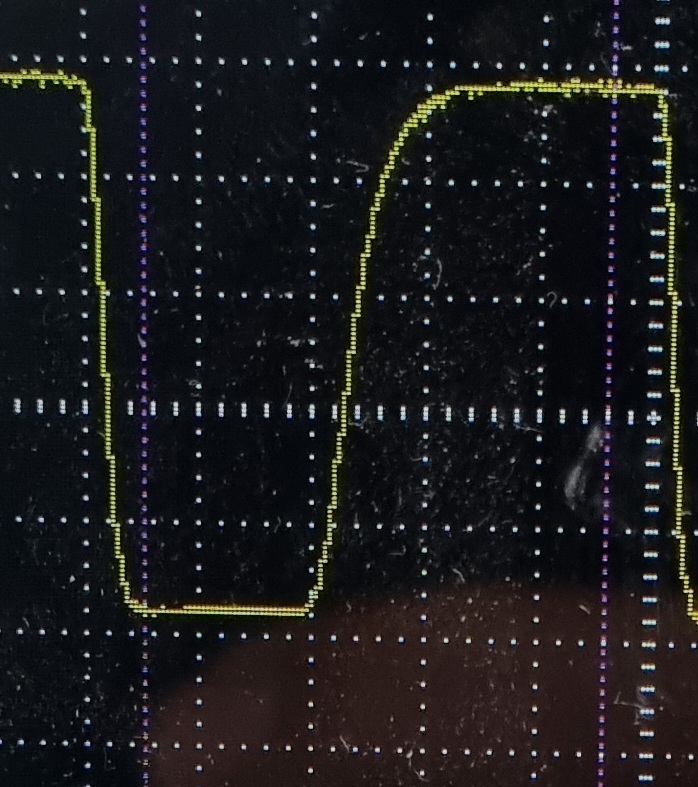
>picrel
is the LM311 out in that arrangement sinking 20mA, 1V and 200nS per div. Might be the breadboard youre seeing mostly. And slow asf 311