← Home ← Back to /diy/

Thread 2938248

12 posts 8 images /diy/
Anonymous No.2938248 >>2938283 >>2938287 >>2938306 >>2938325 >>2938361 >>2938398 >>2939029 >>2939414 >>2939427
Metal sheet planes
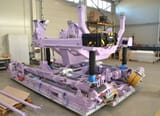
How did they designed sheets?? How did they calculated where holes should be to be sinchronized? How or what CAD they use to desing them sheets (computer days)?
Did they just make skeleton and put sheets and cuted excess out then just drilled? Like paper models? Or what? Really dont know.
Anonymous No.2938255
That's probably how they used to produce them during development before CAD, getting sheets that were more or less what the draft showed and then snipping them down after. Designer might spec one thing but the fabricator is going to make his own job easy where he can
Anonymous No.2938283
>>2938248 (OP)
Scrap paper and glue
Anonymous No.2938287 >>2938341
>>2938248 (OP)
You know how math works, right? So yeah, math. Duh.
Anonymous No.2938306
>>2938248 (OP)
Anonymous No.2938325
>>2938248 (OP)
They are designed by people who are not mentally retarded like you.
Anonymous No.2938341
>>2938287
I havea strange practical feeling that when i cut sheets the holes wouldnt fit...
Anonymous No.2938361
>>2938248 (OP)
NURBS. Its a kind of mathematical function. You design your entire body on paper based on your restrictions of material, time, money etc. (i.e. cant have infinitely thin bent edges despite it being ideal for aerodynamics, persons and machines need to fit...), then decompose this body into several subsection of 2d-nurbs.
usually it will be apporximated, esp. if you live in an age before powerful computers.

If your workshop can reliably work with 400x400 sheets, you decompose using this metric.

Actual forming is probably done using freeform cold forging.

Alternatively you copy and slightly modify what everyone else is doing.
Sieg No.2938398
>>2938248 (OP)
In fusion 360 right click convert extrusion to sheet metal, click on the line you want to be a bend, type flange distance hit enter


Under assembly mate the hole of your goal piece and your project then click create sketch extrude the thickened of your sheet and you have perfect sheet metal forms

Real world manufacturability of your designs is entirely dependent on your skill in DFM

Because cad will design and export impossible shapes to create in the real world


Just because you can draw it doesn’t make it possible to make or make cost effectively
Anonymous No.2939029
>>2938248 (OP)
Salty milk and coins
Anonymous No.2939414
>>2938248 (OP)
There are a million things that go into designing a plane. I know a guy who was on the design team for the 747 who said they needed to create a machine that makes rivets faster than the machines they had or else it wouldn't be cost effective.
Anonymous No.2939427
>>2938248 (OP)
>Did they just make skeleton and put sheets and cuted excess out then just drilled?
Basically, yeah.
Back in the old days, yes, they would first build small wooden model for aerodynamic tests, then full-sized wooden mockup, then used it as a shoemaking last to make stencils.
Then they would build a couple of non-flying prototypes using their stencils to see if it all fits, make adjustments, build proper toolings to bend metal exactly right and hold it in place so that workers could rivet it together.
Only then they could get to work on the actual prototype and finalize the design.

Now you can use 3D models and skip right to toolings.

The most complicated part of industrial design isn't making the product or designing the product.
It's designing the machines, molds and and tooling that allows you to make the product reliably and repeatedly.

This is also why you can't restart production of ancient designs that scrapped their toolings.
Most WWII plane replicas are just shells made of fiberglass fitted with modern engines because nobody has funds for a authentic production restart.